

Page 1

27/10/2011
Paxton Access
Ins-30105 - SONY number plate reader
Technical Support
01273 811011 support@paxton.co.uk
Technical help is available: Monday - Friday from 07:00 - 19:00 (GMT)
Saturday from 09:00 - 13:00 (GMT)
Documentation on all Paxton products can be found on our website - http://www.paxton.co.uk/
Site suitability checklist
All points on the following checklist must be completed to achieve a reliable installation.
The vehicle will be stationary when the number plate is read.
The camera is sited 4 to 16 metres from where the vehicle will wait at the barrier.
(Capture point)
The vertical camera angle does not exceed 25° or the lateral angle 20°.
(see Viewing angle restrictions)
The lane width is not greater than 3.5 metres.
An IR reective barrier or marker is positioned at the capture point to allow the camera
to maintain a good contrast level during periods of inactivity.
The barrier has no printed text upon it.
Only the front number plate is to be read.
No square number plates are required to be read.
Vehicle headlights are not directly pointing into the lens.
There is a clear view of the number plate without any temporary or permanent obstacles.
(e.g. passing or parked vehicles)
The sun is not directly behind the subject and reections from the number plate
will not dazzle the camera.
The SONY number plate reader uses an infrared camera to read the vehicle number plate, process the
information and then pass the details to the Net2 control unit via Wiegand output to the reader port.
The camera has manual iris, zoom and focus. It uses software to adjust the shutter speed to maintain
the maximum contrast on the number plate image.
Enter the user's number plate details into their Net2 user record. When the vehicle plate has been read
by the camera, access is then granted as appropriate and the access event is logged by Net2.
Page 1
Page 2

INSTALLATION - Mounting brackets and hardware
The supplied housing is a Videotec HOV. Detailed drawings are available on the back page.
HOV details: http://www.videotec.com/en/page_114.html
Brackets: http://www.videotec.com/en/page_267.html
Two mounting points are provided.
- Lateral - 2 x M5 bolts at 70 mm spacing
- Rectangular (with cable exit) - 4 x M5 bolts. 40 mm x 62 mm.
WARNING: The lid section of the case is much heavier than the base. Take care when carrying
or mounting the unit with the lid open that the unit is fully supported or it could overbalance !!
115/230V AC power connection
Connect the AC mains
supply with Earth wire to
the terminal block
WARNING: There is no mains power
switch on the unit. Ensure that the mains
supply is turned off before working on
any part of the power supply of this unit.
Low voltage (12V DC) connection
If required, the camera system (without the condensation heater)
may be directly powered from a 1A / 12V DC feed.
Unplug the connection to the Heater. Remove the two screws
holding the connection board and the two screws holding the
power supply module. Lift these assemblies clear of the housing.
The Brown (0v) and White (12V) connections can then be
removed from the power supply terminal block.
Connect the 12V DC feed to these wires.
Ensure that the polarity is correct before powering up the unit. Incorrect wiring
may cause irreversible damage to the 12V / 5V regulator circuit.
Connection to a Net2 ACU reader port
The data connection to the Net2 ACU only requires
the following signals.
DATA 0 Net2 - Yellow
DATA 1 Net2 - Blue
GND/0V Net2 - Black
Depress the white button on the connection block to
open the terminal and release it to grip the wire.
Connect the data cable to the Net2 ACU reader port.
Page 2
Page 3

TCP/IP connections
Power LED
Status LED
LAN connection
The CPU Monitor, Reset, Mode
and USB connection are NOT
camera outputs. They are for
Network connect LED Network data LED
software upgrades only.
Connecting to the PC
Connect your laptop PC via the supplied crossover cable to the camera. Power up the camera and the
Power (Green) and Status (Red) LED's will come on. After about 5 seconds the Status LED will go out.
Power up the PC and the Network connect LED (Green) should come on.
1. Run the web browser on the PC. This should be
Internet Explorer 5.0 or later with Windows XP or Vista.
2. Change your PC address into the: 192.168.0.x. range,
as the camera will not respond until the IP address of
the PC is brought into that range.
(See 'Changing the address on the PC' or contact Tech Support if required)
3. Connect to the following address: http://192.168.0.1
4. The cameras Network LED should now be active.
Once connected, the log-on screen should now display.
Enter the following - User name: net2
Password: net2
The main program window should then open.
Page 3
Page 4
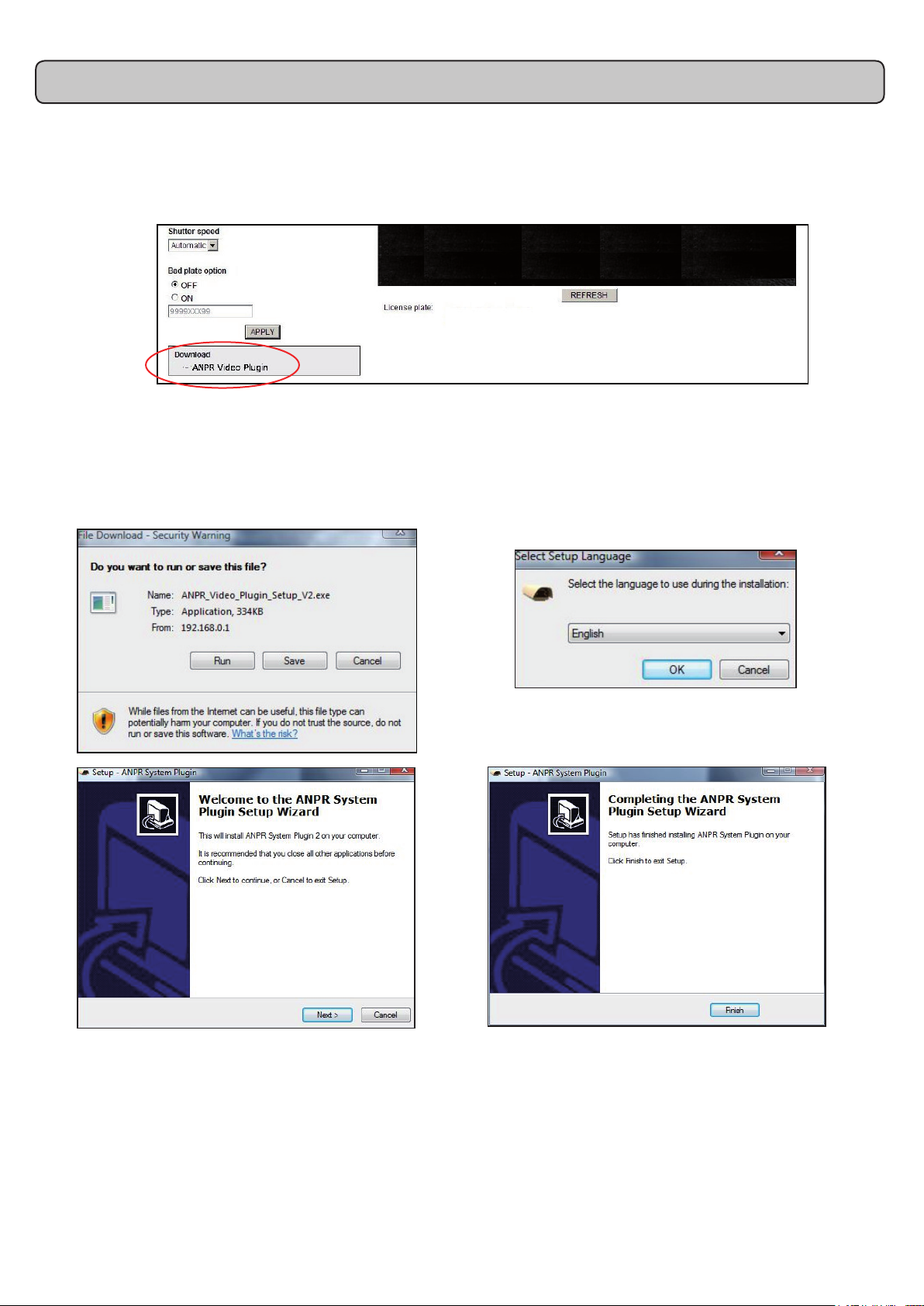
Loading the ANPR Video plugin
The rst time that the PC is used to view the video data, the ANPR video plug-in must be downloaded
to the PC from the camera.
This is done via the link displayed to the left of the main display as shown below. Click on the link:
The following screens will display while loading this plug-in.
Page 4
Page 5

Camera adjustment
The camera should be adjusted to achieve a green quality ag. The percentage score is based on the
amount of software processing that the image required to achieve the license plate displayed. Red or
amber warning ags will display if the data is considered unreliable. (See also: Image Verication)
While adjusting the camera, set 'multiple read' to ON.
1. Shutter speed - Under outdoor conditions, the shutter speed should be set to AUTOMATIC. If installed
indoors under a constant level of articial light, a xed shutter speed should be selected.
Start at 1/500 and check the contrast level seen on the plate. Adjust this setting up and down,
waiting 30 seconds each time while the camera recongures, to achieve the maximum contrast level.
2. Iris - Position a vehicle at the 'capture
point'. Start with the iris fully closed
(C = Closed) and slowly rotate the ring
until the number plate comes into view.
This should be further adjusted later to
achieve the maximum plate contrast.
3. Zoom - Adjust the Zoom until the number
plate is one third of the screen width.
4. Focus - Adjust to achieve the sharpest
image at the required distance.
5. Calibrate - Position a vehicle at the 'capture
point'. Power the camera off and on again.
Leave the vehicle in position for 3 minutes
to allow the camera to fully calibrate.
There is a delay with the viewer so do not make large or quick adjustments while focusing the camera.
Each adjustment ring can be locked in position by means of the nger screws.
Page 5
Page 6

Viewing angle restrictions
F
Calculated distances at the 20° maximum
20° maximum
lateral angle
25° maximum
vertical angle
F
Framing the camera image
O
H
Focus Distance (F)
4 m 1.5 m
10 m 3 m
15 m 5 m
Maximum offset from the
number plate centre (O)
The sum of the height and lateral angles
when combined must not exceed 40°.
Calculated distances at the 25° maximum
Focus Distance (F)
4 m 2.5 m
10 m 4 m
15 m 6 m
Maximum height above the
number plate centre (H)
1/3
1/3
1/3
Set the zoom and focus so that a sharp image of the plate lls about one third of the screen width.
You should also consider if high or wide vehicles may block the view of a close following second vehicle.
To maximise reliability:-
1. The vehicle must be stationary at the capture point.
2. The barrier has vertical IR reective banding with no additional lettering or logo.
3. The barrier or IR marker and the number plate are both in focus within the cameras eld of view.
4. The camera location conforms to the height and lateral angle limitations.
5. The barrier image is in the top part of the screen. This stops the plate being obscured if the
vehicle should stop short of the barrier.
6. The barrier forms no more than one sixth of the total image height.
7. The vehicle should move out of the eld of view within 10 seconds of the data capture to
re-establish the background reference data for the system.
Page 6
Page 7

Conguring - Net2 software (v4.13 or later)
Run the Net2 software and select the ACU and reader port where the camera is connected.
Set the Reader operating mode to 'ANPR - 26 bit Wiegand Reader'. The 'Token data format' will
then also display ANPR - 26 bit Wiegand automatically.
The user record requires the number plate details to be added. Select the user, click on 'New
token' and select 'Vehicle number plate'. Enter the details (no spaces necessary) and click OK.
Click Apply on the record to accept the new token.
Page 7
Page 8

Additional Settings - Country conguration
Select the most likely country of origin for the number plates to be
read. This does not stop the system from reading number plates
from other countries but will improve the speed and reliability of the
system if it can start with a template to work with.
For example, if countries do not use Q or I, these can be given a
low probability factor.
Select the ones required from the list or select 'Map Mode' to view
their geographical positions. Toggle the country on/off with a mouse
click and click Apply.
Keep these active selections to a minimum.
List of supported Countries
United Kingdom France Germany Ireland Spain
Belgium Croatia Denmark Luxembourg Netherland
Switzerland Italy Portugal
Under Development - Please contact Technical Support for details
Czech Republic Russia Sweden Latvia Bulgaria
Estonia Finland Greece Hungary South Africa
Lithuania Poland Romania Slovakia Norway
Canada Ukraine U S A
Network tab
- LAN
The LAN IP address used by the camera may be changed after the initial connection. It may be
benecial to x the camera IP address in the same range as the installers laptop for future use.
- SNMP (Simple Network Management Protocol)
The interface is compatible with management systems requiring this protocol.
- NTP (Network Time Protocol)
The camera is compatible with this protocol used for synchronizing the clocks of data capture systems.
Page 8
Page 9

Advanced tab
- Car Direction.
This should be set to FRONT if vehicles Enter and Exit through the same barrier preventing the
reading of number plates moving away from the camera.
- Relay Contacts (1 & 2)
These voltage free relay contacts can be congured to pulse every time a number plate is read.
They can be used to trigger other devices, for example: lighting, CCTV, alarm bell.
- Time Schedule
The camera system can be congured so that it is only active at certain times of the day/week.
- Select a rmware to upload.
These upload and reboot functions should only be used with the co-operation of Technical Support.
Number plate data
A .jpg image of the number plate and a text string are both available via the ethernet interface.
An SDK (software development kit) is available on request from Technical Support.
Bad plate option
The bad plate option can be found under the 'General' tab. This option will create a default number
should a plate be detected but due to its condition (dirty, damaged, non-standard, etc.) the reliability
score does not reach the minimum required.
The default output for this is 9999XXX99, but this can be changed. This value is sent to the Net2
which treats it like a normal token number.
Net2 will create an event as normal but can be set to allow or deny access by setting up a user record
containing this value. Using Net2 'triggers and actions' it can also sound a local alarm or send a text
or email to security if required.
Multiple read and lter
Off - The system outputs data as soon as it has made a decision on the plate number and will not
send any more data while the same plate remains in view.
On - It will continually recheck the plate number and send the data after every new decision
(up to 3 times per second) for as long as the plate remains in view.
On + Filter - As above, but only sends data if the plate number decision changes.
Page 9
Page 10

Changing the IP address on your PC
Some rewall/virus protection software and other wireless hardware can block the IP detection
process. Disable these and try to detect the camera again. Please contact Technical Support if you
require further advice.
Image verication
For each image captured and evaluated, the system gives a score as to how much processing the
image took to produce a result.
The log is directly accessed using direct PC commands via the LAN port connection.
With XP click: Start / Run / cmd
With Vista click: Start / Accessories / Command prompt
(VISTA - Telnet may need to be enabled - If help is required, please contact Technical Support)
This produces the following prompt screen. Enter the following: Telnet 192.168.0.1 8050
The log screen shows the results of any number plate analysis as it takes place. This screen will
therefore only update when a number plate is in view of the camera system.
The screen shows: Number Plate after processing, Current Time (seconds), Accuracy Score.
This score is based on a maximum of 10,000 for an image that required no correction. As a guide, the
score must be above 7,000 to be passed to Net2 but a score of between 8,000 and 9,000 should be
achievable in good conditions.
Page 10
Page 11

Dimensions
Enclosure contents
A standard tting kit is supplied by the enclosure manufacturer which includes an Allen key to
secure the lid. In addition, there are cable glands, etc. should they be needed.
A Desiccant Pack is supplied in a sealed bag. This pack is a moisture absorber and should be
removed from the sealed bag and placed inside the camera enclose just before securing the lid.
Specications
Features
Image device
Frame Rate
Electronic Shutter
Infrared Lens
Infrared Light
Camera System Range
Wiegand format
Minimum Plate Illumination
Digital I/O
Ethernet Connection
Weight
Environment
Mains supply voltage
AC Power (with Heater)
DC current (Camera + LED's)
MTBF Camera electronics
MTBF IR LED's
Heater operating range
Humidity
Operating temperature
Waterproof
1/3 progressive scan IT monochrome CCD
6 fps (VGA)
1/30 sec to 1/10000 sec
C-mount manual zoom / iris / focus; 10-40 mm
850 nm
4 m to 16 m
26 bit format
1 lx (F1.4, +18db gain)
2 x dry contacts
100Base-TX / 10 Base-T (TCP/IP)
3.8 kg
115/230V AC
Max 40 W
500 mA
50,000 hrs
50,000 hrs
15°C (+/- 3°C) to 22 °C (+/- 3°C)
20% to 80% non condensing
-20°C to 50°C
IP66 - Outdoor use
This product is not suitable for retail sale. All warranties are invalid if this product is not installed by a competent person.
Page 11
 Loading...