

Page 1

17/11/2011
Red 12v dc
Brown
Orange
Green
Yellow
Blue
Mauve
Black/White
Brown
Yellow
Reader 1
Orange
Keypad 1
+12v
0v
N.C.
N.O.
Com
N.C.
N.O.
Com
Alarm Output
0v
Contact
0v
Exit
0v
Tamper
PSU
Rx
Tx
Relay 1
Relay 2
Exit
Contact
Tamper
PSU
OK
5v
12v
Red
Brown
Orange
Green
Yellow
Blue
Mauve
Black/White
Brown
Yellow
Orange
Reader 2
Keypad 2
Power
Relay 1Relay 2Inputs
Network
CAT5 cable coding
White/Green
Green
White/Orange
Orange
1 2 3
4
Screen or spare cores
from network cable
CAUTION: for 12v d.c. readers only. For
correct connection of old 5v readers, refer to
instructions.
Serial number
241821
Test ID: 012345678901
z-1440
3
24898 00000
4
Ins-30065 - RS485 protection module
Paxton
Technical Support
01273 811011 support@paxton.co.uk
Technical help is available: Monday - Friday from 07:00 - 19:00 (GMT)
Saturday from 09:00 - 13:00 (GMT)
Documentation on all Paxton products can be found on our website - http://www.paxton.co.uk/
Net2 data line protection
Under severe electrical storm conditions, the Net2 ACU's connected to the RS485 data line can be
damaged due to the very high induced voltages that can be present.
The best method of protecting the system is to make use of Fibre Optic or Wireless Networks between
outdoor locations or within large roof spaces. These then communicate with the Net2 PC over a LAN
network using a Paxton TCP/IP converter.
Where this is not practical, the tting of surge suppressors to limit the voltage passing down the data
cable to 5V DC (RS485 standard) is strongly advised.
Where to t the modules
This module is designed to suppress high voltage transients that can damage the communications
circuits of the Net2 ACU through its data line connection.
It makes use of TRANSILTM diodes that have an instantaneous response (less than 10 picoseconds) to
any overvoltage condition and will limit the voltage to a maximum to 5V DC with reference to the 0V
screen. Under extreme conditions, the diode will fail as a short circuit to 0V. The unit will then need to
be replaced before data transmission can be resumed.
Units should be placed at either end of any vulnerable cabling run to isolate the section.
Vulnerable Area
Protection Module
Protection Module
Page 2
YLNO 5TAC
YLNO 5TAC
NEERCS
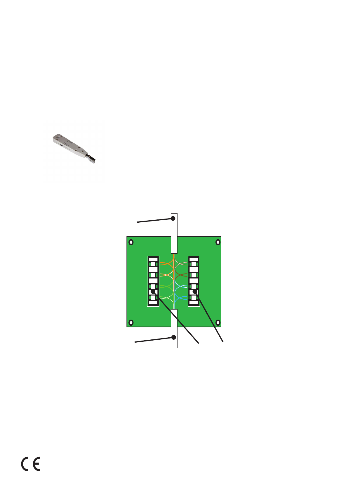
How to t the module
The unit is not dependant on the direction of the data ow. Ensure that the Green and Orange data
pairs match the correct colour positions. The Brown and Blue pair positions are grouped into a
common Screen connection.
A Krone insertion tool (not supplied) should be used to ensure a good connection of the wires into the
terminal strip.
Net2 data cable
Orange
White/Orange
Green
White/Brown
Brown
White/Blue
SCREEN
White/Green
Net2 data cable
Krone terminal strip
Blue
 Loading...