

Page 1
PROXIMITY slimline reader (697-411BL/WT)
Contents in box
PROXIMITY slimline reader
PROXIMITY slimline back plate
Fitting kit
PROXIMITY slimline reader instructions
Suitability
Products
The reader is designed to work with the Switch2 control unit (405-321) and the PC based Net2 control unit
(489-334).
PROXIMITY cards
All Paxton Access Ltd PROXIMITY tokens will work with this reader. They include the PROXIMITY card,
PROXIMITY keyfob and PROXIMITY ISO card.
Read range
The PROXIMITY slimline reader has a read range of 100mm when PROXIMITY cards are used in
conditions and 55mm when PROXIMITY keyfobs are used in normal conditions.
Environment
The reader will operate between –20
reduce the read range.
Where to use PROXIMITY slimline
o
C and +70oC. It can be mounted onto a metal frame, but this may
YES NO Reason why not
normal
Low to high use doors Behind Metal RF will not penetrate
Inside and outside Very near to TV or Monitor RF will interfere with reader
No need to shelter from the elements
Narrow door frames and inside walls
Architecturally sensitive installations
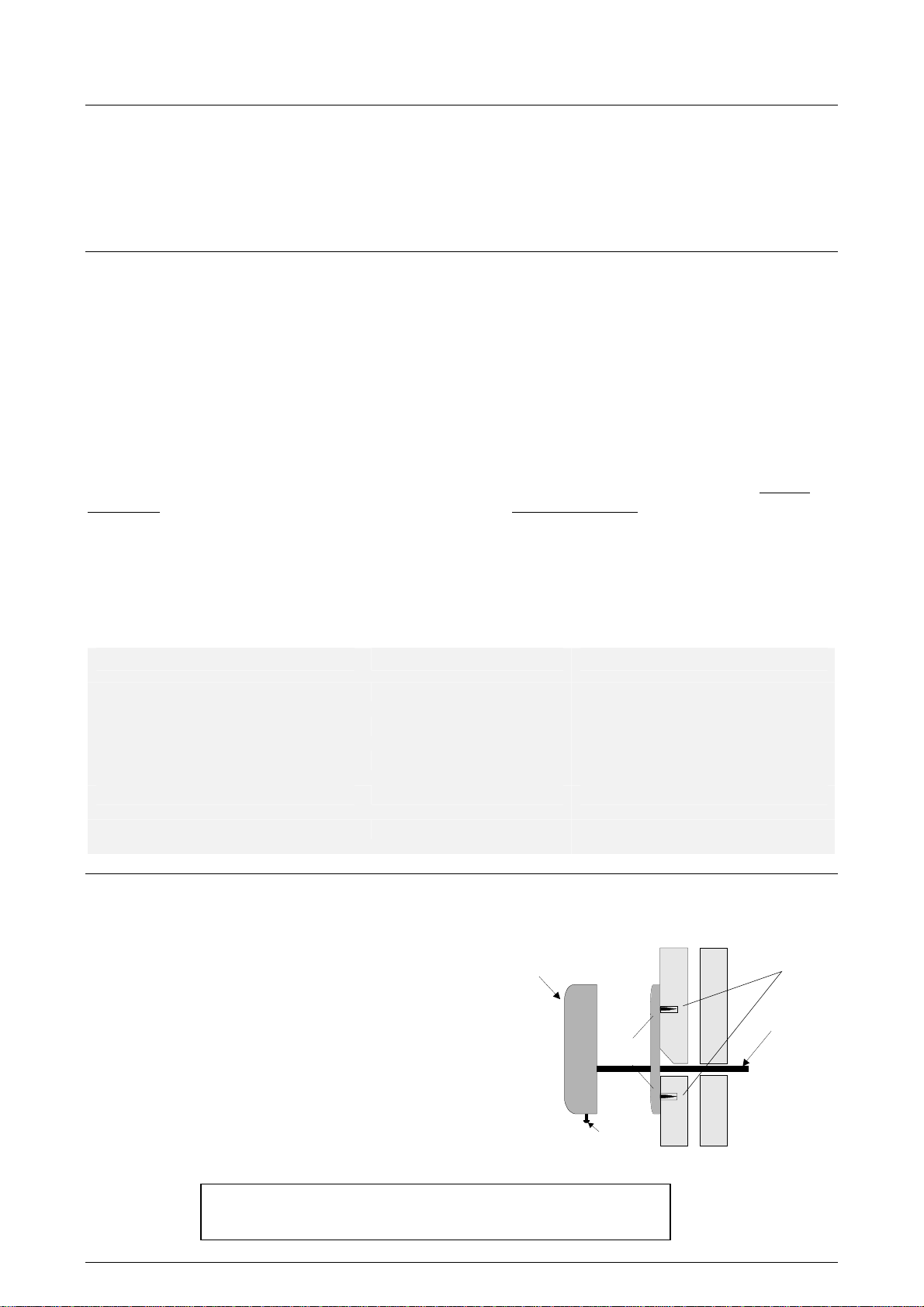
Fitting
1. Using the base plate as a template, mark
and drill holes for the cable and the four
screws.
2. Tap the four small raw plugs into the wall.
Fix the base plate securely with the screws
provided.
3. Feed the reader cable through the back
plate and hang the reader at an angle over
the back plate. Then slot the reader into
the groove at the top of the base plate and
press the reader into place.
4. Screw in the securing screw at the base of
the reader.
IMPORTANT NOTE: When fitting 2 readers for read in and
read out, the PROXIMITY readers MUST be more than 1ft apart!
PROXIMITY
slimline reader
6 x 3/4
securing screw
Wall plugs
Cable
INS-137 Date code: 180101
Page 2
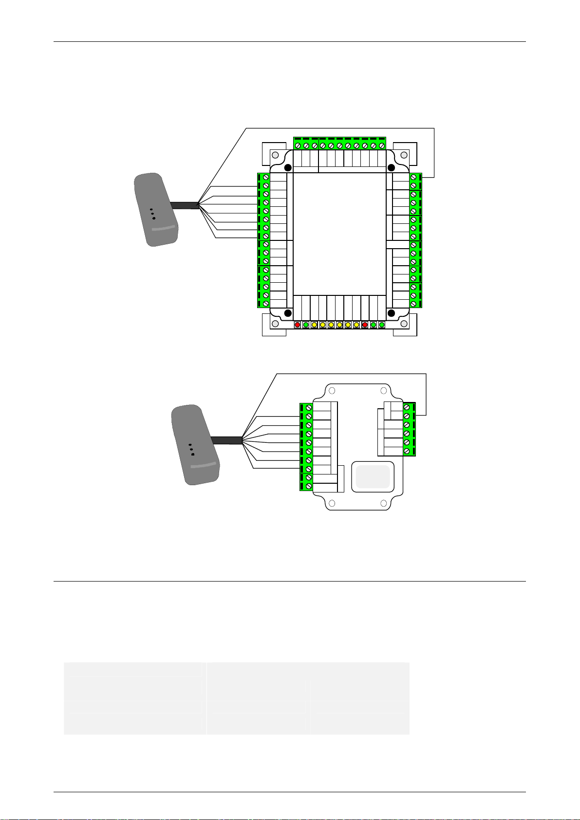
Wiring
NOTES
The reader will be sent out with an RJ45 connector on it. This can be cut off and the cable can be stripped
back ready for wiring.
PROXIMITY
slimline reader
PROXIMITY
slimline reader
** IMPORTANT **
Please note that the red wire should be connected to 12V only. This supersedes the information in the
trade brochure.
Brown
Orange
Green
Yellow
Blue
Mauve
Black
Red 12Vdc
Red
Brown
Orange
Green
Yellow
Blue
Mauve
Blk/Wht
Brown
Yellow
Orange
Screen
OUT-B
OUT-A
IN-A
IN-B
Red 12Vdc
Brown
Orange
Green
Yellow
Blue
Mauve
Black
Brown
Yellow
Orange
Reader 1 Keypad 1
Mauve
Blk/Wht
Net2
1 Door
Access Control Unit
Network
Door relay
Relay 2
Rx
Exit
Tx
Red
Brown
Orange
Green
Yellow
Blue
Mauve
Black
Contact
Exit
Blue
Contact
Card reader or keypad
Inputs
Green
Yellow
Tamper
PSU
S
witch
Control
unit
Brown
Orange
Reader 2 Keypad 2
OK
5V
2
Attach
Q.C. Label
here
Red
12V
PowerDoor relay
+12V
Power
N.C.
N.O.
Com
Door relay 1
N.C.
N.O.
Relay 2Inputs
Com
Gen O/P
Contact
Tamper
PSU
Bell
Alarm
12v
0v
N.C.
N.O.
Com
0V
0 V
0 V
Exit
0 V
Cable extensions
The reader comes with 3 Meters of non-screened cable. The type of cable used to extend this distance will
effect the maximum distance the reader can be extended. All distances are assuming that the reader is wired
according to our instructions.
ACU used
Net2 ACU 100M 100M
Switch2 ACU 100M 100M
Be sure, when extending the cable distance beyond 3M, to keep the colours the same throughout the run.
INS-137 Date code: 180101
Maximum distance from ACU
CR9538 CR9540
 Loading...