

Page 1

25/01/2010
Ins-30045 PROXIMITY marine reader
Technical Support
01273 811011
Technical help is available: Monday - Friday from 07:00 - 19:00 (GMT)
Saturday from 09:00 - 13:00 (GMT)
Documentation on all Paxton products can be found on our website - http://www.paxton.co.uk/
Fitting
Paxton
support@paxton.co.uk
Fix the backplate to the wall with the stainless steel screws provided in the tting kit. The small slot in the plate
edge should be positioned at the bottom.
Where the unit is to be tted to a smooth surface, bulkhead, etc. a gasket is supplied to provide a weatherproof
seal between the backplate and the mounting surface. (The unit has its own integral seal)
Locate the unit in the keyhole slots provided in the backplate. Make sure that the locking pin is close to the slot in
the edge of the backplate. Rotate the unit clockwise until the locking pin engages in the slot.
To remove the unit, insert a small screwdriver into the cut out provided and use it to lift the locking pin.
The unit can then be rotated anticlockwise to release it from the backplate.
Page 2
Suitability
Security-sensitive doors
Mounted on metal surface
Wiring
LED indications
The marine reader has NO Amber LED indication.
Wet environments
Readers mounted together
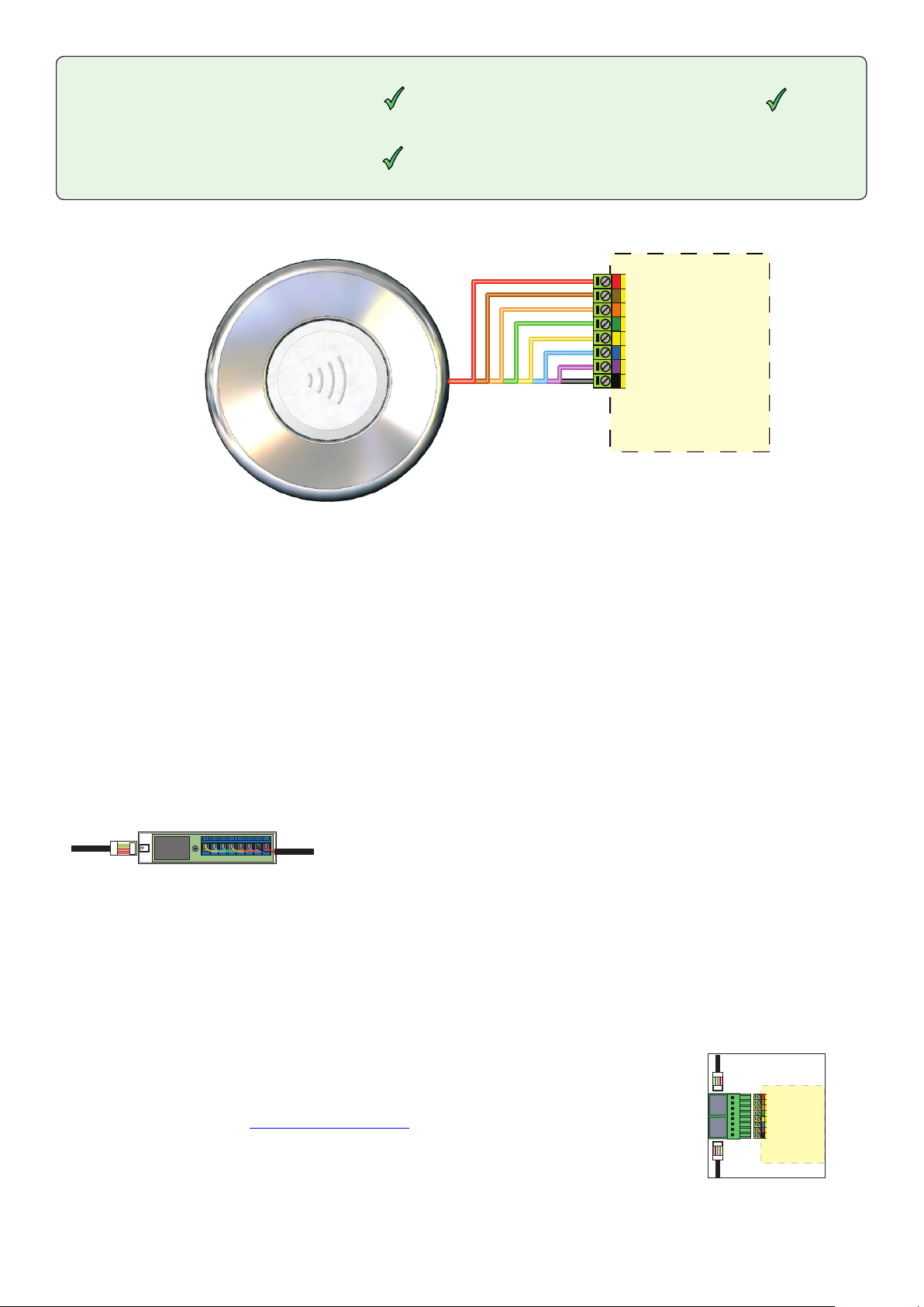
Connection to a control unit
reader port
IMPORTANT: This reader cannot be connected
in parallel with other readers and keypads.
300mm
between
readers
Blue - Normal mode (waiting for card)
Green ashing - Access Permitted
Red ashing - Access Denied
Card + PIN - Not supported
Switch 2 - Colour zoning. With only a single colour indication available, active/barred colour zones
cannot be displayed. The reader retains the display selected by the previous user card. Presenting a
valid card leaves the reader green, presenting a card for a disabled colour zone leaves the reader red.
Connection modules
Reader junction box (325-020)
This module can be used to provide a
connection point for the reader RJ45 plug.
The terminals on the module are then wired
colour for colour to the controller.
Alternatively, the reader can be wired directly
into the screw terminals of the control unit by
rst cutting off the RJ45 plug and stripping
back the wires in the cable.
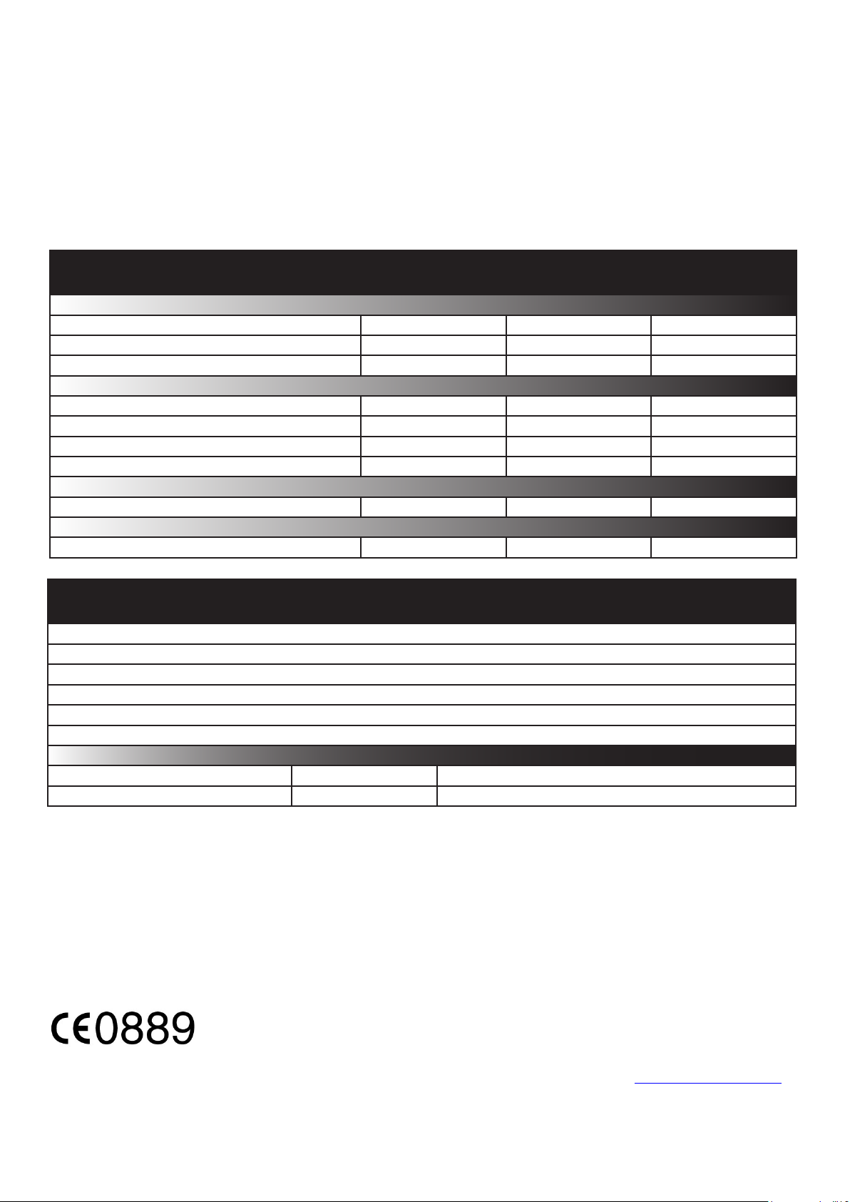
Reader port module (325-030)
This module may be purchased separately to speed up
the installation and replacement of readers.
The reader port module is designed to convert the
standard reader ports on Switch2 and Net2 controllers
to accept one or two RJ45 connections. Pull off the
screw terminal block from the reader port and simply
replace it with this module.
Further information on how to purchase Installer Tools is available at:
http://paxton.info/841
Cable extensions
Readers can be extended using Belden CR9540 10-core overall screened cable to a maximum of 100 metres.
Page 3
Backlight dimming card
The backlight on the unit may be dimmed down or turned off if required. A dimming card is provided with this unit.
Present this card within 2 minutes of powering up the reader and the backlight (blue) will reduce in brightness.
Repeated presentations will reduce the brightness in stages down to no illumination. Showing the card again will
return the backlight to full power.
Specications
Environment
Operating temperatures - all items
Waterproof
Cable length
Electrical
Voltage
Current
Carrier frequency
Clock and data bit period
Read Range
Dimensions
PROXIMITY marine reader
Reader backplate
Backplate gasket
Backlight dimming card
Documentation
Min
-35 °C
Min
8V DC 14V DC
Token Keyfob
40 mm 30 mm 400 mm
Diameter
106 mm 16 mm
Contents in box
Max
+70 °C
IPX7
Max
220 mA
Depth
Outdoor Use
5 metres
125 kHz
600 µs
Hands Free Token
Fitting kit
Kit fk1-079 3 No 8 x 1.5 in pozi pan self tapping screw - zinc
This product is not suitable for retail sale. All warranties are invalid if this product is not installed by a competent person.
Qty
3 Wall plugs
Description
The declaration of conformity is available on request. Contact details are provided at: http://paxton.info/596
 Loading...