

Page 1
Ins-30119 PROXIMITY energy saving reader
20/05/2010
Technical Support
Technical help is available: Monday - Friday from 07:00 - 19:00 (GMT)
Saturday from 09:00 - 13:00 (GMT)
01273 811011
support@paxton.co.uk
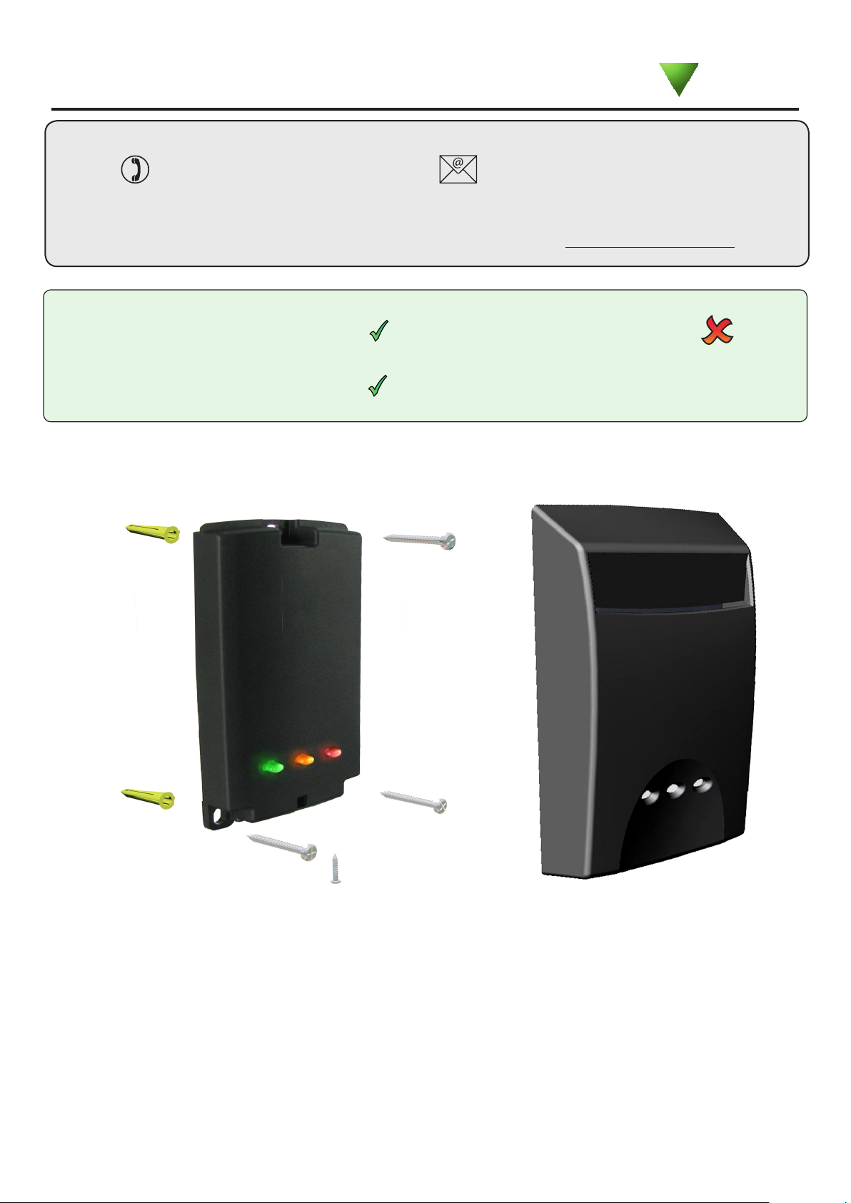
Fitting
Documentation on all Paxton products can be found on our website - http://www.paxton.co.uk/
Readers mounted together
between
readers
300 mm
Mounted on metal surface
Suitability
Controls external equipment
Wet environments
This proximity reader has a special cover that is designed to retain a user card. The presence of a card in the
reader can then be used to turn on/off other equipment when a user is present.
A reader and controller can be used to provide a voltage free relay toggled output that can either directly
switch low voltage (less than 24V DC) or, in conjunction with a mains contact relay, switch power to equipment
or lighting.
How is it used ?
Paxton
Page 2
Cable extensions
Readers can be extended using Belden CR9540 10-core overall screened cable to a maximum of 100 metres.
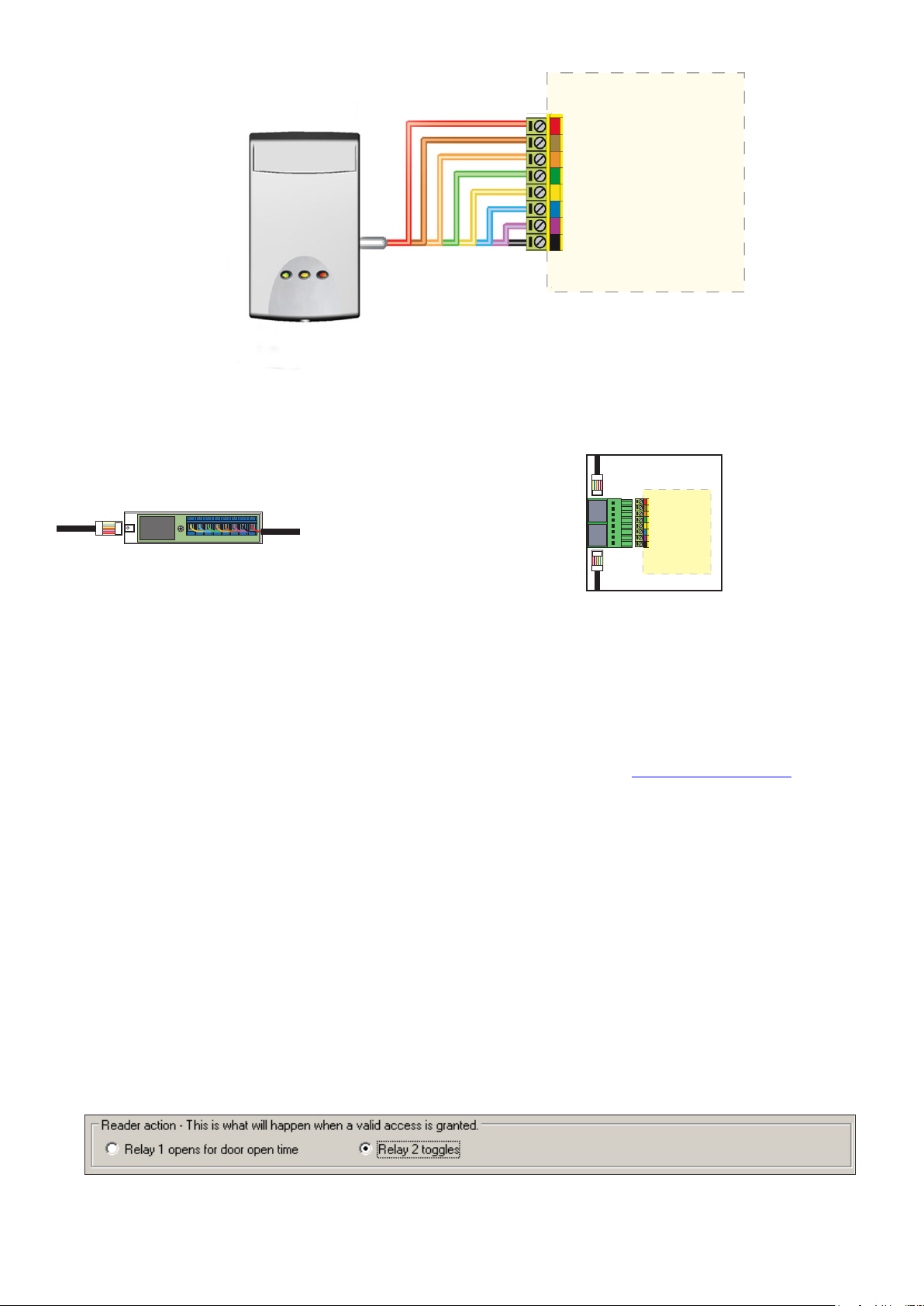
Wiring
Connection to a control
unit reader port
The reader port module is designed to convert the
standard reader ports on Switch2 and Net2 controllers
to accept one or two RJ45 connections. Pull off the
screw terminal block from the reader port and simply
replace it with this module.
This module can be used to provide a
connection point for the reader RJ45 plug.
The terminals on the module are then wired
colour for colour to the controller.
Alternatively, the reader can be wired directly
into the screw terminals of the control unit by
rst cutting off the RJ45 plug and stripping
back the wires in the cable.
Reader port module (325-030)
This module may be purchased separately to speed
up the installation and replacement of readers.
Connection modules
Further information on how to purchase Installer Tools is available at: http://paxton.info/841
Reader junction box (325-020)
When a valid user card is introduced to the reader, its card number is sent to the controller. The reader
constantly monitors for the presence of that card and once it is no longer in range of the reader (removed from
the holder) the card number is sent a second time. Paxton control units have a toggle function that will change
the state of the relay each time it receives a card number.
The system only monitors one card at a time and so a short ‘off’ period will occur if the user card in the holder
is exchanged for another.
Paxton controller relays must NOT be connected directly to the mains supply. For further
information see: AN1088 - Using the energy saving reader to switch mains power.
If the Access level of a card becomes invalid (e.g. the time period or date expires) while it is in the reader,
removing the card will NOT turn off the equipment. You will need to introduce and remove a valid card to
correct this condition.
Operation
Net2 has a toggle function assigned to Relay 2 and so either Reader port 1 or 2 can be used for this function.
You will need to select the Relay 2 toggle mode on the relevant reader screen.
Page 3

The declaration of conformity is available on request. Contact details are provided at:
http://paxton.info/596
This product is not suitable for retail sale. All warranties are invalid if this product is not installed by a competent person.
-35 °C
+66 °C
8V DC 14V DC
170 mA
125 kHz
13.56 MHz
570 µs 700 µs
61 mm 105 mm
17 mm
Compatible with the following tokens
Mifare 1K EM4100
Mifare 4K Hitag1 ISO
Mifare Ultralight / C Hitag2 ISO
Mifare Desre Paxton proximity cards
Voltage
Clock and data bit period
Carrier frequency
Specications
Operating temperatures - all items
Electrical
Environment
Dimensions
Min
Max
Width
Height
Depth
Current
Cable length
Waterproof
Min
Max
Yes - Rated IPX7
5 metres
Compatible with the following tokens
 Loading...