

Paxton Proximity 375-110, Proximity 373-110, Proximity 345-220, Proximity 371-110, Proximity 372-110 Installation Manual
...Page 1
Paxton
ins-20600
Proximity readers and Keypads
Page 2
1
2
1
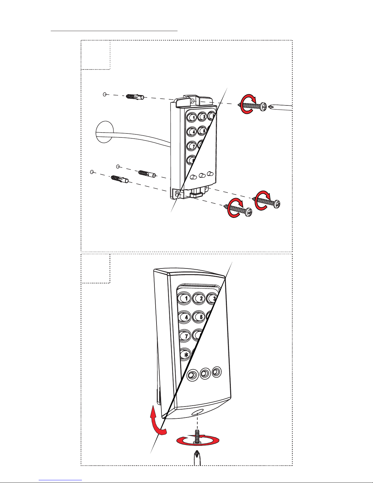
Mounting
1
Page 3
3
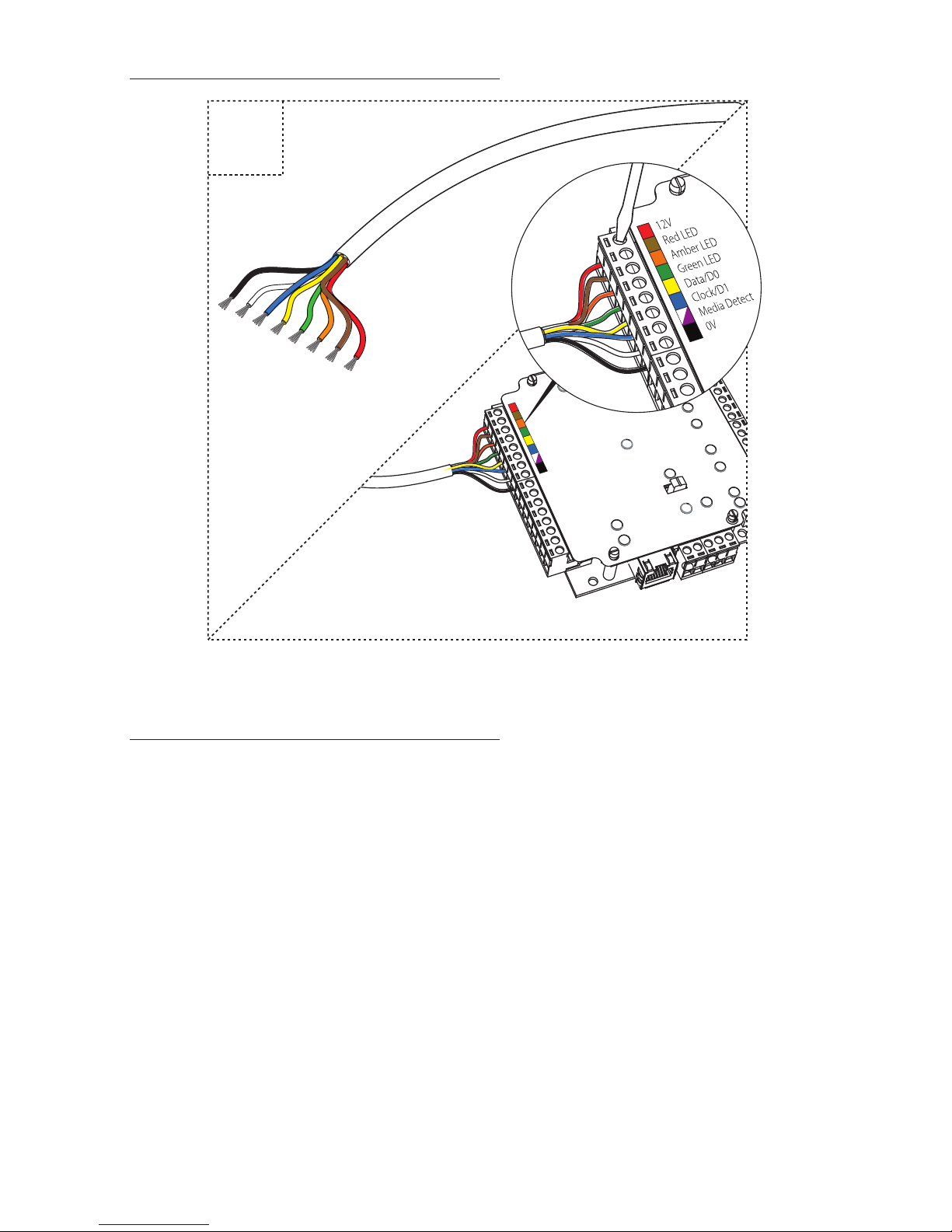
Wiring
Installation guidelines
• Readers should be mounted a minimum of 300mm/12” apart and
not back to back.
• All Proximity (P) and and keypad proximity (KP) readers should
not be mounted on metal surfaces.
• Screw connector option - The unit should be mounted in
conjunction with an electrical backbox to achieve the required
clearance for the connector. If an adaptor plate (310-750) is tted,
the mountings on the backbox can also be used.
2
Page 4
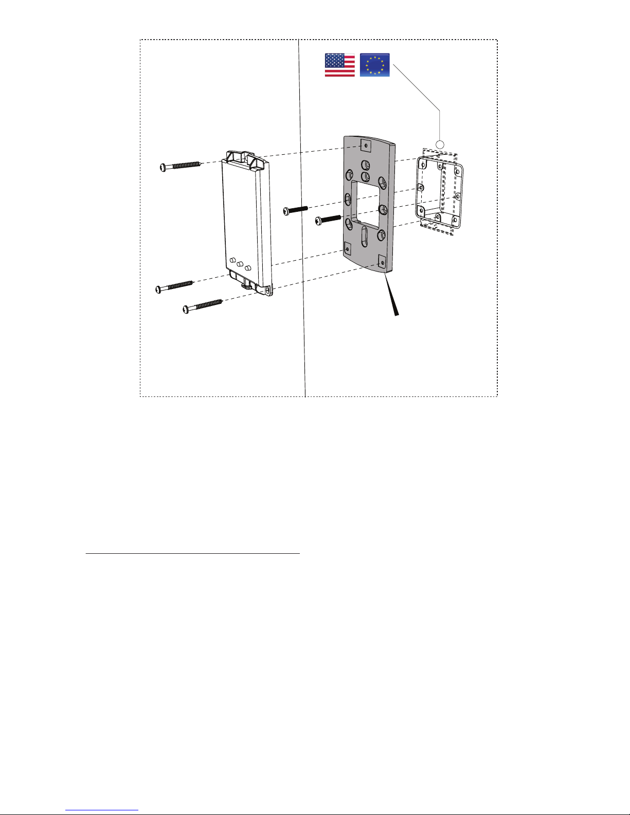
310-750-US
If a 75 series backbox adaptor kit (310-750-US) is tted, the mountings
on a backbox can also be used.
Technical Help
1 - Readers/Keypads not working.
• Software settings - Conrm that the settings of the reader or
keypad are correct.
• Connections - Check the wiring and integrity of the connectors. If
possible, test this reader on the other port.
• Extended cable - Belden 9538/9540 should be used up to a
maximum of 500 feet. Twisted pair alarm cable should not be
used. To conrm that an extended reader cable is not at fault, wire
the reader directly to the port.
• Supply voltage - Conrm that the voltage is within specication.
(see table)
3
Page 5

• User token - Conrm that the user token used for testing is OK by
presenting it to a known working reader.
• Interference - Conrm whether the reader works when tested ‘in
hand’ and not mounted on the wall.
• PROXIMITY readers should not be mounted back to back or close
to other RF devices.
2 - Readers / Keypads - Extending cable.
• Only Belden CR9538 / 9540 or a UL equivalent can be used for
cable extensions. The maximum run is 500 feet.
3 - Net2 - Using a door reader as a desktop reader.
• It is possible to congure a door reader to operate as a desktop
reader:
1 - Select the doors menu in the left hand Net2 pane.
2 - Click on the door you wish to change the reader to act as a desktop
reader.
3 - Under the relevant reader tab, change the reader operating mode to
‘Desktop Reader’.
4 - The PC displays ‘Would you like to accept desktop reader events from
this reader at the PC?’ ; click ‘Yes’
Now when you present a blank or existing token to that reader it will
allow you to add this new token or edit the existing one.
NOTE: Remember to return the operating mode to the original setting
once the cards have been read or users will not be able to gain access
through the reader. KP Reader - Ensure that Keypad type is set to ‘None’,
otherwise the Desktop reader option will not be available.
4 - Net2. What to do if a user has no access - Check the reader LED’s
when a card is shown.
• No LED’s - the reader has no power.
• No change in display - try the card on a known working reader. If
there is still no response, replace the card.
• Green LED ashing when a card is presented; check relay 1 LED to
check for activity and also the lock wiring.
• Red LED is ashing when a card is presented; check the validity of
the user at the PC.
• Check user’s access level and ensure they should have access by
clicking on Current Validity.
• Check the ‘Expires end’ date and conrm this has not been past.
• Reinstate the ACU from the doors screen. Select the ACU’s you
wish to reinstate and then click OK.
4
Page 6

375-110
373-110
371-110
372-110
345-110
345-220
130mA 130mA 130mA180mA 120mA 120mA
Current
@ 12V DC
Operating
temperature
Waterproof
HID
compatible
Handsfree
Mounted on
metal surface
-40°C - +66°C
-40°F - +151°F
Specications
http://paxton.info/1606
5
Page 7

+44 (0)1273 811011
paxton.support
support@paxton.co.uk
+1(800) 672-7298
usapaxton.support
supportUS@paxton-access.com
+49 (0) 251 2080 6900
paxton.gmbh.support
support@paxton-gmbh.de
+31 (0)76 3333 999
paxton.benelux.support
support@paxton-benelux.com
+33 (0)157 329356
support@paxtonaccess.fr
paxton.support
+44 (0)1273 811011
paxton.support
support@paxton.co.uk
+27 (0) 272 14276691
support@paxtonaccess.co.za
paxton.support
8000 3570 3783
paxton.support
support@paxtonaccess.ae
+1 (864) 751-3501
paxton.soporte
soporte@paxton-access.com
6
Page 8

The declaration of conformity is available on request. Contact details are provided at:
http://paxton.info/596
These products are not suitable for retail sale. All warranties are invalid if these products are
not installed by a competent person.
This device complies with Part 15 of the FCC Rules. Operation is subject to the following
two conditions:
(1) this device may not cause harmful interference, and (2) this device must accept any
interference received, including interference that may cause undesired operation. Changes
or modications not expressly approved by the party responsible for compliance could void
the user's authority to operate the equipment.
To comply as a UL listed installation, the following conditions must apply:-
• Server based functions (Antipassback, Time and Attendance, etc) have not been
evaluated by UL and cannot be used for UL 294 installations.
• Where an equivalent cable / wire is used it must be ‘ UL Listed ‘All interconnecting
devices must be UL Listed.
• The use of Wiegand readers and the conguration software has not been evaluated
by ‘UL’
• For CAN/ULC-S319 installations, terminals, leads and wiring methods must comply
with CSA, C22.1, Canadian electrical code, Part 1, safety standards for electrical
installations.
• The use of any add-on, expansion, memory or other module manufactured or
supplied by the manufacturer’s representative will invalidate the CAN/ULC-S319
certication.
• Wiring methods shall be in accordance with the National Electrical Code (ANSI/
NFPA70), local codes, and the authorities having jurisdiction.
Product compliance and limitations
North America:-
This device complies with Industry Canada licence-exempt RSS standard(s). Operation is
subject to the following two conditions: (1) this device may not cause interference, and (2)
this device must accept any interference, including interference that may cause undesired
operation of the device.
Classication for UL 294
FCC Compliance
1 1 4 3
Destructive attack
Line Security
encryption
Endurance Standby Power
7
Page 9

Ce dispositif est conforme à la section 15 du règlement de la FCC. Le fonctionnement est
soumis aux deux conditions suivantes : (1) ce dispositif ne doit pas créer d'interférences
nuisibles et (2) ce dispositif doit accepter toute interférence reçue, y compris des
interférences qui peuvent causer un fonctionnement non souhaité. Tout changement ou
modication non agréé par la partie responsable de la mise en conformité peut entraîner
une interdiction d'utilisation de l'équipement.
Conformité et limitations du produit
Ce dispositif est conforme au(x) standards RSS de l’industrie Canadienne sans-licence. Le
fonctionnement est soumis aux deux conditions suivantes : (1) ce dispositif ne doit pas créer
d’interférences nuisibles et (2) ce dispositif doit accepter toute interférence reçue, y compris
des interférences qui peuvent causer un fonctionnement non souhaité.
Pour que l’installation répond aux normes UL, les conditions suivantes sont applicables:-
• Les fonctions serveur (Antipassback, Pointage, etc.) n’ont pas été évalué par l’UL et ne
peuvent pas être utilisé pour les installations UL294.
• L’utilisation des lecteurs Wiegand et le logiciel de conguration n’ont pas été évalués
par ‘UL’
• Quand un cable équivalent est utilisé, il doit être ‘listé UL’Tout appareil
d’interconnexion doit être listé UL
• Pour les installation CAN/ULC-S319, les terminaux, câbles et méthodes de câblage
doivent être en accord avec CSA, C22.1, code électrique canadien, Partie 1, standards
de sécurité pour les installations électriques.
• L’utilisation de tout rajout, extension, mémoire ou module fabriqué ou fourni par le
représentant du fabricant invalidera la certication CAN/ULC-S319
• Les méthodes de câblage doivent être en accord avec le code nation électrique
(ANSI/NFPA70), codes locaux et les autorités ayant la juridiction.
Conformité FCC
• Les lecteurs doivent être installés un minimum de 300mm/12 “en dehors et pas dos
à dos.
• Tous proximité (P) et un clavier proximité (KP) lecteurs ne doit pas être monté sur
des surfaces métalliques.
• Connecteur par vis (en option) - L’appareil doit être monté avec un boitier
d’encastrement électrique pour obtenir l’espace nécessaire pour le connecteur. Si
une plaque d’adaptation (310-750-F) est xé, les xations du boitier d’encastrement
peuvent être utilisés.
Directives d’installation
8
Page 10

9
Page 11

10
Page 12

© Paxton Ltd 1.0.3
Made in the UK
01/29/2014
 Loading...