

Page 1
15/03/2011
Ins-30026 PROXIMITY P200 & P200E metal mount reader
Technical Support
01273 811011 support@paxton.co.uk
Technical help is available: Monday - Friday from 07:00 - 19:00 (GMT)
Saturday from 09:00 - 13:00 (GMT)
Documentation on all Paxton products can be found on our website - http://www.paxton.co.uk/
Suitability
Wet environments
Mounted on metal surface
Security-sensitive doors
Readers mounted together
P200
500 mm
between readers
P200E metal mount
Paxton
500 mm
between readers
Overview
The P200 is a standard P series reader with a much larger coil to give an increased read range with hands free
tokens. This larger coil makes it unsuitable for mounting the reader directly onto metal surfaces, posts, etc as
the radio eld becomes distorted and so the P200E (External) has been designed with the reader coil spaced
away from the backplate.
The read range of both units is similar to the standard P series reader with passive tokens but is greatly
extended (up to 2.5 metres) when used in conjunction with a hands free interface, tokens and keycards.
Reader covers
The P200 comes supplied with Black and White covers. The P200E is only available in Black.
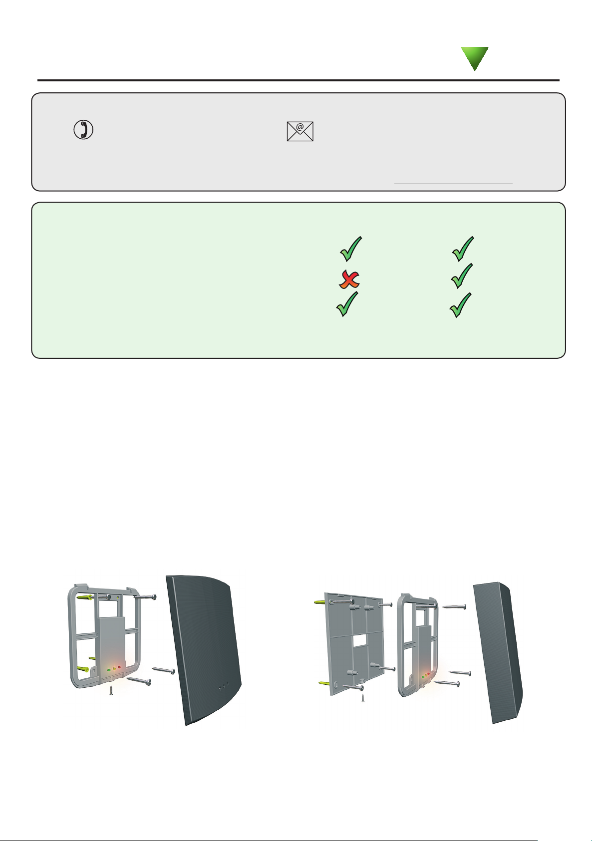
Fitting
P200
P200E
Cable extensions
Readers can be extended using Belden CR9540 10-core overall screened cable to a maximum of 100 metres.
Page 2

Wiring
Connection to a control
unit reader port
WHITE labelled control units provide 5V at the Red terminal. The Red power wire for the
reader should therefore be directly connected to the 12V supply terminal.
Hands free interface
The interface should be positioned as close as practical to the reader. A distance from interface to reader of 10
to 15 meters can be achieved but wireless technology is susceptible to environmental factors and so if problems
are experienced it may be necessary to move the interface closer to the reader.
The hands free interface should not be housed in a metal enclosure as it contains the main receiver aerial.
Sticky feet allow the interface to be stuck to the ACU wiring label in a PSU plastic housing.
Connection modules
Reader junction box (325-020)
This module can be used to provide a
connection point for the reader RJ45 plug.
The terminals on the module are then wired
colour for colour to the controller.
Alternatively, the reader can be wired directly
into the screw terminals of the control unit by
rst cutting off the RJ45 plug and stripping
back the wires in the cable.
Reader port module (325-030)
This module may be purchased separately to speed up
the installation and replacement of readers.
The reader port module is designed to convert the
standard reader ports on Switch2 and Net2 controllers
to accept one or two RJ45 connections. Pull off the
screw terminal block from the reader port and simply
replace it with this module.
Further information on how to purchase Installer Tools is available at:
http://paxton.info/841
Page 3

Technical Help
Here is the list of topics about this product that receive the most technical support enquiries.
We list them here to help you speed up the installation and trouble shooting process.
1 - Readers/Keypads not working.
Q- Software settings - Conrm that the settings of the reader or keypad are correct.
Q- Connections - Check the wiring and integrity of the connectors. If possible, test this reader on the other port.
Q- Cable - Belden 9540 should be used to extend the reader cable (100 m maximum). Twisted pair alarm cable
Q should not be used. To conrm that an extended reader cable is not faulty, wire the reader directly to the port.
Q- Supply voltage - Conrm that the voltage is within specication. (see table)
Q- User token - Conrm that the user token used for testing is OK by presenting it to a known working reader.
Q- Interference - Conrm whether the reader works when tested 'in hand' and not mounted on the wall.
Q Ensure PROXIMITY readers are not mounted back to back and there is no interference from other RF devices.
2 - Readers / Keypads - Extending cable.
QOnly Belden CR9538 / 9540 can be used for cable extensions. CR9538 8 core up to 25 m, CR9540 10 core
Qup to 100 m (maximum). With CR9540, the two additional cores should be used to double up the power.
3 - Net2. What to do if a user has no access - Check the reader LED's when a card is shown.
Q- No LED's - the reader has no power.
Q- No change in display - try the card on a known working reader. If there is still no response, replace the card.
Q- Green LED ashing when a card is presented; check relay 1 LED to check for activity and also the lock wiring.
Q- Red LED is ashing when a card is presented; check the validity of the user at the PC.
Q Check user's access level and ensure they should have access by clicking on Current Validity.
Q Check the 'Valid Until' date and conrm this has not expired.
Q- Reinstate the ACU from the doors screen. Select the ACU's you wish to reinstate and then click OK.
4 - Switch2 - Adding an additional card pack.
QYou need to be in possession of the original enrolment card. Present the original enrolment card to the reader
Qand the Amber LED will ash, Green & Red LED's will be off, then present the Enrolment card from the new
Qcard pack; the reader will beep and all LED's will be lit. The additional cards will now be valid. Repeat this with
Qeach reader and with any additional card packs. Any valid enrolment card can be used to add further packs.
QThis is the same for enrolling function card packs onto a system.
5 - Switch2 - How to reset the controller.
Q1. Disconnect the power and remove the wires from the Green and Mauve terminals.
Q2. Insert a wire link between the Green and Mauve terminals.
Q3. Reconnect the power (the unit will beep 4 times).
Q4. Disconnect the power and remove the link wire, reconnect the Green and Mauve wires.
Q5. Reconnect the power (the unit will beep 3 times per second). The unit is ready to be enrolled.
Specications
Electrical
Voltage
Current
Carrier frequency
Clock and data bit period
Environment
Operating temperatures - all items
Waterproof
Read Range
P200 80 mm 50 mm
P200E (metal mount)
Dimensions
P200 200 mm 200 mm
P200E (metal mount)
Min
10V DC 14V DC
Min
-20 °C +55 °C
IPX7
Token
80 mm 50 mm
Width
205 mm 205 mm
Max
140 mA
Max
Keyfob
Height
125 kHz
600 µs
Outdoor Use
Hands Free Token
2500 mm
2000 mm
Depth
18 mm
42 mm
The declaration of conformity is available on request. Contact details are provided at: http://paxton.info/596
Paxton Access Ltd hereby declares that this product is in conformity with all the essential requirements of Directive
1999/5/EC. This equipment is intended for use in all EU and EFTA countries and all other countries worldwide.
This product is not suitable for retail sale. All warranties are invalid if this product is not installed by a competent person.
 Loading...