

Page 1

System
System
Administrator’s
Administrator’s
Guide
Guide
04/18/07 7512
$15.50
653258
Monarch
Pathfinder Ultra
Platinum
®
®®
Printer
SALE
58523
49
32232
$25.00
PEARL EARRINGS
8
04/18/07
99565
45453
7512
9
$200.00
TC6039SA Rev. AF 4/08 ©2007 Paxar Americas, Inc. a subsidiary of Avery Dennison Corp. All rights reserved.
Page 2

This device has been tested and found to comply with the limits for a Class B digital
device pursuant to Part 15 of the Federal Communications Commissions Rules and
Regulation. These limits are designed to provide reasonable protection against harmful
interference when the equipment is operated in a commercial environment. This
equipment generates, uses, and can radiate radio frequency energy and, if not installed
and used in accordance with the instruction manual, may cause harmful interference to
radio communications. Operation of this equipment in a residential area is likely to
cause harmful interference in which case the user will be required to correct the
interference at his own expense. However, there is no guarantee that interference will
not occur in a particular installation.
If the equipment does cause harmful interference to radio or television reception, which
can be determined by turning the equipment off and on, the user is encouraged to try to
correct the interference by one or more of the following measures:
♦ Re-orient or relocate the receiving antenna.
♦ Increase the separation between the equipment and receiver.
♦ Connect the equipment into an outlet on a circuit different from that which the
receiver is connected.
This Class B digital apparatus meets the requirements of the Canadian InterferenceCausing Equipment Regulations.
Cet appareil numérique de la Classe B respecte toutes les exigences du Règlement sur
le Matériel Brouilleur du Canada.
Trademarks
Monarch®, Pathfinder®, Ultra®, Pathfinder® Ultra®, 6039, 9462, and 9465 are
trademarks of Paxar Americas, Inc.
Paxar® is a trademark of Paxar Corporation.
Avery Dennison® is a trademark of Avery Dennison Corporation.
Microsoft® and Windows® are trademarks of Microsoft Corporation.
Symbol® and Spectrum24® are trademarks of Symbol Technologies.
Motorola® is a trademark of Motorola, Inc.
Avery Dennison Printer Systems Division
170 Monarch Lane
Miamisburg, OH 45342
Outside the U.S., send batteries to:
Paxar EMEA, 4 Awberry Court
Croxley Business Park, Hatters Lane,
Watford, WD18 8PD
Page 3

TABLE OF CONTENTS
INTRODUCTION 1-1
Using This Manual .................................................................................. 1-1
Audience................................................................................................ 1-1
ADMINISTRATIVE TOOLS 2-1
Using the Taskbar Lockdown Option ......................................................... 2-1
Locking the Taskbar............................................................................. 2-1
Removing Applications ......................................................................... 2-2
Removing Applications ......................................................................... 2-3
Unlocking the Taskbar.......................................................................... 2-3
Using Asset Tracking............................................................................... 2-3
Editing Owner Data.............................................................................. 2-3
Printing an Asset Tracking Label ........................................................... 2-4
Printing an Asset Tracking Label ........................................................... 2-5
Using Printer Passthru............................................................................. 2-5
CONFIGURING WIRELESS SETTINGS 3-1
About the 802.11b Wireless Card.............................................................. 3-1
Using the Mobile Companion.................................................................... 3-1
Finding a Network................................................................................ 3-2
Creating a Profile ................................................................................3-3
Setting a Password.............................................................................. 3-4
About the 802.11b/g Wireless Card........................................................... 3-5
Using Fusion .......................................................................................... 3-5
Finding a Network................................................................................ 3-6
Creating a Profile ................................................................................3-7
Setting a Password.............................................................................. 3-9
i
Page 4

USING PRINTER DIAGNOSTICS 4-1
Accessing Printer Diagnostics .................................................................. 4-1
Testing the Print Engine .......................................................................... 4-1
Checking Machine Totals...................................................................... 4-2
Printing Diagnostic Labels .................................................................... 4-3
Checking the Stock Registration............................................................ 4-5
Testing the Sensors ............................................................................. 4-7
Testing the Printhead........................................................................... 4-9
Viewing the Print Engine Memory Expansion Directory .......................... 4-10
Testing the Keypad ............................................................................ 4-11
Testing the Speaker........................................................................... 4-11
CONFIGURING THE SCANNER 5-1
Setting Scanner Options .......................................................................... 5-1
Enabling Specific Bar Codes .................................................................... 5-5
Configuring UPC/EAN Bar Codes .......................................................... 5-5
Configuring UPC/EAN Bar Codes .......................................................... 5-6
Configuring Code 39 Bar Codes ............................................................ 5-9
Configuring Code 128 Bar Codes......................................................... 5-11
Configuring I 2of5 Bar Codes .............................................................. 5-12
Configuring MSI Bar Codes................................................................. 5-13
Configuring MSI Bar Codes................................................................. 5-13
Configuring Codabar Bar Codes .......................................................... 5-14
Configuring Code 93 Bar Codes .......................................................... 5-15
Configuring D 2of5 Bar Codes............................................................. 5-16
Configuring RSS Bar Codes................................................................ 5-17
Printable Bar Codes vs. Scannable Bar Codes ......................................... 5-18
USING SCANNER DIAGNOSTICS 6-1
Performing Scanner Diagnostics............................................................... 6-1
Setting the Scanner Mode........................................................................ 6-3
Setting the Trigger Mode ......................................................................... 6-3
SCAN STATUS VALUES A-1
ii
Page 5

INTRODUCTION
The Monarch® Pathfinder® Ultra® Platinum 6039™ printer prints,
scans bar codes, collects data, and communicates with other
devices. The printer operates on a modified Microsoft Windows CE
platform.
Information in this document supercedes information in previous versions.
Check our Web site (www.monarch.com) for the latest documentation and
release information.
Note: Before you begin, review the safety information in the Regulatory
Compliance document included with your printer.
1
Using This Manual
Following is a summary of the contents of this manual.
Chapter Contents
1 Introduction Information you should know before using the printer.
Administrative
2
Tools
Wireless
3
Configuration
Printer
4
Diagnostics
Scanner
5
Configuration
Scanner
6
Diagnostics
Using the taskbar lockdown, asset tracking, and
printer passthru options.
Setting communications between your wireless
printer and network.
Using printer diagnostics to print test labels, check
sensors, view inches printed, etc.
Configuring the scanner to accept certain bar codes
and setting the scanner and trigger modes.
Using scanner diagnostics.
Audience
This manual is for the System Administrator who configures the printer and
scanner and performs diagnostics.
A Quick Reference for this printer is available in the box.
The Programmer’s Manual and other documentation are available on our
Web site.
Introduction 1-1
Page 6

1-2 System Administrator’s Guide
Page 7
ADMINISTRATIVE TOOLS
Use these tools to
♦ lock the taskbar to restrict user access
♦ identify and track your printers
♦ send MPCLII packets directly to the printer.
2
Using the Taskbar Lockdown Option
The Taskbar Lockdown option prevents access to the Start Menu or any
unspecified applications without a password. The system administrator
selects which applications are accessible when the taskbar is locked.
Locking the Taskbar
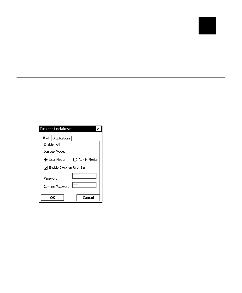
1. From the Start Menu, tap Settings, Control Panel, Taskbar Lockdown.
2. Check Enable under the Basic tab.
3. Select the Startup Mode for the user or administrator.
To disable the clock display on the taskbar, uncheck the Enable Clock
on User Bar.
4. Enter and confirm a password. The default password is 123321.
Note: Make a note of the password if you change it. You must have the
current password to unlock the taskbar.
Administrative Tools 2-1
Page 8
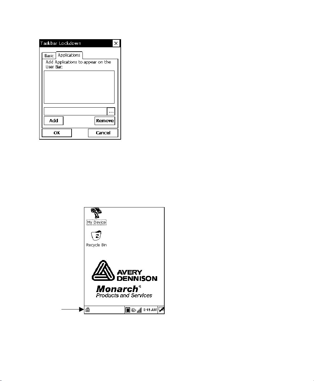
5. Tap the Applications tab.
6. Tap the browse button (…) and select an application that the user has
permission to run.
7. Tap OK. The selected application path appears in the browse field.
8. Tap Add. The application appears in the list.
9. When you are finished, tap OK, then Yes. The printer restarts.
A small lock icon appears over the Start Menu when the taskbar is locked.
Lock Icon
2-2 System Administrator’s Guide
Page 9
Removing Applications
If an application is removed from the list, the user no longer has access to
that application when the taskbar is locked.
1. From the Taskbar Lockdown screen, tap the Applications tab.
2. Select the application to remove from the list.
3. Tap Remove. The application disappears from the list.
4. When you are finished, tap OK, then Yes. The printer restarts.
Unlocking the Taskbar
To unlock the taskbar:
1. Tap the lock icon at the bottom-left of the taskbar. The Input Panel
keyboard appears on the display.
2. Enter the Administrator password and tap OK.
To re-lock the taskbar, tap the lock icon again, which has moved to the
bottom-right side of the screen.
Using Asset Tracking
Asset tracking contains the manufacturer’s product ID and serial number,
and the owner’s product ID and serial number. A password is required to
edit this data. You can print an asset tracking label that contains the product
IDs and serial numbers for your records.
Editing Owner Data
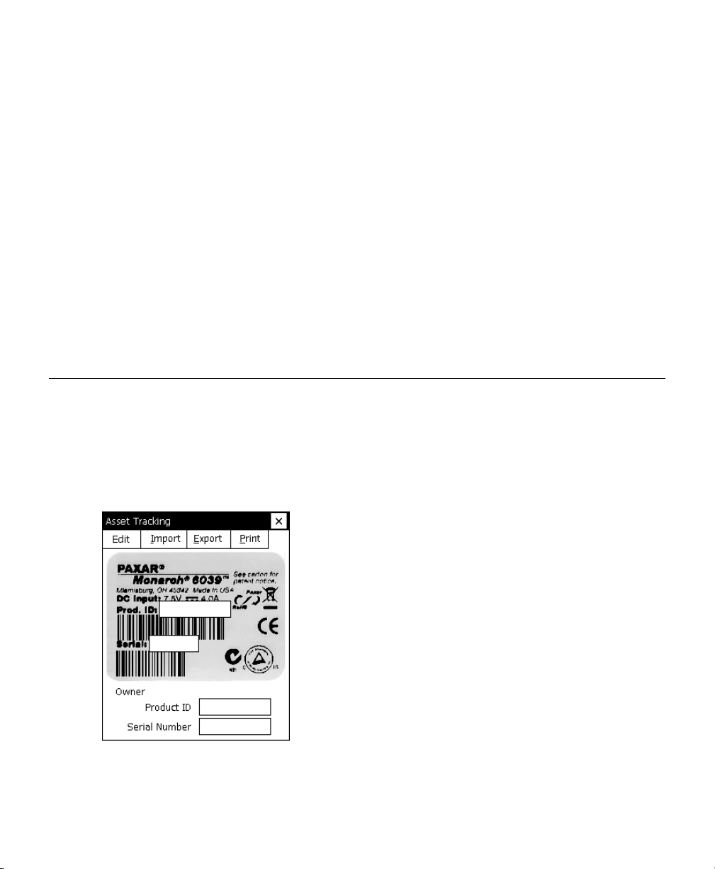
1. From the Start Menu, tap Settings, Control Panel, Asset Tracking.
2. Tap Edit. Use the keypad to enter the password and press Enter.
The default password is 123321.
Administrative Tools 2-3
Page 10

The Owner Product ID field is highlighted.
3. Use the keypad or scan a bar code to enter a new Product ID and press
Enter.
The Owner Serial Number field is highlighted.
4. Use the keypad or scan a bar code to enter a new Serial Number and
press Enter.
Note: You can only edit owner data. The Paxar Product ID and Serial
Number cannot be changed.
5. Tap Export to create a backup file of the new data on your computer or
server, then tap OK.
6. Tap Import to retrieve a backup file from your computer or server, then
tap OK. The retrieved data appears on the screen.
2-4 System Administrator’s Guide
Page 11
Printing an Asset Tracking Label
1. From the Asset Tracking screen, tap Print.
A label prints with the Paxar and Owner
Product IDs and Serial Numbers and their
corresponding bar codes.
Note: You may want to keep this label in a
safe place for future reference.
2. Tap OK, then X in the upper-right corner of
the screen to exit the application.
Asset Tracking Label
Using Printer Passthru
Printer passthru mode is an easy way to send an MPCLII packet (format,
font, batch, graphic, etc.) directly to the printer. When designing a format,
use printer passthru to send the format and batch to the printer to see how
the format looks.
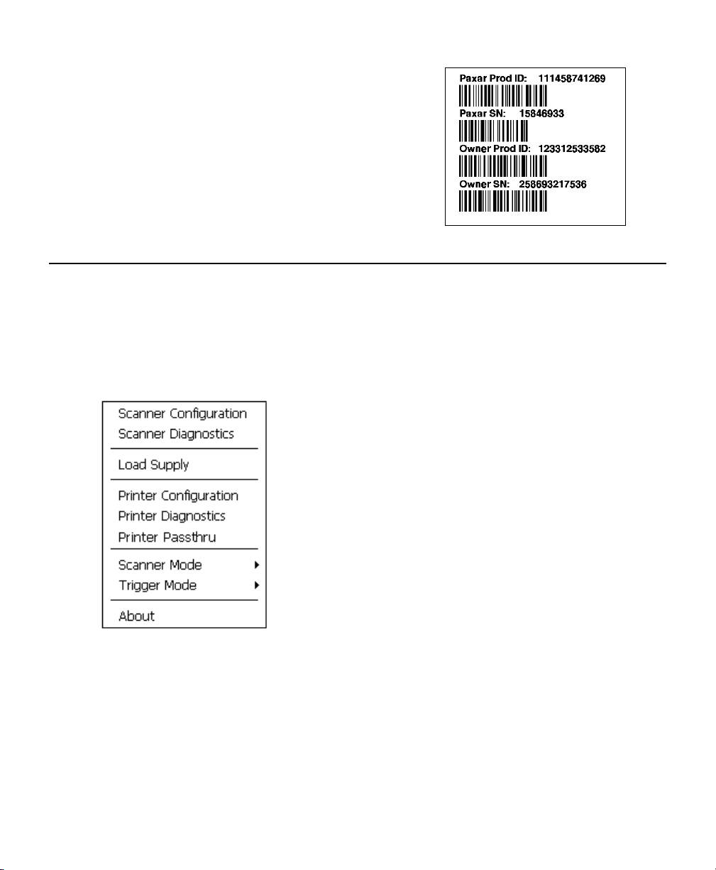
1. Tap the printer icon in the System Tray.
Administrative Tools 2-5
Page 12
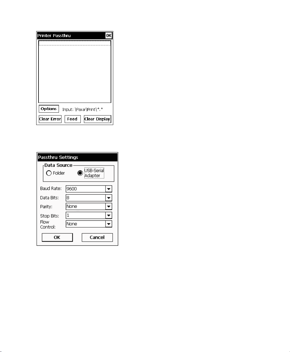
2. Tap Printer Passthru.
3. Tap Options.
4. Select Data Source as Folder or USB-Serial Adapter.
If you select Folder, the printer looks for packets in the \Paxar\Print
folder. Make sure packets are saved in the \Paxar\Print folder.
If you select USB-Serial Adapter, you must set the communication
settings and attach the USB cable via the USB-Serial adapter.
5. Tap OK.
2-6 System Administrator’s Guide
Page 13

6. Send a packet.
The text of the packet appears as well as any error messages or
status for the packet.
Tap Clear Error to clear an error on the printer.
Tap Feed to feed a blank label.
Tap Clear Display to clear the Printer Passthru screen.
Note: If your battery power level is too low, printing is disabled. Refer to
the Operator’s Handbook for more information about the battery
status.
7. When you are finished, tap OK to return to the desktop.
Administrative Tools 2-7
Page 14

2-8 System Administrator’s Guide
Page 15

CONFIGURING WIRELESS
3
SETTINGS
Use this chapter to configure the 802.11b and 802.11b/g wireless (radio)
card settings.
About the 802.11b Wireless Card
The Symbol® Spectrum24® 802.11b wireless card operates at speeds of up
to 11Mbps on any 802.11b wireless compatible network. You can use the
printer in Ad-Hoc (peer-to-peer) or AP (access point or Infrastructure)
wireless mode. Use the Windows® CE Mobile Companion utility available on
your printer to configure the wireless card to communicate with your network.
Using the Mobile Companion
The Mobile Companion utility starts automatically when you turn on the
printer and an icon appears in the System Tray.
Note: You may need to be in Admin Mode to access wireless features.
See Chapter 2, “Administrative Tools” for more information.
Tap the Mobile Companion icon
appears.
Menu Option Description
Status
WLAN Profiles Lists existing profiles to connect or edit.
Find WLANs
Options
Displays the current connection’s signal strength, IP
information, ping tests, and available access points.
Searches for available networks, signal strength, and any
encryption.
Enables or disables wireless modes (Ad-Hoc or AP)
roaming, sounds, and set/change passwords.
in the System Tray. The main menu
Configuring Wireless Settings 3-1
Page 16
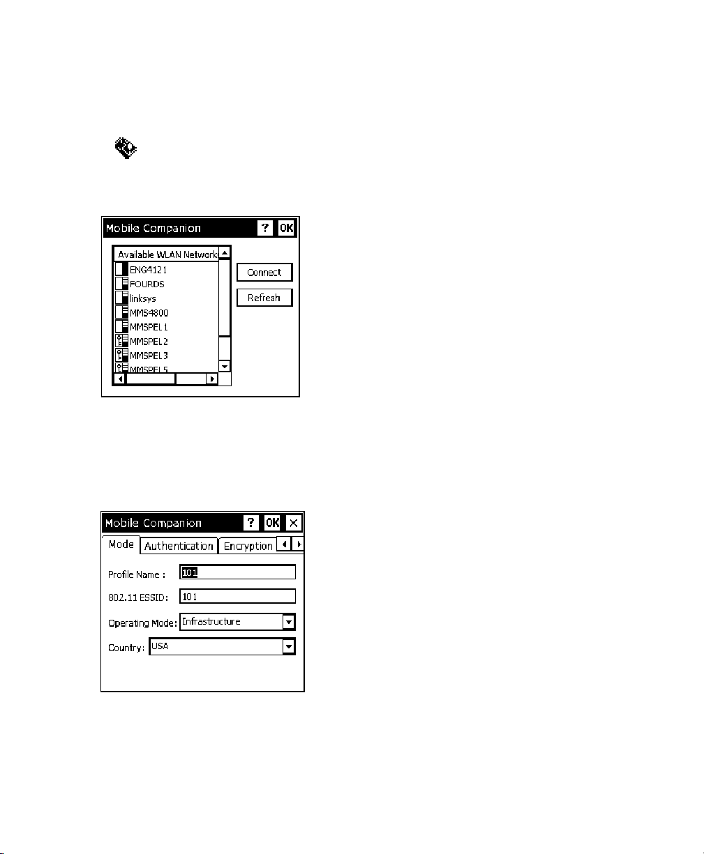
Finding a Network
The printer searches for available networks and lists the SSIDs, signal
strength, and encryption for each network. You can connect to an existing
network profile if you have the required network security information.
1. Tap
The printer searches for all networks in range and lists them
alphabetically by SSID. This may take a few minutes.
Note: A key indicates that encryption is enabled on the access point. You
2. Select a network and tap Connect.
The Profile Configuration screen appears.
, Find WLANs.
must have the network encryption settings to connect to a protected
access point.
3. Verify the mode, authentication, encryption, and IP configuration
settings.
4. Tap OK when you are finished.
3-2 System Administrator’s Guide
Page 17
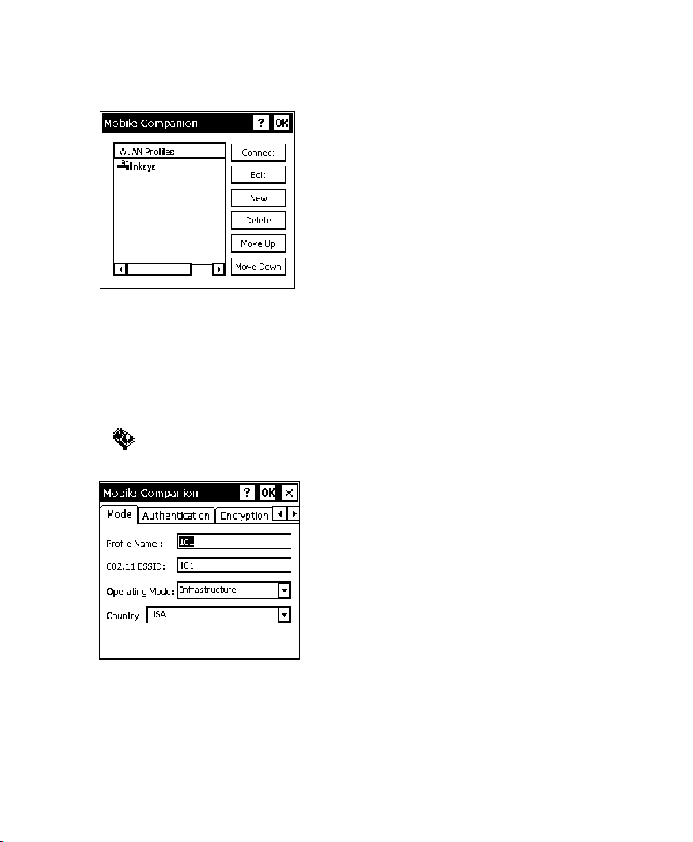
The WLAN Profiles screen appears. When you connect to a network,
Mobile Companion creates a profile for that connection.
Your selected profile is shown with an access point icon.
Note: The icon indicates a connection to this profile. To connect to a
different profile, select the profile name and tap Connect.
5. Tap OK to return to the desktop.
Creating a Profile
You can create a new connection profile if the network you need does not
appear in the list of available profiles.
1. Tap
2. Tap
, WLAN Profiles.
New. The Profile Configuration screen appears.
3. Enter a profile name and SSID to identify the printer on the network.
The default name is 101.
4. Specify the wireless operating mode. The options are Ad-Hoc or
Infrastructure.
Configuring Wireless Settings 3-3
Page 18

5. Tap the Authentication tab and specify the authentication security
settings. The options are None, Kerberos, EAP-TLS, or PEAP.
These settings must match the network authentication settings or the
printer cannot connect.
6. Tap the Encryption tab and specify the encryption settings.
The options are Open System (no security), WEP, or TKIP (WPA).
These settings must match the network encryption settings or the printer
cannot connect.
7. Tap the IP Config tab and select the IP type. The options are DHCP or
Static.
8. Tap the Power tab and adjust the radio transmission power, if
necessary.
9. When you are finished, tap OK. You return to the desktop.
10. Tap
, WLAN Profiles. The new profile is listed.
Setting a Password
You can set or change the Mobile Companion access password. The default
is Disabled.
1. Tap
2. Tap Change Password.
3. To enable password protection, enter and confirm a new password.
To change a current password, enter the current password, then
enter and confirm a new password.
To disable password protection, enter the current password but do
not specify a new password.
4. Tap OK.
5. Tap X in the upper-right hand corner of the screen to exit the application.
Note: Make a note of the password if you change it. Setting a password
, Options.
restricts all access to wireless features.
3-4 System Administrator’s Guide
Page 19

About the 802.11b/g Wireless Card
The Motorola® LA-5127 802.11b/g wireless card operates at speeds of up to
11Mbps in 802.11b mode and 54Mbps in 802.11g mode on any wirelesscompatible network. You can use the printer in Ad-Hoc (peer-to-peer) or
Infrastructure (access point) wireless mode. Use the Fusion utility available
on your printer to configure your wireless card to communicate with your
network.
Using Fusion
The Fusion utility starts automatically when you turn on the printer and an
icon appears in the System Tray.
Note: You may need to be in Admin Mode to access wireless features.
See Chapter 2, “Administrative Tools” for more information.
Tap the Fusion icon
Menu Option Description
Wireless Status
Wireless Diagnostics
Find WLANs
Manage Profiles Lists existing profiles for connecting or editing.
Options
Log On/Off
Enable/Disable Radio Turns the radio on and off.
Cancel Menu Closes the menu.
Exit
in the System Tray. The main menu appears.
Displays the current connection’s signal strength,
IP address, and version information.
Troubleshoots your connection using ping tests and
trace routes.
Searches for available networks, signal strength, and
any encryption.
Enables or disables wireless mode,
(Ad-Hoc or Infrastructure), roaming, and other system
options, import/export settings, and set/change
passwords.
If you have a password-protected profile, select this
option to enter your username and password.
Closes Fusion and removes the icon from the System
Tray.
Configuring Wireless Settings 3-5
Page 20
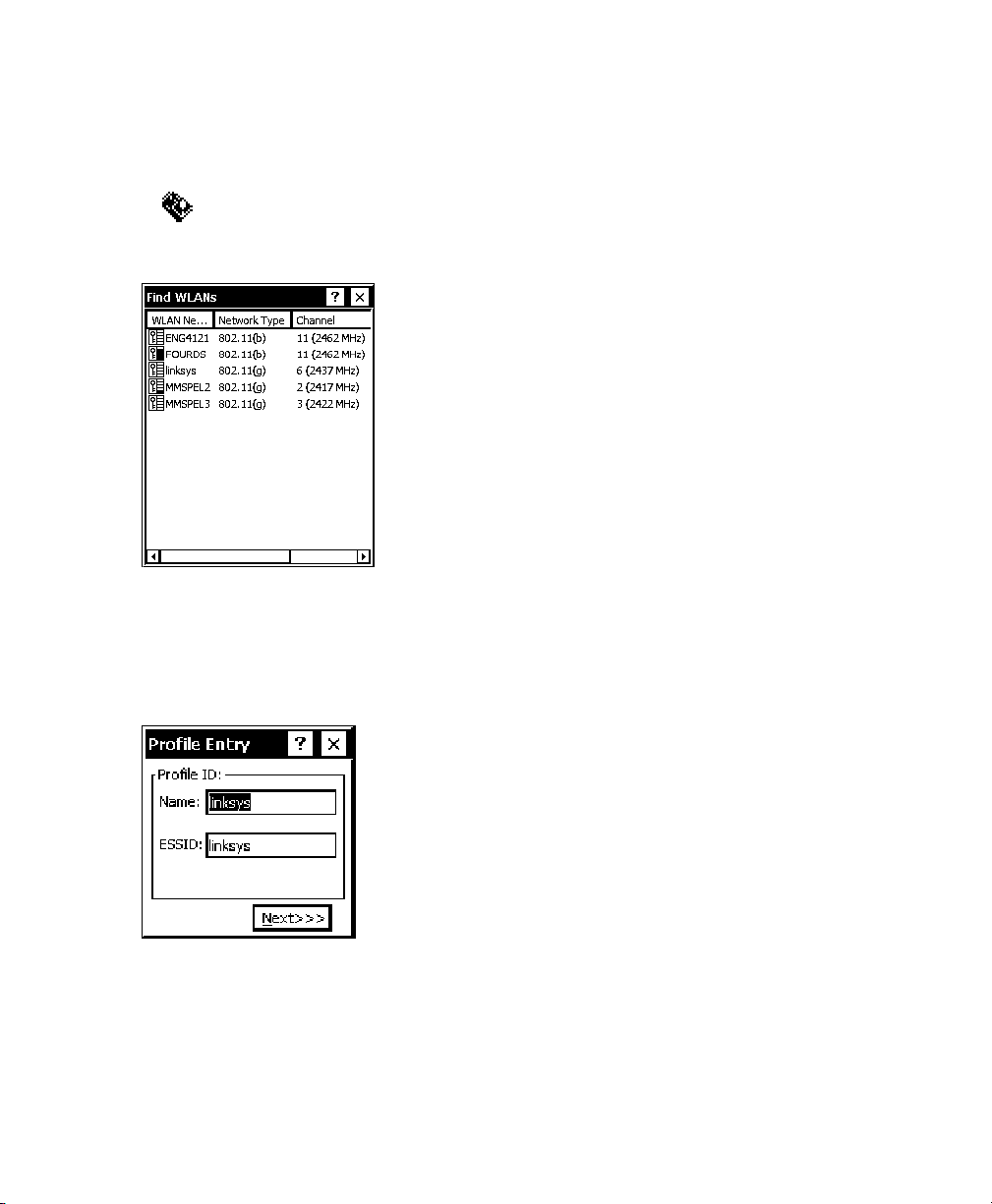
Finding a Network
The printer searches for available networks and lists the SSIDs, signal
strength, and encryption. You can connect to an existing network profile if
you have the required network security information.
1. Tap
The printer searches for all networks in range and lists them
alphabetically by SSID. This may take a few minutes.
Note: A key indicates that encryption is enabled on the access point. You
2. Double-tap the network you need, then tap Connect in the pop-up menu.
The Profile Entry screen appears.
, Find WLANs.
must have the network encryption settings to connect to a protected
access point.
3. Tap Next to verify the mode, authentication, encryption, and IP
configuration settings.
3-6 System Administrator’s Guide
Page 21

4. Tap Finished.
The Manage Profiles screen appears. When you connect to a
network, Fusion creates a profile for that connection. Your selected
profile is shown with an access point icon.
Note: The icon indicates a connection to this profile. To connect to a
different profile, double-tap on the profile name, then tap Connect in
the pop-up menu.
5. Tap X in the upper right-hand corner of the screen to return to the
desktop.
Creating a Profile
You can create a new connection profile if the network you need does not
appear in the list of available profiles.
1. Tap
2. Hold the stylus on an empty section of the screen until the pop-up menu
appears.
, Manage Profiles.
Configuring Wireless Settings 3-7
Page 22

3. Tap Add. The Profile Entry screen appears.
4. Enter a profile name and SSID to identify the printer on the network.
The default name is 101. Tap Next.
5. Specify the wireless operating mode (Ad-Hoc or Infrastructure) and your
country of operation, if necessary. Tap Next.
6. Specify the authentication security settings. The options are None,
EAP-TLS, PEAP, LEAP, or TTLS.
These settings must match the network authentication settings or the
printer cannot connect. Tap Next.
7. Specify the encryption settings. The options are Open (no security), 40or 128-bit WEP, TKIP (WPA), or AES.
These settings must match the network encryption settings or the printer
cannot connect. Tap Next.
8. Select the IP Address Entry method. The options are DHCP or Static.
Tap Next.
9. Adjust the radio transmission power, if necessary. The options for
Infrastructure mode are Automatic and Power Plus.
When using Automatic, the printer uses the same transmit power level as
the access point. When using Power Plus, the printer uses a transmit
power one level higher than that of the access point.
Tap Next.
10. Adjust the battery usage settings, if necessary.
11. Tap Finished.
Your new profile appears on the Manage Profiles
screen. If you are not automatically connected to
your new profile, double-tap your profile’s name,
then tap Connect in the pop-up menu.
3-8 System Administrator’s Guide
Page 23

Setting a Password
You can set or change the Fusion access password. The default is no
password.
Note: Make a note of the password if you change it. Setting a password
restricts all access to wireless features.
1. Tap , Options.
2. Select Change Password from the drop-down menu.
3. To enable password protection, enter and confirm a new password.
To change a current password, enter the current password, then
enter and confirm a new password.
To disable password protection, enter the current password but do
not specify a new password.
4. Tap Save, then OK.
5. Tap X in the upper-right hand corner of the screen to return to the
desktop.
Configuring Wireless Settings 3-9
Page 24

3-10 System Administrator’s Guide
Page 25

USING PRINTER DIAGNOSTICS
Use printer diagnostics to
♦ check machine totals
♦ print diagnostic labels
♦ perform sensor tests
♦ peform a printhead dot resistance test
♦ check the keyboard’s functionality.
Accessing Printer Diagnostics
1. Tap the printer icon in the System Tray.
4
Using Printer Diagnostics 4-1
Page 26

2. Tap Printer Diagnostics.
You can tap
♦ About to see the printer’s software version and other information.
Tap OK to close the About box.
♦ X in the upper-right hand corner of the screen to quit Printer Diagnostics
and return to the desktop.
4-2 System Administrator’s Guide
Page 27

Testing the Print Engine
1. Tap Print Engine Tests from the Printer Diagnostics screen.
2. Decide which of the following tests to perform:
♦ For Machine Totals, see “Checking Machine
Totals” for more information.
♦ For Diagnostic Labels, see “Printing
Diagnostic Labels” for more information.
♦ For Stock Registration, see “Checking the
Stock Registration” for more information.
♦ For Sensor Tests, see “Performing Sensor
Tests,” for more information.
♦ For the Printhead Dot Resistance, see
“Testing the Printhead,” for more
information.
♦ For the Print Engine memory expansion
directory, see “Memory Card Directory
Listing,” for more information.
The Service Diagnostics Menu can only be accessed by a Paxar
Representative because it requires a separate password.
Using Printer Diagnostics 4-1
Page 28

Checking Machine Totals
1. Tap Machine Totals from the Print Engine Tests screen. You see the
machine totals for inches printed, service inches printed, high (for
synthetic supply) inches printed, and service high inches printed.
The printer tracks how many inches of supply it prints.
2. Tap Back to return to the Print Engine Tests screen.
OR
Tap Done to return to the desktop.
4-2 System Administrator’s Guide
Page 29

Printing Diagnostic Labels
1. Tap Diagnostic Labels (test labels) from the Print Engine Tests
screen.
2. Before you run these tests, be sure to load your supply in Non-Peel
mode. Refer to the Operator’s Handbook for more information about
loading supply.
Select: The following labels print:
Information Labels
The first diagnostic (test) label shows the model
number, software version, and the printer’s
configuration by packet. Refer to the Programmer’s
Manual for more information about configuration
packets. The second diagnostic label shows the
model number, software version, total number of
inches printed, voltage, print contrast, printhead
resistance, number of bad dots, and memory.
Using Printer Diagnostics 4-3
Page 30
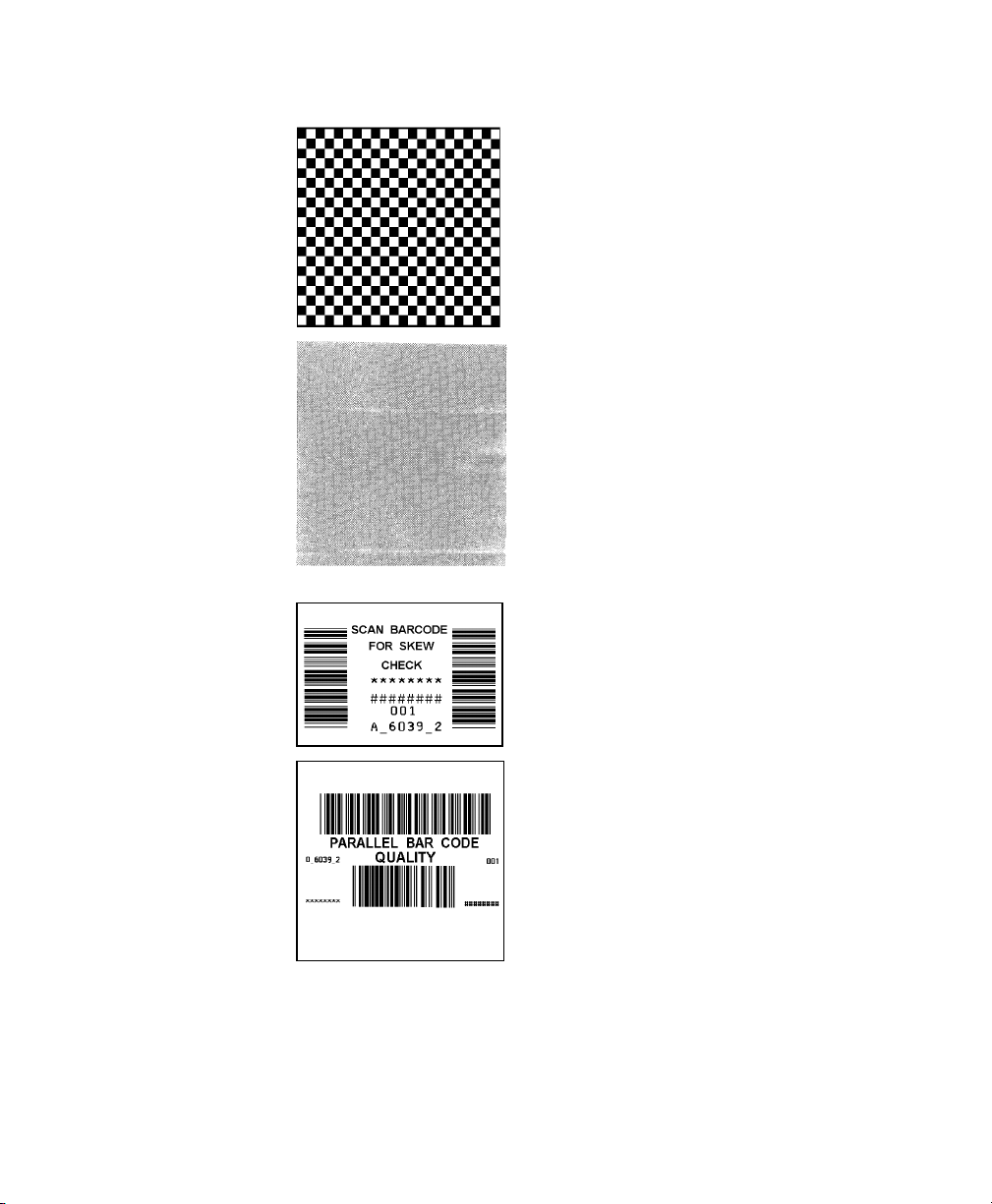
Select: The following label prints:
Checkerboard
Label
Prints a label to verify that the
printhead strobes are working. If
your printed sample has fewer
lines or no lines, keep the
sample and call Service.
Gray Scale Label The gray scale test checks the
uniformity of the printing. The
printed sample should be
uniformly gray across the
supply. If you see voids,
especially on the edges, keep
the sample and call Service.
Label with voids
Serial Quality
Label
Parallel Quality
Label
4-4 System Administrator’s Guide
A label prints bar codes for you
to scan to check the quality of
serial bar codes.
A label prints bar codes for you
to scan to check the quality of
parallel bar codes.
Page 31

Select: The following label prints:
Contrast Use the arrow keys to change the print contrast.
The higher the number, the darker the print; the
lower the number, the lighter the print.
The print contrast controls the darkness of the
printing on your supply. The range is –28 to +40 and
the default is 0. You may need to increase or
decrease the print contrast depending on your
supply type.
The correct print contrast setting affects how well
your bar codes scan and how long your printhead
lasts.
3. Tap Back to return to the Print Engine Tests screen.
OR
Tap Done to return to the desktop.
Checking the Stock Registration
1. Load the supply and feed it through the label path as shown in the
Operator’s Handbook or Quick Reference.
2. Tap Stock Registration from the Print Engine Tests screen.
Using Printer Diagnostics 4-5
Page 32

3. Select the sensor to calibrate (either Black Mark or On-Demand).
The black mark sensor is used with black mark supplies (supplies
with rectangular marks on the back side of the liner or on the supply).
The on-demand sensor is for peeled supplies, either die-cut or black
mark.
4. Tap Calibrate Sensor to calibrate the selected sensor.
If you select the Black Mark sensor, the printer feeds supply until
it detects a black mark to calibrate the sensor. When the
calibration is successful, a label prints: “Stock Sensor Calibration
Successful.”
If you select the On-Demand sensor, the printer feeds one or two
labels to calibrate the on-demand sensor.
As these tests are successfully performed, a window appears that
tells you if the calibration was successful or unsuccessful. Tap
OK.
If you calibrate the sensor, there is no need to calibrate the
supply. However, if you tap Calibrate Stock, two or three labels
are fed to calibrate the supply.
Note: If you want to feed a blank label, tap Feed.
5. Tap Back to return to the Print Engine Tests screen.
OR
Tap Done to return to the desktop.
4-6 System Administrator’s Guide
Page 33

Testing the Sensors
1. Tap Sensor Tests from the Print Engine Tests screen.
2. You see the values for battery voltage,
black mark sensor, on-demand sensor, and
printhead temperature. The battery voltage
range is between 7.0 and 8.4 volts. The
printer will not print if the voltage is below
7.0.
3. Open the cover to test the sensors.
♦ For the Black Mark sensor, hold a black
mark against the sensor as shown. When
you place the black mark on the sensor, the
values change on the screen. If white is
over the sensor, the values shown for the
sensor are higher. The range is between 0
and 5.0.
Black Mark Sensor
Place black mark on
supply over sensor.
Using Printer Diagnostics 4-7
Page 34

♦ For the On-Demand sensor, hold a white label against the sensor as
shown. When you cover the sensor with a label, the values change on
the screen. The valid range is between 3.0 and 5.0. If the sensor is
covered by a black mark, the valid range is between 0 and 1.5.
4. The value listed for PH Temperature is the current temperature of the
On-Demand Sensor
being covered by
label.
printhead. The valid range is between 5 and 60 Celsius. The
temperature of the printhead depends upon the number of labels
printed and the operating environment. If the temperature is greater
than 60, the printer will not print.
5. Tap Stop to stop the test and clear the values. Tap Start to run the
test again.
Note: If the value is not within the ranges, make a note of the values
given and call Service.
6. Tap Back to return to the Print Engine Tests screen.
OR
Tap Done to return to the desktop.
4-8 System Administrator’s Guide
Page 35

Testing the Printhead
1. Tap Printhead Dot Resistance from the Print Engine Tests screen to
perform the printhead dot resistance test.
2. The printhead test checks for dot resistance. The dot resistance test
checks each dot on the printhead. The valid range is between 245
and 455.
Note: If the values are not within range, make a note of the values
given and call Service.
3. Tap Back to return to the Print Engine Tests screen, and again to
return to the Printer Diagnostics screen
OR
Tap Done to return to the desktop.
Using Printer Diagnostics 4-9
Page 36

Viewing the Print Engine Memory Expansion Directory
1. Tap Memory Card Directory Listing from the Print Engine Tests
screen to view the Print Engine memory expansion directory.
This button is grayed out if you do not have this option in your printer.
2. You see a list of what is currently saved to your Print Engine MicroSD
card. For example:
If the MicroSD card is not present, you see
3. Tap Back to return to the Print Engine Tests screen, and again to
return to the Printer Diagnostics screen.
OR
Tap Done to return to the desktop.
4-10 System Administrator’s Guide
Page 37

Testing the Keypad
1. Tap Keypad Tests from the Printer Diagnostics screen.
2. Press the key you want to test. The key pressed appears on the
display. If you press Enter, the word “Enter” appears on the display.
3. Tap Back to return to the Printer Diagnostics screen.
OR
Tap Done to return to the desktop.
Testing the Speaker
1. Tap Speaker Test from the Printer Diagnostics screen to perform the
speaker test.
Using Printer Diagnostics 4-11
Page 38

2. Tap Run Test. While the test is performed, you hear a tone sounded
at each frequency (200 Hz – 6400 Hz). The frequencies are
displayed for each tone.
3. Tap Back to return to the Printer Diagnostics screen.
OR
Tap Done to return to the desktop.
4-12 System Administrator’s Guide
Page 39

CONFIGURING THE SCANNER
Use scanner configuration to
♦ set the scanner operating mode, trigger mode, and scanner
timeout
♦ select the .wav file for successful and unsuccessful scans
♦ enable and disable each specific bar code.
Setting Scanner Options
1. Tap the printer icon in the System Tray.
5
Configuring the Scanner 5-1
Page 40

2. Tap Scanner Configuration.
Note: Tap Restore to Defaults to return all the scanner settings to the
default values. Tap Test Settings to go to the Scanner
Diagnostics screen.
The printer automatically resets any invalid settings or ranges to
the default setting. A message appears specifying which setting
or range was reset.
3. Tap General.
4. Set the Scanner Operating Mode: Momentary, Continuous, or
Compatible. The default is compatible.
5-2 System Administrator’s Guide
Page 41

Momentary
The scanner is on when the trigger is pressed and
goes off when the trigger is released.
Continuous
The scanner is always on. A good scan causes the
scanner to reset and continue scanning.
Compatible
The scanner operates in Monarch® 6037
compatible mode, which means the scanner is on
when the trigger is pressed and goes off after a
successful scan or a predetermined timeout period.
Note: An unsuccessful scans turns off the scanner and activates the
tone (.wav file) set using the Scanner Configuration menu. A “no
scan” is interpreted as an unsuccessful scan.
5. Set the Data Receive Mode: WMCHAR or SMSCANCHAR. The
default is WMCHAR.
WM_CHAR
The application receives data by the keyboard
buffer.
SM_SCANCHAR
The application receives data by the scanner
through a special message.
6. Set the Operation of the Trigger Mode: Scan, Drop, or Forward.
The default is Forward.
Scan
Pressing the trigger turns on the scanner.
Drop
The printer ignores the trigger press and does not turn
on the scanner.
Forward
The printer passes the trigger press to the application
as an F11, which allows for more control of the
application. You can code a custom application to
perform a special function whenever it receives an F11.
7. Enable Send Scan Status to return the data after any scan. This
data precedes the bar code and includes the length of data and bar
code type. See Appendix A, “Scan Status Values,” for more
information.
8. Set the No Scan Timeout in tenths of seconds, which is the amount
of time the scanner beam is on before turning off when the trigger is
pressed. The range is 5 – 99. The default is 30.
Configuring the Scanner 5-3
Page 42

9. Tap the Page 2 tab at the top of the screen to continue. You see
additional options:
10. Set the Preamble, which specifies the characters to preface returned
data from certain bar codes. The Preamble can be up to twenty userdefined characters.
11. Set the Postamble, which is the data to be sent after each scanned
barcode. The Postamble can be up to twenty user-defined
characters.
12. Set the AIM Duration, which is the duration of the aiming beam when
the scanner is activated. The range is 0.0 - 9.9 seconds in .1-second
increments (0 disables the AIM feature). The default is 0.
13. Set the Linear Security, which is how many times to scan the same
barcode to determine a successful read. The range is 1 – 4. The
default is 1.
14. Enable Bi-Directional Redundancy, which specifies that good scans
must occur in both directions (forward and reverse) for the scan to be
complete.
5-4 System Administrator’s Guide
Page 43

15. Use Browse to select the tone (.wav file) for a Good Scan. This tone
is heard whenever a bar code is successfully scanned.
16. Tap Play to hear the tone.
17. Use Browse to select the tone (.wav file) for No Scan. This tone is
heard whenever a bar code is unsuccessfully scanned.
18. Tap Play to hear the tone.
19. Tap OK to save all the settings and return to the Scanner
Configuration screen.
Enabling Specific Bar Codes
You must enable and disable each specific bar code type for scanning.
Some bar codes require additional settings.
You can scan any of the following bar codes:
♦ UPC/EAN ♦ Codabar
♦ Code 39 ♦ Code 93
♦ Code 128 ♦ D 2of5
♦ I 2of5 ♦ RSS
♦ MSI
Note: Some bar codes can be printed, but not scanned. See “Printable
Bar Codes vs. Scannable Bar Codes” for more information.
Configuring the Scanner 5-5
Page 44
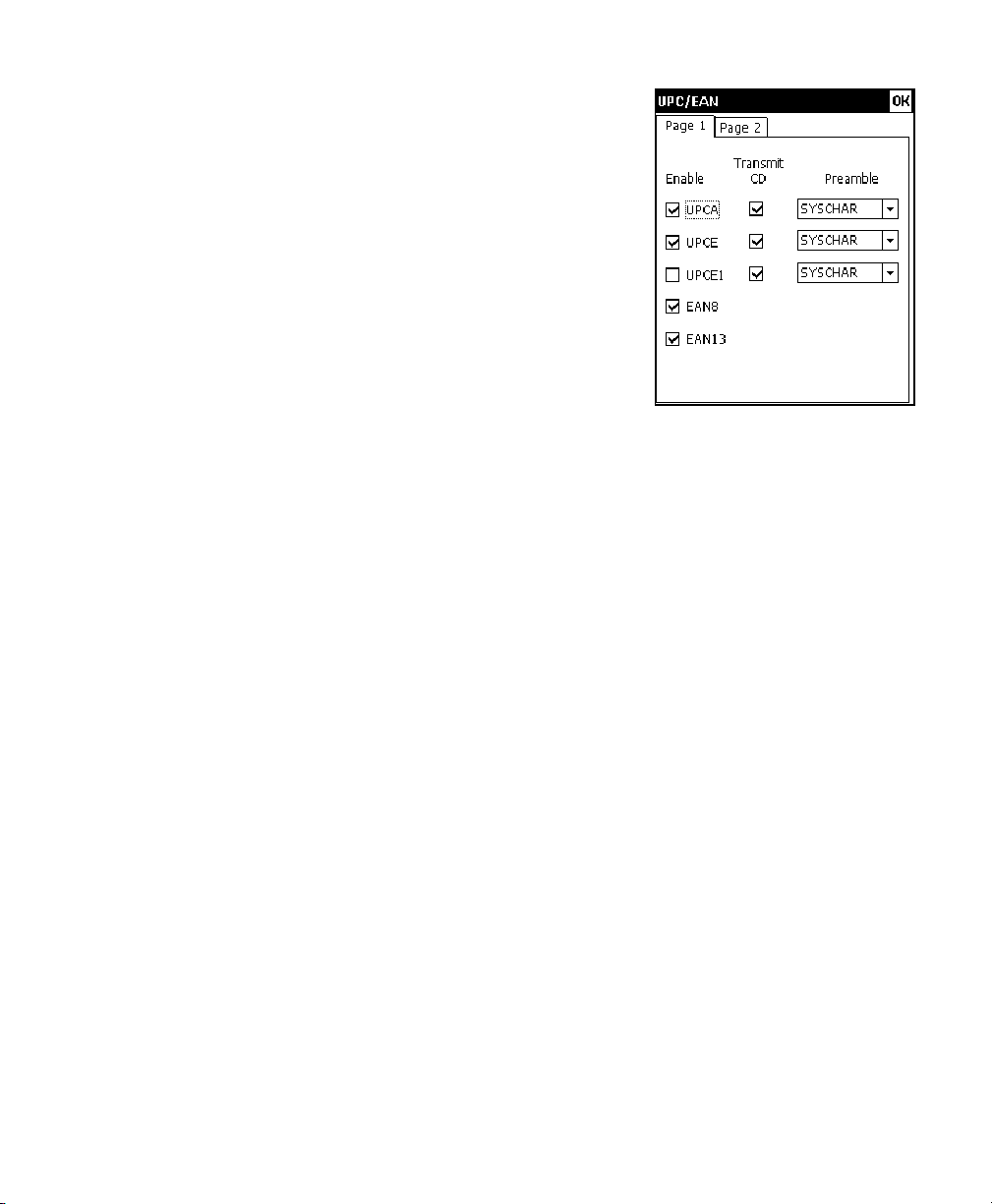
Configuring UPC/EAN Bar Codes
1. To configure UPC/EAN settings, tap UPC/EAN
from the Scanner Configuration screen.
2. Enable each bar code you need to scan.
UPCA
UPCE
UPCE1
EAN8
EAN13
3. For each bar code, decide if you want to tell the scanner to return the
check digit with the data when the bar code is scanned. Check the
Transmit CD box as necessary.
4. For each bar code, set the Preamble, which specifies the characters
that preface the returned data from a UPCA bar code. The choices
are
♦ None (No Data)
♦ SYSCHAR (System Character)
♦ SYSCOUNT (Country Code and System Character).
Note: The USA country code is 0.
Allows the scanner to scan UPCA,
UPCA+2, and UPCA+5 bar codes.
Allows the scanner to scan UPCE
bar codes.
Allows the scanner to scan UPCE1
bar codes.
Allows the scanner to scan EAN8 bar
codes.
Allows the scanner to scan EAN13
bar codes.
5-6 System Administrator’s Guide
Page 45

5. Tap the Page 2 tap at the top of the screen to
continue.
6. Enable each bar code you need to scan.
Coupon
Code
UPCE to
UPCA
EAN Zero
Extend
Bookland
EAN8 to
EAN13
UPCE1 to
UPCA
Allows the scanner to scan UPCA,
UPCA+2, UPCA+5, and UPCA/EAN128 bar codes.
Note: Set Supplemental to Auto to
use this option.
Tells the scanner to convert UPCE
bar codes to a UPCA format before
returning the data.
Note: After the conversion, your
UPCA selections affect the
data.
Tells the scanner to add 5 leading zeros to EAN8 bar codes
to convert them into EAN13 bar codes.
Allows the scanner to scan Bookland EAN bar codes.
Tells the scanner to label the bar code as EAN8 or EAN13
when EAN Zero Extend is enabled.
Tells the scanner to convert UPCE1 bar codes to a UPCA
format before returning the data.
Note: After the conversion, your UPCA selections affect the
data.
7. Set the Supplemental Mode for UPC/EAN bar codes, which specifies
how to treat UPC and EAN bar codes with supplemental characters
(UPCA+2, for example). The choices are Required, Ignore, or Auto.
The default is Ignore.
Required
Ignore
Auto
The scanner scans bar codes with supplemental characters
only. For example, it scans a UPCA+2 bar code, but not
UPCA.
The scanner ignores supplemental characters. For example,
it scans a UPCA+2 bar code as a UPCA.
Uses scanning information as specified in Scan UPC/EAN
Supplemental Redundancy.
Configuring the Scanner 5-7
Page 46

8. Set the Supplemental Redundancy, which sets the number of times
a symbol without supplemental information is decoded. The range is
2 – 20. The default is 7.
9. Set the Security, which is how many times to scan the same barcode
to determine a successful read. The range is 1 – 4. The default is 1.
Before setting this security level, you must decide the print quality
of the bar codes you are scanning. The better the quality of the
bar code, the lower the security level needed.
1
2
3
4
Choose 1 if most of your scans are successful.
Choose 2 when your unsuccessful scans are related to characters
1, 2, 7, and 8.
Choose 3 when your unsuccessful scans are not limited to
characters 1, 2, 7, and 8.
Choose 4 if unsuccessful scans still occur at level 2.
10. Tap OK to save all the settings and return to the Scanner
Configuration screen.
5-8 System Administrator’s Guide
Page 47

Configuring Code 39 Bar Codes
1. To configure Code 39 settings, tap Code 39
from the Scanner Configuration screen.
2. Enable each bar code you need to scan.
Code 39
Transmit
CD
Code32
Prefix
Allows the scanner to scan
Code 39 bar codes.
Tells the scanner to return the
check digit with the data when a
Code 39 bar code is scanned.
Allows the scanner to scan
Code 32 Prefix bar codes.
Convert to
Code32
Full ASCII
Conversion
Trioptic 39
Verify CD
Tells the scanner to convert Code 39 bar codes to Code
32 bar codes.
Allows the scanner to interpret data in a Code 39 bar code
as an ASCII representation. The scanner does not
autodiscriminate between Code 39 and Code 39 Full
ASCII.
Note: Do not enable this option and Trioptic Code 39 at
the same time.
Allows the scanner to scan Trioptic Code 39 bar codes.
The length is always 6.
Note: Do not enable this bar code and Code 39 Full ASCII
at the same time.
Tells the scanner to check the integrity of all Code 39 bar
codes that it scans.
Note: This option only works on Code 39 bar codes that
include a modulo 43 check digit.
Configuring the Scanner 5-9
Page 48

Lengths
Sets the
length(s) for
Code 39 bar
codes.
Variable, specifies that Code 39 bar codes can be any
length.
Note: Lengths include check digits.
1 Fixed, specifies a single length for valid Code 39 bar
codes. The range for Length 1 is 2 – 99.
The default is 2.
2 Fixed, specifies two lengths for valid Code 39 bar
codes. The range for Length 2 is 2 – 99.
The default is 55.
If you have enabled Code 39 Full ASCII, choose
Variable.
Note: Specifying a range of lengths increases the
likelihood of unsuccessful scans.
3. Tap OK to save all the settings and return to the Scanner
Configuration screen.
5-10 System Administrator’s Guide
Page 49

Configuring Code 128 Bar Codes
1. To configure Code 128 settings, tap
Code 128 from the Scanner Configuration
screen.
2. Enable each bar code you need to scan.
Code 128
UCC/
EAN-128
ISBT 128
Allows the scanner to scan Code
128 bar codes.
Allows the scanner to scan
UCC/EAN-128 bar codes.
Allows the scanner to scan ISBT
128 bar codes. Any length bar
code is valid.
3. Tap OK to save all the settings and return to the Scanner
Configuration screen.
Configuring the Scanner 5-11
Page 50

Configuring I 2of5 Bar Codes
1. To configure I 2of5 settings, tap I 2of5 from
the Scanner Configuration screen.
2. Enable each bar code you need to scan.
I 2of5
Transmit
CD
Convert
to
EAN13
Allows the scanner to scan I 2of5
bar codes.
Tells the scanner to return the
check digit with the data when an
I 2of5 bar code is scanned.
Tells the scanner to convert 14character I 2of5 bar codes into an
EAN13 bar code.
Verify
CD
Lengths
Sets the
length(s)
for I2 of
5 bar
codes.
For the conversion to work, the following must occur:
♦ I 2of5 bar codes must be enabled.
♦ 14 must be a valid length.
♦ The data must have a leading zero.
♦ The data must include an EAN13 check digit.
Tells the scanner to check the integrity of a scanned I 2of5
bar code to ensure it complies with either USS or OPCC
standards.
Variable, specifies that I 2of5 bar codes can be any length.
Note: Specifying a range of lengths increases the likelihood
of unsuccessful scans.
1 Fixed, specifies a single length for valid I 2of5 bar codes.
The range for Length 1 is 2 – 99. The default is 14.
2 Fixed, specifies two lengths for valid I 2of5 bar codes.
The range for Length 2 is 2 – 99. The default is 0.
3. Tap OK to save all the settings and return to the Scanner
Configuration screen.
5-12 System Administrator’s Guide
Page 51

Configuring MSI Bar Codes
1. To configure MSI settings, tap MSI from the
Scanner Configuration screen.
2. Enable each bar code you need to scan.
MSI
Transmit
CD
Mod
10/11 CD
Scheme
Allows the scanner to scan MSI bar
codes.
Tells the scanner to return the
check digit with the data when an
MSI bar code is scanned.
Tells which algorithm to use to
ensure the integrity of a two-check
digit MSI bar code.
Use 2
CDs
Lengths
Sets the
length(s)
for MSI
bar
codes.
Tells the number of check digits that MSI bar codes should
have.
Note: Check digits are not always returned with the data. If
you choose two check digits, you must choose a check
digit algorithm.
Variable, specifies that MSI bar codes can be any length.
Note: Specifying a range of lengths increases the likelihood
of unsuccessful scans.
1 Fixed, secifies a single length for valid MSI bar codes. The
range for Length 1 is 1 – 99. The default is 6.
2 Fixed, secifies two lengths for valid MSI bar codes. The
range for Length 2 is 1 – 99. The default is 55.
3. Tap OK to save all the settings and return to the Scanner
Configuration screen.
Configuring the Scanner 5-13
Page 52

Configuring Codabar Bar Codes
1. To configure Codabar settings, tap Codabar from the Scanner
Configuration screen.
2. Enable each bar code you need to scan.
Codabar
NOTISEdit
CLSIEdit
Lengths
Sets the
length(s)
for
Codabar
bar codes.
3. Tap OK to save all the settings and return to the Scanner
Configuration screen.
Allows the scanner to scan
Codabar bar codes.
Tells the scanner to strip the
start and stop characters from
scanned Codabar bar codes.
Tells the scanner to strip the
start and stop characters from
14-character Codabar bar codes
and insert spaces after the first,
fifth, and tenth characters.
Note: The 14-character length
does not include start and
stop characters.
Variable, specifies that Codabar bar codes can be any
length.
Note: Specifying a range of lengths increases the likelihood
of unsuccessful scans.
1 Fixed, specifies a single length for valid Codabar bar
codes. The range for Length 1 is 1 – 99. The default is 5.
2 Fixed, specifies two lengths for valid Codabar bar codes.
The range for Length 2 is 1 – 99. The default is 55.
5-14 System Administrator’s Guide
Page 53

Configuring Code 93 Bar Codes
1. To configure Code 93 settings, tap Code 93
from the Scanner Configuration screen.
2. Enable each bar code you need to scan.
Code 93
Lengths
Sets the
length(s)
for Code
93 bar
codes.
3. Tap OK to save all the settings and return to the Scanner
Configuration screen.
Allows the scanner to scan Code
93 bar codes.
Variable, specifies that Code 93
bar codes can be any length.
Note: Specifying a range of
lengths increases the
likelihood of unsuccessful
scans.
1 Fixed, specifies a single length for valid Code 93 bar
codes. The range for Length 1 is 2 – 99. The default is 4.
2 Fixed, specifies two lengths for valid Code 93 bar codes.
The range for Length 2 is 2 – 99. The default is 55.
Configuring the Scanner 5-15
Page 54

Configuring D 2of5 Bar Codes
1. To configure D 2of5 settings, tap D 2of5 from
the Scanner Configuration screen.
2. Enable each bar code you need to scan.
D 2of5
Lengths
Sets the
length(s)
for D
2of5 bar
codes.
3. Tap OK to save all the settings and return to the Scanner
Configuration screen.
Allows the scanner to scan D 2of5
bar codes.
Variable, specifies that D 2of5 bar
codes can be any length.
Note: Specifying a range of lengths
increases the likelihood of
unsuccessful scans.
1 Fixed, Specifies a single length for valid D 2of5 bar codes.
The range for Length 1 is 2 – 99. The default is 12.
2 Fixed, Specifies two lengths for valid D 2of5 bar codes.
The range for Length 2 is 2 – 99. The default is 0.
5-16 System Administrator’s Guide
Page 55

Configuring RSS Bar Codes
1. To configure RSS settings, tap RSS from
the Scanner Configuration screen.
2. Enable each bar code you need to scan.
RSS 14
RSS
Limited
RSS
Expanded
RSS to
UPC/EAN
3. Tap OK to save all the settings and return
to the Scanner Configuration screen.
Allows the scanner to scan RSS
14 bar codes.
Allows the scanner to scan RSS
Limited bar codes.
Allows the scanner to scan RSS
Expanded bar codes.
Tells the scanner to convert RSS
bar codes into an UPC/EAN bar
code.
Configuring the Scanner 5-17
Page 56

Printable Bar Codes vs. Scannable Bar Codes
The printer scans the following bar codes:
♦ Codabar ♦ Code 128
♦ Code 39
(MOD 43 check digit)
♦ Code 39 (no check digit) ♦ Code 93 ♦ EAN 13
♦ EAN 13 & Price CD ♦ EAN 13 +2 ♦ EAN 13 +5
♦ EAN 8 ♦ EAN 8 +2 ♦ EAN 8 +5
♦ I2 of 5 with Barrier Bar ♦ I2of5 ♦ MSI
♦ UPCA ♦ UPCA & Price CD ♦ UPCA +2
♦ UPCA +5 ♦ UPCE ♦ UPCE +2
♦ UPCE +5
The printer prints the following bar codes:
♦ Codabar ♦ Code 128
♦ Code 39 (no check digit) ♦ Code 93 ♦ EAN 13
♦ EAN 13 & Price CD ♦ EAN 13 +2 ♦ EAN 13 +5
♦ EAN 8 ♦ EAN 8 +2 ♦ EAN 8 +5
♦ I2of5 ♦ I2of5 with Barrier Bar ♦ MaxiCode
♦ MSI ♦ PDF417 ♦ Postnet
♦ UPCA ♦ UPCA +5 ♦ UPCA & Price CD
♦ UPCA +2 ♦ UPCE +5 ♦ UPCE
♦ UPCE +2
♦ Code 39
(MOD 43 check digit)
5-18 System Administrator’s Guide
Page 57

USING SCANNER
DIAGNOSTICS
Use scanner diagnostics to
♦ check the data in a bar code
♦ view a bar code’s type and length.
Performing Scanner Diagnostics
1. Tap the printer icon in the System Tray.
6
Using Scanner Diagnostics 6-1
Page 58

2. Tap Scanner Diagnostics.
3. Scan a bar code. You see the bar code’s data and length.
4. Tap About to see additional scanner information.
5. Tap OK to close the About box.
6. Tap X in the upper-right hand corner of the screen to return to the
desktop.
6-2 System Administrator’s Guide
Page 59

Setting the Scanner Mode
To set the scanner mode without using the Scanner Configuration menu:
1. Tap the printer icon in the System Tray.
2. Set the Scanner Mode: Momentary, Continuous, or Compatible.
Momentary
Continuous
Compatible
Note: A bad scan turns off the scanner and activates the tone (.wav
file) set in Scanner Configuration.
The scanner is on as long as the trigger is pressed
and goes off when the trigger is released.
The scanner is always on. A good scan causes the
scanner to reset and continue scanning.
The scanner operates in Monarch® 6037
compatible mode. The scanner is on as long as the
trigger is pressed and goes off after a successful
scan or a predetermined timeout period.
Setting the Trigger Mode
To set the trigger mode without using Scanner Configuration:
1. Tap the printer icon in the System Tray.
2. Set the Trigger Mode: Scan, Drop, or Forward. The default is
Forward.
Scan
Pressing the trigger activates the scanner.
Drop
Forward
The printer ignores the trigger press and does NOT
activate the scanner.
The printer passes the trigger press to the application,
which simulates pressing F11.
Using Scanner Diagnostics 6-3
Page 60

6-4 System Administrator’s Guide
Page 61

SCAN STATUS VALUES
If you have enabled Send Scan Status, use the following table to
interpret the data returned from every scan. This data precedes
the bar code and includes the length of data and bar code type. Refer to
the Programmer’s Manual for more information.
Value Bar Code Type
0 No Scan
1 Code 39
2 Codabar
3 Code 128
4 Dk 2of5
5 IATA 2of5
6 I 2of5
7 Code 93
8 UPC A
9 UPC E
10 EAN 8
11 EAN 13
14 MSI Plessey
15 EAN 128
16 UPC E1
21 Trioptic Code 39
22 Bookland EAN
23 Coupon Code
A
Scan Status Values A-1
Page 62

Value Bar Code Type
48 RSS 14
49 RSS Limited
50 RSS Expanded
72 UPC A with 2 Supplements
73 UPC E with 2 Supplements
74 EAN 8 with 2 Supplements
75 EAN 13 with 2 Supplements
80 UPC E1 with 2 Supplements
136 UPC A with 5 Supplements
137 UPC E with 5 Supplements
138 EAN 8 with 5 Supplements
139 EAN 13 with 5 Supplements
144 UPC E1 with 5 Supplements
A-2 System Administrator’s Guide
Page 63

Page 64

Visit for sales, service,
www.monarch.com
supplies, information, and telephone numbers
for our locations throughout the world.
TOLL FREE:
1-800-543-6650 (In the U.S.A.)
1-800-363-7525 (In Canada)
 Loading...