

Page 1
Model 2292 & 2294
Leased-Line Extenders over IP
Quick Start Guide
Important
intended nor approved for use in an industrial or residential environment.
Part Number: 07M2292-QS, Rev. A
Revised: April 13, 2009
—This is a Class A device and is intended for use in a light industrial environment. It is not
Sales Office: +1 (301) 975-1000
Technical Support: +1 (301) 975-1007
E-mail: support@patton.com
WWW: www.patton.com
Page 2
• This device contains no user serviceable parts. The equipment shall be
returned to Patton Electronics for repairs, or repaired by qualified
service personnel.
WARNING
• Mains Voltage: Do not open the case when the power cord is connected. For systems without a power switch, line voltages are
present within the power supply when the power cord is connected.
• The external power adapter shall be a listed Limited Power Source.
Ensure that the power cable used meets all applicable standards for
the country in which it is to be installed, and that it is connected to a
wall outlet which has earth ground. The mains outlet that is utilized
to power the devise shall be within 10 feet (3 meters) of the device,
shall be easily accessible, and protected by a circuit breaker.
• Hazardous network voltages are present in WAN ports regardless of
whether power to the SmartNode is ON or OFF. To avoid electric
shock, use caution when near WAN ports. When detaching cables,
detach the end away from the SmartNode first.
• Do not work on the system or connect or disconnect cables during
periods of lightning activity.
• Before opening the chassis, disconnect the telephone network cables
to avoid contact with telephone line voltages.
1.0 Installing the SmartNode extender
1.1 Mounting the SmartNode extender
Place the extender on a desktop or similar sturdy, flat surface that offers easy access to the cables. The extender
should be installed in a dry environment with sufficient space to allow air circulation for cooling.
For proper ventilation, leave at least 2 inches (5 cm) to the left, right, front, and rear of the SmartNode
extender.
1.2 Connecting cables
• Do not work on the system or connect or disconnect cables during
periods of lightning activity.
WARNING
• The Interconnecting cables shall be acceptable for external use and
shall be rated for the proper application with respect to voltage, current, anticipated temperature, flammability, and mechanical serviceability.
Install the cables in the following order:
1.
Installing the RJ-11 voice port cable or cables
(see
1.3 “Installing an interface cable on the extender’s voice ports”
2
on page 3)
Model 2292/2294 Quick Start Guide
Page 3
Ethernet connectors
Voice ports
Ports
, 1.25A
2.
Installing the 10/100 Ethernet port cable or cables
(see
1.4 “Installing the Ethernet cable”
3.
Installing the power input
(see
1.5 “Connecting to external power source”
Reset
ETH 0/1 ETH 0/0
on page 5)
on page 6)
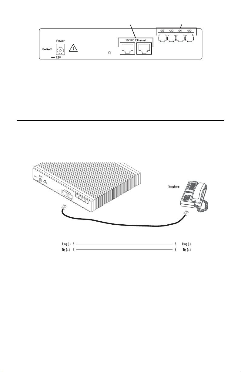
1.3 Installing an interface cable on the extender’s voice ports
The SmartNode extender comes with at least two voice ports (see
The voice ports are connected to analog devices via cables (see
nectors (see
figure 4
Figure 1.
, 1.25A
and Table 1 on page 4 for pin-out information).
Rear view showing location of Ethernet connectors and voice ports (SmartNode 2294 shown)
Reset
ETH 0/1 ETH 0/0
Ports
figure 1
figure 2
) located on the back of the extender.
and
figure 3
) terminated with RJ-11 con-
RJ-11, male RJ-11, male
Model 2292/2294 Quick Start Guide
Figure 2.
FXS connection
3
Page 4

, 1.25A
Reset
ETH 0/1 ETH 0/0
Ports
PSTN
wall plate
RJ-11, male RJ-11, male
Figure 3.
4
9
2
2
P
I
e
r
d
e
o
v
O
N
t
r
r
e
a
d
n
m
e
t
S
x
E
e
n
i
L
-
d
e
s
a
e
L
Console
0/3
0/2
0/1
0/0
ts
r
o
P
Activity
100M
Link
t 1
e
n
E
Activity
100M
Link
t 0
e
n
E
VoIP Link
Run
Power
Figure 4.
Table 1.
Pin
FXO connection
654321
Socket
RJ-11 pinout diagram
RJ-11 socket
123456
Plug
Signal
3 Ring (-)
4 Tip (+)
Note
Unit must not connect directly to telecom network voltage (TNV).
4
Model 2292/2294 Quick Start Guide
Page 5

1.4 Installing the Ethernet cable
The SmartNode 2292 Series has automatic MDX (auto-cross-over) detection and configuration on the Ethernet
ports. Any of the two ports can be connected to a host or hub/switch with a straight-through wired cable (see
figure 5
). Ethernet devices (10Base-T or 100Base-T) are connected to the SmartNode’s Ethernet ports (see
table 2
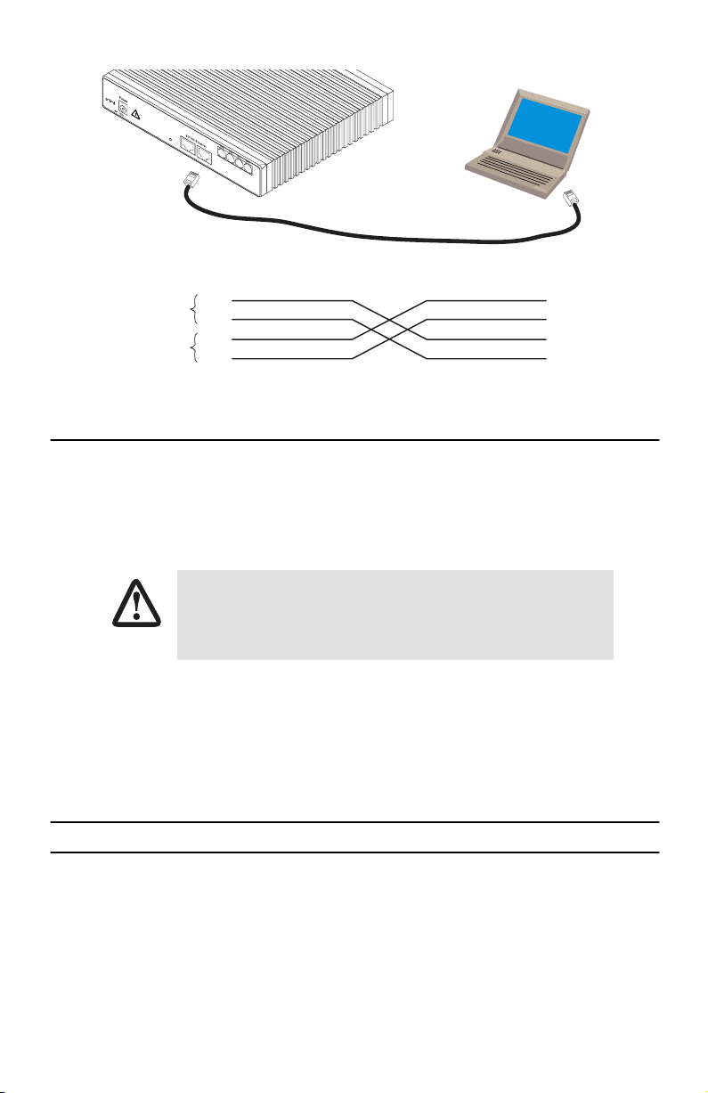
for port pin-out listing) via a cable terminated with RJ-45 plugs. Because the SmartNode 2294 Series
does not have the MDX feature, a cross-over cable is required when connecting SmartNode 2294 Series devices
to a host (see
figure 6
Table 2.
Note
Pins not listed are not used.
, 1.25A
Reset
).
Ethernet 10/100Base-T (RJ-45) port pin-outs (SmartNode 2294 Series)
ETH 0/1
ETH 0/0
RJ-45, male
Tx+
TxRx+
Rx-
Pin
1 TX+
2 TX3 RX+
6 RX-
Ports
Straight-through cable
1
2
3
6
Signal
Hub
RJ-45, male
1 Rx+
2 Rx3 Tx+
6 Tx-
Figure 5.
Model 2292/2294 Quick Start Guide
Connecting a SmartNode 2294 Series device to a hub
5
Page 6
, 1.25A
Reset
ETH 0/1 ETH 0/0
Ports
Host
Cross-over cable
RJ-45, male
1 TX+
2 TX3 RX+
6 RX-
Twisted pair 1
Twisted pair 2
RJ-45, male
1
Tx+
2
Tx-
3
Rx+
6
Rx-
Figure 6.
Connecting to a host
1.5 Connecting to external power source
The extender comes with an external power supply. This section describes installing the power cord into the
extender. Do the following:
Note
Do not connect the power cord to the power outlet at this time.
1.
Insert the barrel type connector end of the AC power cord into the external power supply connector.
The extender power supply automatically adjusts to accept an input voltage from 100
to 240 VAC (50/60 Hz).
Verify that the proper voltage is present before plugging the power cord into the
CAUTION
2.
Verify that the AC power cord included with your extender is compatible with local standards. If it is not,
receptacle. Failure to do so could result in equipment damage.
contact Patton to find out how to replace it with a compatible power cord.
3.
Connect the male end of the power cord to an appropriate power outlet.
4.
Verify that the green
Power
LED is lit.
2.0 Configuring the SmartNode extender
Patton SmartNodes can be used for a wide variety of IP-based network applications. To support and ease the
configuration of the SmartNodes configuration, templates for the most important applications are available on
the Patton server at www.patton.com/voip.
The main steps for setting up a new SmartNode are shown in
6
figure 7
.
Model 2292/2294 Quick Start Guide
Page 7

Configure IP address
1
100M
Link
1
t
e
n
E
Activity
100M
Link
0
t
e
n
E
VoIP Link
Run
Power
Connect the SmartNode to the network
2
Activity
0/3
0/2
0/1
0/0
s
t
r
o
P
4
9
2
2
P
I
e
r
d
e
o
v
O
N
t
r
r
e
a
d
n
m
e
t
S
x
E
e
n
i
L
d
e
s
a
e
L
Console
Console port
Serial
interface
PC or workstation
with VT-100
emulation terminal
Load configuration
3
Ethernet interface
ETH0
4
9
2
2
P
I
e
r
d
e
o
v
O
N
t
r
r
e
a
d
n
m
e
t
S
x
E
e
n
i
L
d
e
s
a
e
L
Console
0/3
0/2
0/1
0/0
s
t
r
o
P
Activity
100M
Link
1
t
e
n
E
Activity
100M
Link
0
t
e
n
E
VoIP Link
Run
Power
3. Load configuration
4
9
2
2
P
I
e
r
d
e
o
v
O
N
t
r
r
e
a
d
n
m
e
t
S
x
E
e
n
i
L
d
e
s
a
e
L
Console
0/3
0/2
0/1
0/0
s
t
r
o
P
Activity
100M
Link
1
t
e
n
E
Activity
100M
Link
0
t
e
n
E
VoIP Link
Run
Power
1. Download configuration example
PC or workstation
or VT-100 emulation
terminal
2. Modify configuration
Internet
Note
You can manually configure the
SmartNode. You do not have to load a
configuration file.
Figure 7.
Steps for setting up a new SmartNode
Patton Web server
with configuration examples
2.1 Configure the IP address
Power connection and default configuration
First the SmartNode must be connected to the mains power supply with the power cable. Wait until the 'Run' LED
stops blinking and lights constantly. Now the SmartNode is ready.
The factory default configuration for the Ethernet interface IP addresses and network masks are listed in
Table 3.
Interface Ethernet 0 (ETH0)
Interface Ethernet 1 (ETH1)
Factory default IP address and network mask configuration
IP Address
DHCP DHCP
192.168.1.1 255.255.255.0
Network Mask
table 3
Both Ethernet interfaces are activated upon power-up.
.
Model 2292/2294 Quick Start Guide
7
Page 8

Connect with the serial interface
The
Console
port is wired as an EIA-561, RS-232 port. Use the included Model 16F-561 adapter and cable (see
figure 8
) between the SmartNode’s
Console
port and a PC or workstation’s RS-232 serial interface. Activate the
terminal emulation program on the PC or workstation that supports the serial interface (e.g. HyperTerm).
0/3
0/2
0/1
0/0
s
t
r
o
P
Activity
100M
Link
1
t
e
n
E
Activity
100M
Link
0
t
e
n
E
VoIP Link
Run
Power
Terminal emulation program settings:
9600 baud
•
no parity
•
8 bit
•
•
1 stop bit
•
1 start bit
•
No flow control
P
I
r
e
v
O
r
e
d
n
e
t
SmartNode 2294
x
E
e
n
i
L
-
d
e
s
a
e
L
Console
Figure 8.
Serial Terminal
Note A Patton Model 16F-561 RJ45 to DB-9 adapter is included with
each SmartNode Series device
Connecting to the terminal
8
Model 2292/2294 Quick Start Guide
Page 9

2.2 Login
1.
Accessing your SmartNode via the local console port (or via a Telnet session) causes the login screen to
display. Type the factory default login:
administrator
and leave the password empty. Press the
after the password prompt.
login:administrator
password: <Enter>
172.16.40.1>
2.
After you have successfully logged in you are in the operator execution mode, indicated by > as command line prompt. With the commands
172.16.40.1>enable
172.16.40.1#configure
172.16.40.1(cfg)#
3.
Enter the following commands for the first SmartNode 229x device in the pair:
Copy nvram:a-side-config startup-config
Copy running-config startup-config
4.
Follow the same procedure for the other SmartNode 229x device in the pair:
Copy nvram:b-side-config startup-config
Copy running-config startup-config
Note
The configuration above is only a sample configuration that you may use as an example. You should
specify your own parameters such as your IP address and other related information as required. For
detailed information about configuring and operating your SmartNode, set-up procedures, and troubleshooting, refer to the
came with your unit.
SmartNode Series SmartWare Software Configuration Guide
enable
and
configure
you enter the configuration mode.
on the CD-ROM that
Enter
key
5.
Reboot both units and connect them back-to-back through their Ethernet 0/1 ports. Voice connections will
automatically be set up between the units.
The steps above will configure the IP addresses as well as the required configurations for voice connections.
Model 2292/2294 Quick Start Guide
9
Page 10

3.0 Additional Information
Refer to the
able online at
•
•
Model 2292/2294 Getting Started Guide
www.patton.com/manuals.
located on the CD-ROM shipped with your device and avail-
For detailed information about:
Installing, configuring, operating, and troubleshooting.
Warranty, trademark & compliance
A.0 Customer and Technical Support
Toll-Free VoIP support: call
Online support: www
E-mail support:
support@patton.com
Telephone support:
•
Standard: +1 (301) 975-1007 (USA), Monday–Friday: 8:00 am to 5:00 pm EST (1300 to
2200 UTC/GMT)
•
Alternate: +41 (0)31 985 25 55 (Switzerland), Monday–Friday: 8:00 am to 5:00 pm CET (0900 to 1800
UTC/GMT)
Fax:
+1 (253) 663-5693
sip:support@patton.com
.patton.com
—answered within 1 business day
(USA)
or +41 (0)31 985 25 26 (
with a VoIP SIP client
Switzerland)
10
Model 2292/2294 Quick Start Guide
Page 11

B.0 Compliance Information
B.1 Compliance
EMC Compliance:
•
EN55022, Class A
EN55024
•
Safety Compliance:
•
EN60950
B.2 CE Declaration of Conformity
This equipment conforms to the requirements of Council Directive 1999/5/EC on the approximation of the laws
of the member states relating to Radio and Telecommunication Terminal Equipment and the mutual recognition
of their conformity.
The safety advice in the documentation accompanying this product shall be obeyed. The conformity to the above
directive is indicated by CE sign on the device.
The signed Declaration of Conformity can be downloaded at www.patton.com/certifications.
Model 2292/2294 Quick Start Guide
11
Page 12

Copyright statement
Copyright © 2009, Patton Electronics Company. All rights reserved.
The information in this document is subject to change without notice. Patton Electronics assumes no
liability for errors that may appear in this document.
Trademarks statement
The term
SmartNode
is a trademark of Patton Electronics Company. All other trademarks presented in this docu-
ment are the property of their respective owners.
Warranty
For warranty information, refer to the
with your device or available online at
In accordance with the requirements of council directive 2002/96/EC on Waste of
Electrical and Electronic Equipment (WEEE), ensure that at end-of-life you separate
this product from other waste and scrap and deliver to the WEEE collection system in
your country for recycling.
Model 2292/2294 Getting Started Guide
www.patton.com
.
located on the CD-ROM that came
12
Model 2292/2294 Quick Start Guide
 Loading...