

Patton SmartNode 4830 DSL Series, SmartNode 4838, SmartNode 4832, SmartNode 4836, SmartNode 4834 User Manual
Page 1
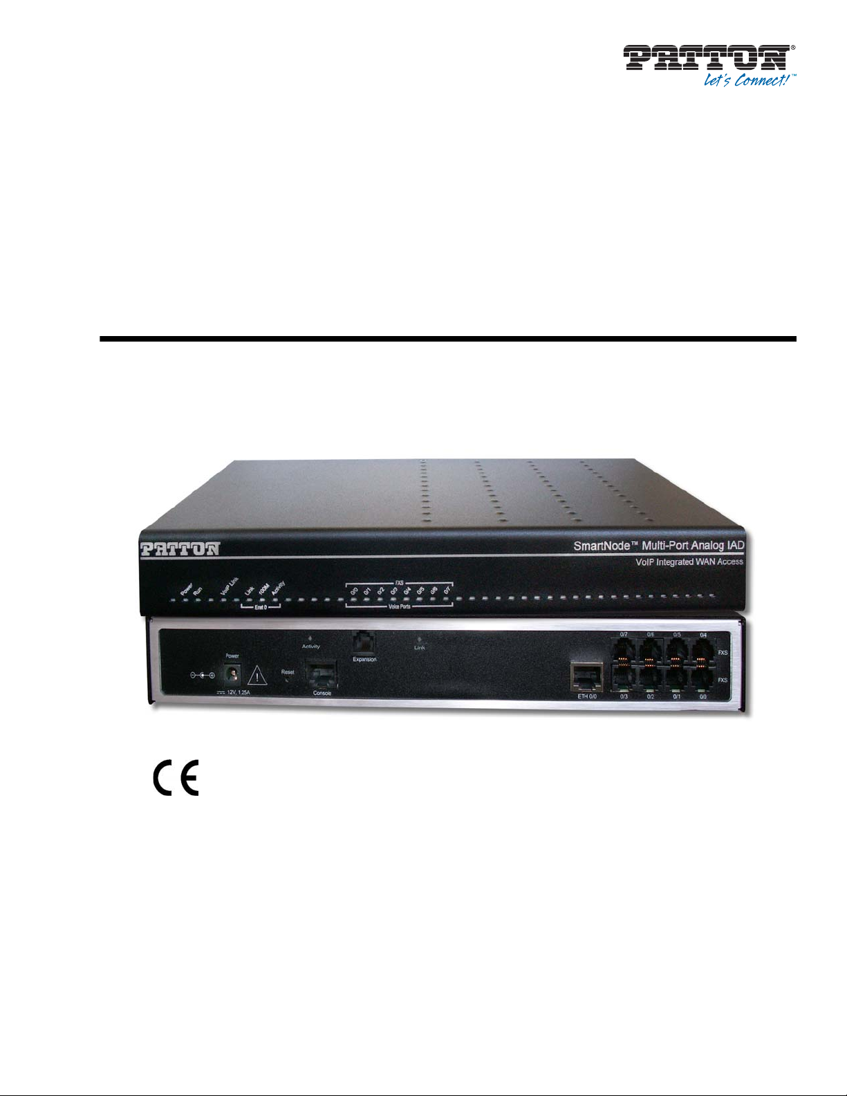
SmartNode 4830 DSL Series
Analog VoIP Integrated Access
Device
User Manual
Approval
Models that are equipped with telecom interfaces have been approved for connection to the public
telecommunication network as listed under PSTN regulatory compliance.
Important
This is a Class A device and is intended for use in a light industrial environment. It is not intended
nor approved for use in an industrial or residential environment.
Sales Office: +1 (301) 975-1000
Technical Support: +1 (301) 975-1007
E-mail: [email protected]
WWW: www.patton.com
Part Number: 07MSN4830DSL-UM, Rev. C
Revised: November 21, 2013
Page 2

Patton Electronics Company, Inc.
7622 Rickenbacker Drive
Gaithersburg, MD 20879 USA
Tel: +1 (301) 975-1000
Fax: +1 (301) 869-9293
Support: +1 (301) 975-1007
URL: www.patton.com
E-Mail: [email protected]
Trademark Statement
The terms SmartWare and SmartNode are trademarks of Patton Electronics Company.
All other trademarks presented in this document are the property of their
respective owners.
Copyright © 2012, Patton Electronics Company. All rights reserved.
The information in this document is subject to change without notice. Patton Elec-
tronics assumes no liability for errors that may appear in this document.
Warranty Information
The software described in this document is furnished under a license and may be used
or copied only in accordance with the terms of such license. For information about the
license, go to www.patton.com.
Patton Electronics warrants all SmartNode product components to be free from
defects, and will—at our option—repair or replace the product should it fail within
one year from the first date of the shipment.
This warranty is limited to defects in workmanship or materials, and does not cover
customer damage, abuse or unauthorized modification. If the product fails to perform
as warranted, your sole recourse shall be repair or replacement as described above.
Under no condition shall Patton Electronics be liable for any damages incurred by the
use of this product. These damages include, but are not limited to, the following: lost
profits, lost savings and incidental or consequential damages arising from the use of or
inability to use this product. Patton Electronics specifically disclaims all other warran-
ties, expressed or implied, and the installation or use of this product shall be deemed
an acceptance of these terms by the user.
Page 3

Summary Table of Contents
1 General information...........................................................................................................................................16
2 Hardware installation........................................................................................................................................22
3 Getting started with the SmartNode.................................................................................................................32
4 DSL Basic Configuration...................................................................................................................................41
5 Contacting Patton for assistance.......................................................................................................................46
A Compliance information ...................................................................................................................................49
B Specifications .....................................................................................................................................................53
C Cabling ...............................................................................................................................................................60
D Port pin-outs ......................................................................................................................................................66
E Installation checklist .........................................................................................................................................69
3
Page 4

Table of Contents
Summary Table of Contents ...............................................................................................................................3
Table of Contents ................................................................................................................................................4
List of Figures ......................................................................................................................................................7
List of Tables ........................................................................................................................................................8
About this guide ...................................................................................................................................................9
Audience............................................................................................................................... ................................. 9
Structure ................................................................................................................................................................ 9
Precautions .......................................................................................................................................................... 10
Safety when working with electricity ............................................................................................................11
General observations .....................................................................................................................................13
Typographical conventions used in this document............................................................................................. 14
General conventions ......................................................................................................................................15
1 General information...........................................................................................................................................16
SmartNode Model 4830 DSL Series Overview...................................................................................................17
Rear Panel ......................................................................................................................................................18
Port Descriptions ......................................................................................................................................19
Reset button behavior ..............................................................................................................................19
Model Versions ........................................................................................................................................20
Front Panel .....................................................................................................................................................20
2 Hardware installation........................................................................................................................................22
Planning the installation.......................................................................................................................................23
Installation checklist ......................................................................................................................................24
Site log ...........................................................................................................................................................25
Network information .....................................................................................................................................25
Network Diagram .....................................................................................................................................25
IP related information ....................................................................................................................................25
Software tools ................................................................................................................................................25
Power source ..................................................................................................................................................26
Location and mounting requirements ............................................................................................................26
Installing the VoIP IAD.......................................................................................................................................26
Mounting the VoIP IAD ................................................................................................................................26
Connecting cables ..........................................................................................................................................26
Installing an interface cable on the VoIP IAD’s FXS and FXO interface ports ......................................27
Installing the Ethernet cable .....................................................................................................................29
Installing the DSL cable ...........................................................................................................................30
Connecting to external power source
3 Getting started with the SmartNode.................................................................................................................32
Introduction..........................................................................................................................................................33
1. Configure IP address........................................................................................................................................34
.......................................................................................................31
4
Page 5

SmartNode 4830 DSL Series User Manual
Power connection and default configuration .................................................................................................34
Connect with the PC’s serial interface ...........................................................................................................34
Login ..............................................................................................................................................................35
Changing the IP address ................................................................................................................................35
2. Connect the SmartNode to the network...........................................................................................................36
3. Load configuration...........................................................................................................................................36
Bootloader............................................................................................................................................................37
Start Bootloader .............................................................................................................................................37
Start-up with factory configuration ...............................................................................................................38
Load a new application image (SmartWare) via TFTP .................................................................................38
Load a new application image (SmartWare) via the serial link .....................................................................40
Additional information.........................................................................................................................................40
4 DSL Basic Configuration...................................................................................................................................41
Introduction..........................................................................................................................................................42
Line Setup ............................................................................................................................................................42
Configuring PPPoE ..............................................................................................................................................42
Configuration Summary.......................................................................................................................................43
Setting up permanent virtual circuits (PVC)........................................................................................................44
Using PVC channels in bridged Ethernet mode ............................................................................................44
Using PVC channels with PPPoE ..................................................................................................................44
Diagnostics ....................................................................................................................................................45
Troubleshooting DSL Connections......................................................................................................................45
5 Contacting Patton for assistance.......................................................................................................................46
Introduction..........................................................................................................................................................47
Contact information..............................................................................................................................................47
Patton support headquarters in the USA ........................................................................................................47
Alternate Patton support for Europe, Middle East, and Africa (EMEA) .......................................................47
Warranty Service and Returned Merchandise Authorizations (RMAs)...............................................................47
Warranty coverage .........................................................................................................................................48
Out-of-warranty service ...........................................................................................................................48
Returns for credit .....................................................................................................................................48
Return for credit policy ............................................................................................................................48
RMA numbers ...............................................................................................................................................48
Shipping instructi ons ...............................................................................................................................48
A Compliance information ...................................................................................................................................49
Compliance...........................................................................................................................................................50
EMC compliance: ..........................................................................................................................................50
Safety compliance:
.........................................................................................................................................50
PSTN regulatory compliance: ........................................................................................................................50
Radio and TV Interference (FCC Part 15)...........................................................................................................50
FCC Part 68 (ACTA) Statement (FXO ports)......................................................................................................51
Industry Canada Notice (FXO ports)...................................................................................................................51
CE Notice.............................................................................................................................................................52
5
Page 6

SmartNode 4830 DSL Series User Manual
Authorized European Representative...................................................................................................................52
B Specifications .....................................................................................................................................................53
DSP.......................................................................................................................................................................54
Voice connectivity................................................................................................................................................54
Ethernet interface .................................................................................................................................................54
ADSL Daughter Card (if applicable)...................................................................................................................54
G.SHDSL Daughter Card (if applicable).............................................................................................................55
PPP and Frame-Relay support..............................................................................................................................55
Voice processing (signaling dependent) ..............................................................................................................56
Fax and modem support .......................................................................................................................................56
Voice signaling.....................................................................................................................................................56
Voice routing—session product...........................................................................................................................57
IP services ............................................................................................................................................................57
Management.........................................................................................................................................................57
Operating environment.........................................................................................................................................58
Operating temperature ...................................................................................................................................58
Operating humidity ........................................................................................................................................58
System..................................................................................................................................................................58
Dimensions...........................................................................................................................................................58
Weight and power dissipation..............................................................................................................................58
Power supply........................................................................................................................................................58
Identification of the SmartNode devices via SNMP............................................................................................59
C Cabling ...............................................................................................................................................................60
Introduction..........................................................................................................................................................61
Serial console.......................................................................................................................................................61
Ethernet 10Base-T and 100Base-T......................................................................................................................62
Analog FXS..........................................................................................................................................................63
Analog FXO.........................................................................................................................................................64
DSL......................................................................................................................................................................65
D Port pin-outs ......................................................................................................................................................66
Introduction..........................................................................................................................................................67
Console port .........................................................................................................................................................67
Ethernet 10Base-T and 100Base-T port...............................................................................................................67
FXS port...............................................................................................................................................................68
FXO port ..............................................................................................................................................................68
ADSL/G.SHDSL Port (RJ-45 )
.............................................................................................................................68
E Installation checklist .........................................................................................................................................69
Introduction..........................................................................................................................................................70
6
Page 7

List of Figures
1 SmartNode 4838 with DSL shown . . . . . . . . . . . . . . . . . . . . . . . . . . . . . . . . . . . . . . . . . . . . . . . . . . . . . . . . . . 17
2 SmartNode 4830 DSL Series connectors . . . . . . . . . . . . . . . . . . . . . . . . . . . . . . . . . . . . . . . . . . . . . . . . . . . . . 18
3 SmartNode 4830 DSL Series front panel . . . . . . . . . . . . . . . . . . . . . . . . . . . . . . . . . . . . . . . . . . . . . . . . . . . . . 20
4 Rear view showing location of Ethernet and FXS connectors (SmartNode 4838 shown) . . . . . . . . . . . . . . . . . 27
5 Analog FXS connection . . . . . . . . . . . . . . . . . . . . . . . . . . . . . . . . . . . . . . . . . . . . . . . . . . . . . . . . . . . . . . . . . . 27
6 RJ-11 pinout diagram . . . . . . . . . . . . . . . . . . . . . . . . . . . . . . . . . . . . . . . . . . . . . . . . . . . . . . . . . . . . . . . . . . . . 28
7 Analog FXO connection . . . . . . . . . . . . . . . . . . . . . . . . . . . . . . . . . . . . . . . . . . . . . . . . . . . . . . . . . . . . . . . . . . 29
8 Connecting a SmartNode 4830 DSL Series device to a hub . . . . . . . . . . . . . . . . . . . . . . . . . . . . . . . . . . . . . . . 30
9 Power connector location on rear panel . . . . . . . . . . . . . . . . . . . . . . . . . . . . . . . . . . . . . . . . . . . . . . . . . . . . . . 31
10 Steps for setting up a new SmartNode . . . . . . . . . . . . . . . . . . . . . . . . . . . . . . . . . . . . . . . . . . . . . . . . . . . . . . . 33
11 Connecting to the terminal . . . . . . . . . . . . . . . . . . . . . . . . . . . . . . . . . . . . . . . . . . . . . . . . . . . . . . . . . . . . . . . . 34
12 Connecting the SmartNode to the network . . . . . . . . . . . . . . . . . . . . . . . . . . . . . . . . . . . . . . . . . . . . . . . . . . . 36
13 Configuring the G.SHDSL card for PPPoE . . . . . . . . . . . . . . . . . . . . . . . . . . . . . . . . . . . . . . . . . . . . . . . . . . . 42
14 Connecting a serial terminal . . . . . . . . . . . . . . . . . . . . . . . . . . . . . . . . . . . . . . . . . . . . . . . . . . . . . . . . . . . . . . . 61
15 Ethernet straight-through . . . . . . . . . . . . . . . . . . . . . . . . . . . . . . . . . . . . . . . . . . . . . . . . . . . . . . . . . . . . . . . . . 62
16 Connecting an FXS device . . . . . . . . . . . . . . . . . . . . . . . . . . . . . . . . . . . . . . . . . . . . . . . . . . . . . . . . . . . . . . . . 63
17 Connecting to an FXO line socket . . . . . . . . . . . . . . . . . . . . . . . . . . . . . . . . . . . . . . . . . . . . . . . . . . . . . . . . . . 64
18 Connecting the DSL cable . . . . . . . . . . . . . . . . . . . . . . . . . . . . . . . . . . . . . . . . . . . . . . . . . . . . . . . . . . . . . . . . 65
19 EIA-561 (RJ-45 8-pin) port . . . . . . . . . . . . . . . . . . . . . . . . . . . . . . . . . . . . . . . . . . . . . . . . . . . . . . . . . . . . . . . 67
7
Page 8

List of Tables
1 General conventions . . . . . . . . . . . . . . . . . . . . . . . . . . . . . . . . . . . . . . . . . . . . . . . . . . . . . . . . . . . . . . . . . . . . 15
2 Rear panel ports . . . . . . . . . . . . . . . . . . . . . . . . . . . . . . . . . . . . . . . . . . . . . . . . . . . . . . . . . . . . . . . . . . . . . . . . 19
3 SmartNode 4830 DSL Series Model Codes . . . . . . . . . . . . . . . . . . . . . . . . . . . . . . . . . . . . . . . . . . . . . . . . . . 20
4 SmartNode LED Indications . . . . . . . . . . . . . . . . . . . . . . . . . . . . . . . . . . . . . . . . . . . . . . . . . . . . . . . . . . . . . . 21
5 Installation checklist . . . . . . . . . . . . . . . . . . . . . . . . . . . . . . . . . . . . . . . . . . . . . . . . . . . . . . . . . . . . . . . . . . . . 24
6 Sample site log entries . . . . . . . . . . . . . . . . . . . . . . . . . . . . . . . . . . . . . . . . . . . . . . . . . . . . . . . . . . . . . . . . . . . 25
7 RJ-11 socket . . . . . . . . . . . . . . . . . . . . . . . . . . . . . . . . . . . . . . . . . . . . . . . . . . . . . . . . . . . . . . . . . . . . . . . . . . 28
8 Ethernet 10/100Base-T (RJ-45) port pin-outs . . . . . . . . . . . . . . . . . . . . . . . . . . . . . . . . . . . . . . . . . . . . . . . . . 29
9 Factory default IP address and network mask configuration . . . . . . . . . . . . . . . . . . . . . . . . . . . . . . . . . . . . . 34
10 PVC Commands . . . . . . . . . . . . . . . . . . . . . . . . . . . . . . . . . . . . . . . . . . . . . . . . . . . . . . . . . . . . . . . . . . . . . . . 44
11 PVC channels in bridged Ethernet mode . . . . . . . . . . . . . . . . . . . . . . . . . . . . . . . . . . . . . . . . . . . . . . . . . . . . . 44
12 PVC channels in PPPoE mode . . . . . . . . . . . . . . . . . . . . . . . . . . . . . . . . . . . . . . . . . . . . . . . . . . . . . . . . . . . . 44
13 Diagnostics commans . . . . . . . . . . . . . . . . . . . . . . . . . . . . . . . . . . . . . . . . . . . . . . . . . . . . . . . . . . . . . . . . . . . 45
14 G.SHDSL Daughter Card Specifications . . . . . . . . . . . . . . . . . . . . . . . . . . . . . . . . . . . . . . . . . . . . . . . . . . . . 55
15 SmartNode weight and maximum power specifications . . . . . . . . . . . . . . . . . . . . . . . . . . . . . . . . . . . . . . . . . 58
16 SmartNode Models and their Unique sysObjectID . . . . . . . . . . . . . . . . . . . . . . . . . . . . . . . . . . . . . . . . . . . . . 59
17 RJ-45 socket . . . . . . . . . . . . . . . . . . . . . . . . . . . . . . . . . . . . . . . . . . . . . . . . . . . . . . . . . . . . . . . . . . . . . . . . . . 67
18 RJ-11 socket . . . . . . . . . . . . . . . . . . . . . . . . . . . . . . . . . . . . . . . . . . . . . . . . . . . . . . . . . . . . . . . . . . . . . . . . . . 68
19 RJ-11 socket . . . . . . . . . . . . . . . . . . . . . . . . . . . . . . . . . . . . . . . . . . . . . . . . . . . . . . . . . . . . . . . . . . . . . . . . . . 68
20 RJ-45 DSL port . . . . . . . . . . . . . . . . . . . . . . . . . . . . . . . . . . . . . . . . . . . . . . . . . . . . . . . . . . . . . . . . . . . . . . . . 68
21 Installation checklist . . . . . . . . . . . . . . . . . . . . . . . . . . . . . . . . . . . . . . . . . . . . . . . . . . . . . . . . . . . . . . . . . . . . 70
8
Page 9

About this guide
This guide describes the SmartNode 4830 hardware, installation and basic configuration. For detailed software
configuration information refer to the SmartWare Software Configuration Guide and the available Configura-
tion Notes.
Audience
This guide is intended for the following users:
• Operators
• Installers
• Maintenance technicians
Structure
This guide contains the following chapters and appendices:
• Chapter 1 on page 16 provides information about product features and capabilities
• Chapter 2 on page 22 provides hardware installation procedures
• Chapter 3 on page 32 provides quick-start procedures for configuring the SmartNode product
• Chapter 4 on page 41 provides information on configuring DSL
• Chapter 5 on page 46 contains information on contacting Patton technical support for assistance
• Appendix A on page 49 contains compliance information
• Appendix B on page 53 contains specifications for the products
• Appendix C on page 60 provides cable recommendations
• Appendix D on page 66 describes the product’s ports and pin-outs
• Appendix E on page 69 provides an installation checklist for the SmartNode 4830
For best results, read the contents of this guide before you install the product.
9
Page 10
SmartNode 4830 DSL Series User Manual About this guide
IMPORTANT
CAUTION
CAUTION
WARNING
WARNING
Precautions
Notes, cautions, and warnings, which have the following meanings, are used throughout this guide to help you
become aware of potential problems. War ni ngs are intended to prevent safety hazards that could result in personal injury. Cautions are intended to prevent situations that could result in property damage or
impaired functioning.
Note A note presents additional information or interesting sidelights.
The alert symbol and IMPORTANT heading calls attention to
important information.
The alert symbol and CAUTION heading indicate a potential hazard. Strictly follow the instructions to avoid property damage.
The shock hazard symbol and CAUTION heading indicate a
potential electric shock hazard. Strictly follow the instructions to
avoid property damage caused by electric shock.
The alert symbol and WARNING heading indicate a potential safety hazard. Strictly follow the warning instructions
to avoid personal injury.
The shock hazard symbol and WARNING heading indicate
a potential electric shock hazard. Strictly follow the warning instructions to avoid injury caused by electric shock.
10
Page 11

SmartNode 4830 DSL Series User Manual About this guide
Safety when working with electricity
• Do not open the device when the power cord is connected. For
systems without a power switch and without an external power
adapter, line voltages are present within the device when the
power cord is connected.
• For devices with an external power adapter, the power adapter
shall be a listed Limited Power Source The mains outlet that is
utilized to power the device shall be within 10 feet (3 meters) of
the device, shall be easily accessible, and protected by a circuit
breaker in compliance with local regulatory requirements.
• For AC powered devices, ensure that the power cable used
meets all applicable standards for the country in which it is to
be installed.
• For AC powered devices which have 3 conductor power plugs
(L1, L2 & GND or Hot, Neutral & Safety/Protective Ground),
the wall outlet (or socket) must have an earth ground.
• For DC power ed devices, ens ure t hat the inter connecting cables
are rated for proper voltage, current, anticipated temperature,
flammability, and mechanical serviceability.
• WAN, LAN & PSTN ports (connections) may have hazardous
voltages present regardless of whether the device is powered
ON or OFF. PSTN relates to interfaces such as telephone lines,
FXS, FXO, DSL, xDSL, T1, E1, ISDN, Voice, etc. These are
known as “hazardous network voltages” and to avoid electric
shock use caution when working near these ports. When disconnecting cables for these ports, detach the far end connection
first.
• Do not work on the device or connect or disconnect cables dur-
ing periods of lightning activity
This device contains no user serviceable parts. This
device can only be repaired by qualified service personnel.
In accordance with the requirements of council directive 2002/96/
EC on Waste of Electrical and Electronic Equipment (WEEE),
ensure that at end-of-life you separate this product from other
waste and scrap and deliver to the WEEE collection system in
your country for recycling.
11
Page 12

SmartNode 4830 DSL Series User Manual About this guide
Always follow ESD prevention procedures when removing and
replacing cards.
Wear an ESD-preventive wrist strap, ensuring that it makes good
skin contact. Connect the clip to an unpainted surface of the
chassis frame to safely channel unwanted ESD voltages
to ground.
To properly guard against ESD damage and shocks, the wrist
strap and cord must operate effectively. If no wrist strap is available, ground yourself by touching the metal part of the chassis.
12
Page 13

SmartNode 4830 DSL Series User Manual About this guide
General observations
• Clean the case with a soft slightly moist anti-static cloth
• Place the unit on a flat surface and ensure free air circulation
• Avoid exposing the unit to direct sunlight and other heat sources
• Protect the unit from moisture, vapors, and corrosive liquids
13
Page 14

SmartNode 4830 DSL Series User Manual About this guide
Typographical conventions used in this document
This section describes the typographical conventions and terms used in this guide.
14
Page 15
SmartNode 4830 DSL Series User Manual About this guide
General conventions
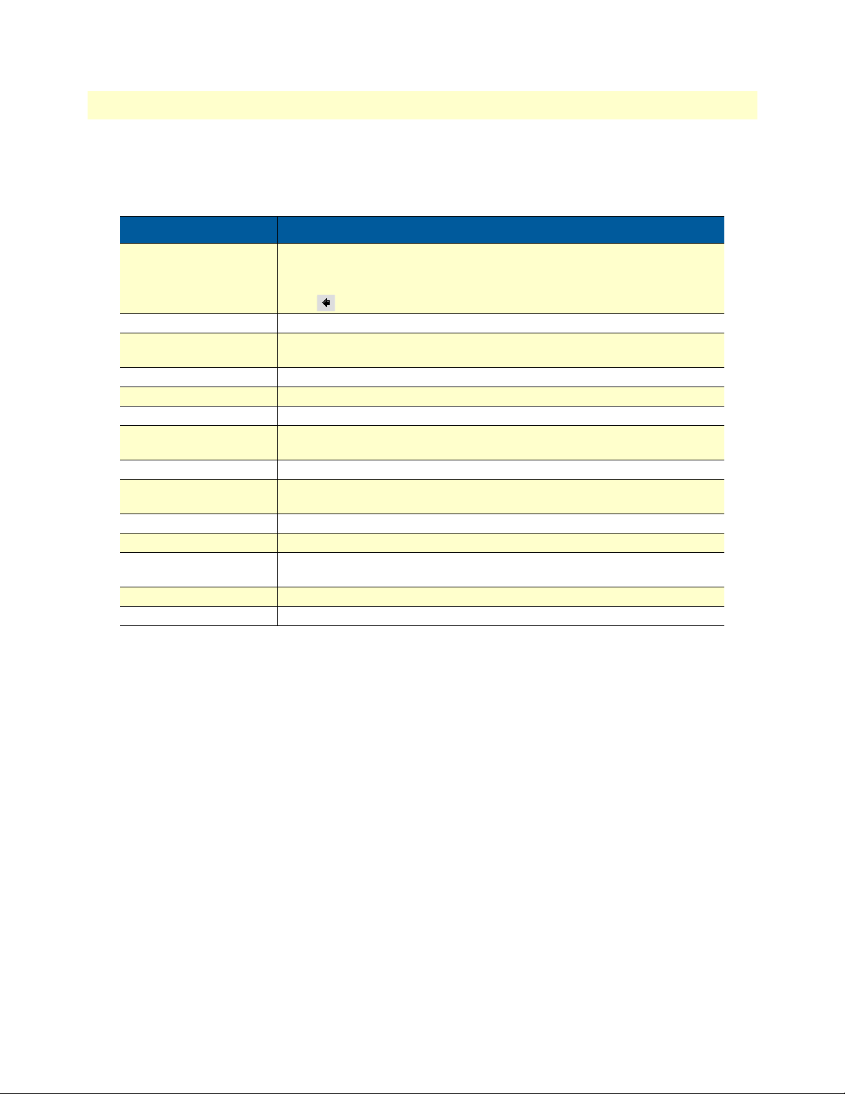
The procedures described in this manual use the following text conventions:
Table 1. General conventions
Convention Meaning
Garamond blue type Indicates a cross-reference hyperlink that points to a figure, graphic, table, or sec-
tion heading. Clicking on the hyperlink jumps you to the reference. When you
have finished reviewing the reference, click on the Go to Previous View
button in the Adobe® Acrobat® Reader toolbar to return to your starting point.
Futura bold type Commands and keywords are in boldface font.
Futura bold-italic type Parts of commands, which are related to elements already named by the user,
are in boldface italic font.
Italicized Futura type Variables for which you supply values are in italic font
Futura type Indicates the names of fields or windows.
Garamond bold type Indicates the names of command buttons that execute an action.
< > Angle brackets indicate function and keyboard keys, such as <SHIFT>, <CTRL>,
<C>, and so on.
[ ] Elements in square brackets are optional.
{a | b | c} Alternative but required keywords are grouped in braces ({ }) and are separated
by vertical bars ( | )
blue screen Information you enter is in blue screen font.
screen Terminal sessions and information the system displays are in screen font.
node The leading IP address or nodename of a SmartNode is substituted with node in
boldface italic font.
SN The leading SN on a command line represents the nodename of the SmartNode
# An hash sign at the beginning of a line indicates a comment line.
15
Page 16

Chapter 1 General information
Chapter contents
SmartNode Model 4830 DSL Series Overview...................................................................................................15
Rear Panel ......................................................................................................................................................16
Port Descriptions ......................................................................................................................................17
Reset button behavior ..............................................................................................................................17
Model Versions ........................................................................................................................................18
Front Panel .....................................................................................................................................................19
16
Page 17
SmartNode 4830 DSL Series User Manual 1 • General information
SmartNode Model 4830 DSL Series Overview
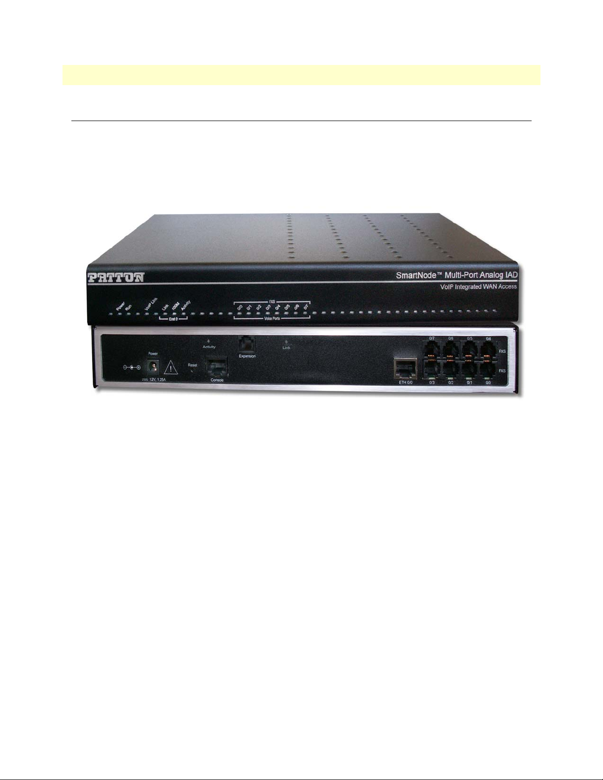
The SmartNode 4830 DSL Series Analog VoIP Integrated Access Devices combines IP routing, VPN/Security,
and Quality of Service with integrated WAN access for up to 8 voice and FAX calls over any IP or PSTN network. Leverage low-cost IP services with packet-voice and WAN connectivity for complete branch-office voiceand-data networking.
Figure 1. SmartNode 4838 with DSL shown
The SmartNode 4830 DSL Series Analog VoIP Integrated Access Devices comes equipped with one
10/100Base-T Ethernet port and an integrated ADSL or G.SHDSL port to provide voice-over-IP (VoIP) and
Internet telephony integrated with routed WAN access. The SN4830 IAD series supports Frame-Relay and
PPP networking with VPN and firewall functions, and provides extensive Quality of Service (QoS) features for
best- possible voice quality over any broadband IP network.
The SmartNode VoIP IAD performs the following major functions:
• Voice over IP and local switching via a combination of 2 to 8 analog phone ports (FXS) and 2 to 4 ana-
log line ports (FXO).
• Standa rds-compliant conversion between analog voice and digital VoIP in accordance with SIP and
H.323 protocols.
• Internet access and IP Routing with IP Quality of Service (QoS) support for mixed voice and data traf-
fic.
• Routed LAN-to-WAN connectivity between the 10/100 Ethernet LAN port and an ADSL or G.SHDSL
interface.
SmartNode Model 4830 DSL Series Overview 17
Page 18
SmartNode 4830 DSL Series User Manual 1 • General information
Reset button
Power
DSL
RJ-45 port (2GS models)
RJ-11 port (ADSL and GS models)
Ethernet
RJ-45 port
Console
RS-232 port
FXO and/or FXS
RJ-11 ports
Rear Panel
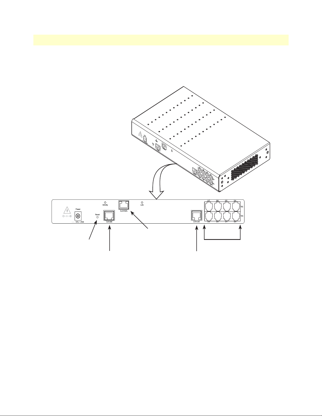
figure 2 shows one version of the SN4830 DSL series rear panel. Available with various combinations of FXS
and FXO ports, this compact analog VoIP and WAN Integrated Access Device supports 2, 4, 6, or 8 VoIP calls.
Figure 2. SmartNode 4830 DSL Series connectors
Each model within the SN4830 DSL Series comes equipped with one 10/100Base-T Ethernet port and an
integrated ADSL or G.SHDSL port. The following base model numbers are available:
• SmartNode 4832 (2 VoIP calls)
• SmartNode 4834 (4 VoIP calls)
• SmartNode 4836 (6 VoIP calls)
• SmartNode 4838 (8 VoIP calls)
SmartNode Model 4830 DSL Series Overview 18
Page 19
SmartNode 4830 DSL Series User Manual 1 • General information
Port Descriptions
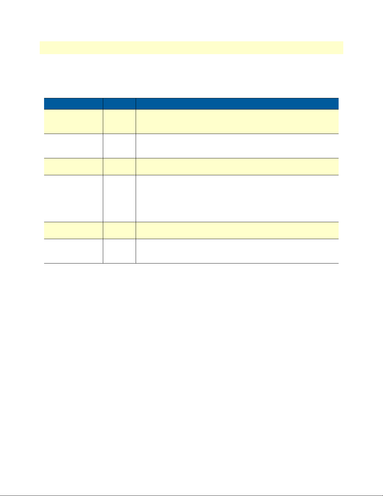
The SmartNode 4830 DSL Series rear-panel ports are described in table 2.
Table 2. Rear panel ports
Port Location Description
10/100 Ethernet
ETH 0/0
Rear panel RJ-45 connector that connects the SmartNode to an Ethernet device (e.g., a
cable or DSL modem, LAN hub or switch).
Analog voice port,
FXS
Analog voice port,
FXO
G.SHDSL or ADSL
port
Power Rear panel The gateway is available in a DC or AC power input version, labeled 10 0–
Console Front
Rear panel FXS RJ-11(6 position, 4 wire) connectors that connect the product with
an analog terminal (a telephone, for example) FXO port. EuroPOTS support (ETSI EG201 188).
Rear panel FXO RJ-11(6 position, 4 wire) connectors that connect the product with
an analog line (FXS port). EuroPOTS support (ETSI EG201 188).
Rear panel Provides up to 11.4 Mbps (G.SHDSL) or 24 Mbps (ADSL) throughput,
supporting ATM QoS. Supports multiple PVC and DSLAM interoperability.
The DSL LEDs are located on either side of the DSL port. ACT (when lit
or blinking) shows Activity, and LINK (when lit) shows that the DSL port is
connected.
240 VAC, 50/60 Hz, 200 mA
Used for service and maintenance, the Console port, an RS-232 RJ-45 con-
panel
nector, connects the product to a serial terminal such as a PC or ASCII terminal (also called a dumb terminal).
Reset button behavior
For those SmartNode devices that have a Reset button on the rear panel, its behavior is as follows:
• To restart the unit with the current startup configuration—Press for less than 1 second and release the
Reset button. The SmartNode will restart with the current startup configuration.
• To restart the unit with factory default configuration—Press the Reset button for 5 seconds until the
Power LED starts blinking. The unit will restart with factory default configuration.
• To restart the unit in bootloader mode (to be used only by trained SmartNode technicians)—Start with
the unit powered off. Press and hold the Reset button while applying power to the unit. Release the
Reset button when the Power LED starts blinking so the unit will enter bootloader mode.
SmartNode Model 4830 DSL Series Overview 19
Page 20
SmartNode 4830 DSL Series User Manual 1 • General information
Power
Model Versions
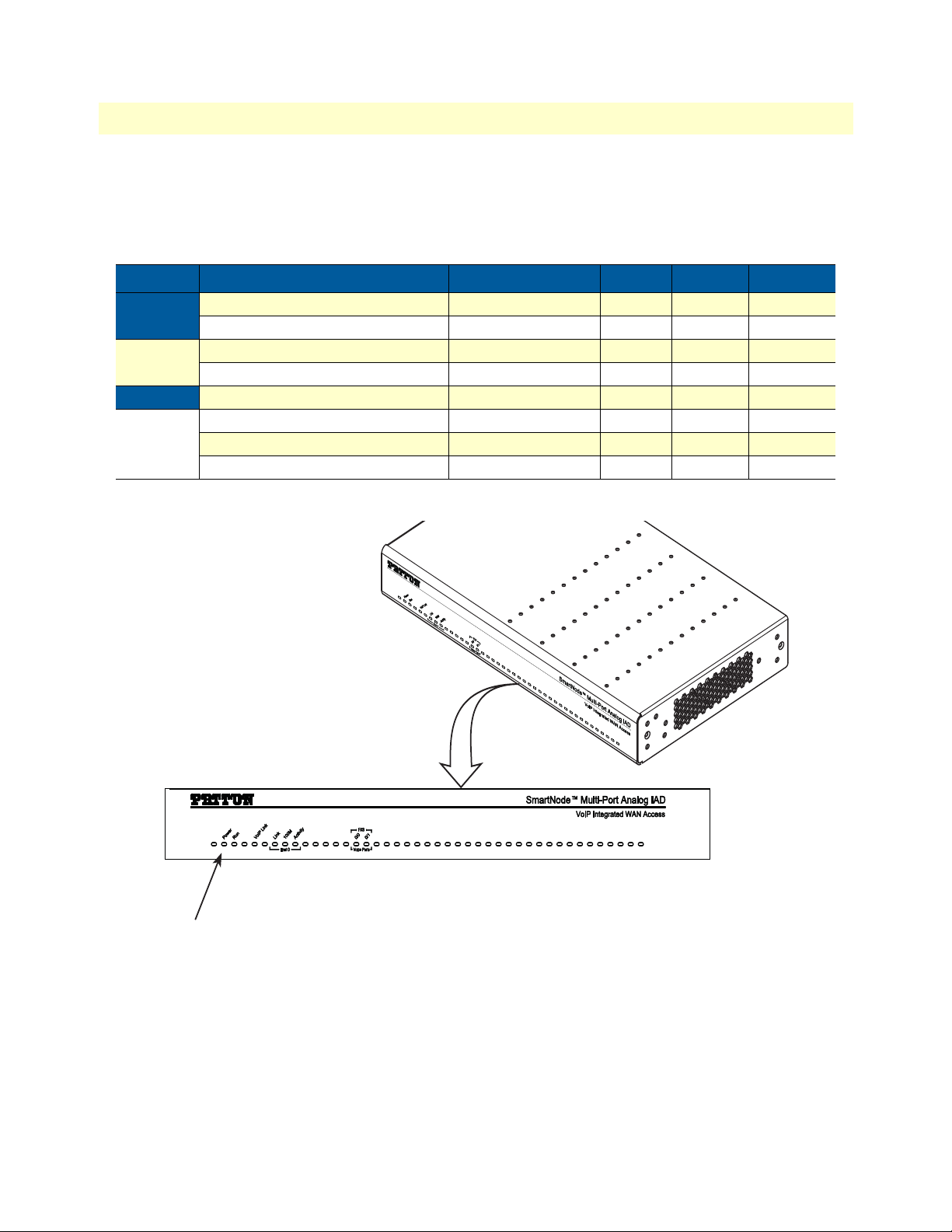
A model-code extension indicates the combination of ports the SN4830 provides; table 3 describes the available model versions in the SN4830 DSL Series.
Table 3. SmartNode 4830 DSL Series Model Codes
Model Code DSL Type FXS (JS) FXO (JO) Voice Calls
SN4832
SN4834
SN4836
SN4832/JS2GS/EUI G.SHDSL 2 0 2
SN4832/JSA/EUI ADSL 2 0 2
SN4834/JS2GS/EUI G.SHDSL 4 0 4
SN4834/JSA/EUI ADSL 4 0 4
SN4836/JS2GS/EUI G.SHDSL 6 0 6
SN4838/4JS4JOA/EUI ADSL 4 4 8
SN4838
SN4838/JS2GS/EUI G.SHDSL 8 0 8
SN4838/JSA/EUI ADSL 8 0 8
Front Panel
Figure 3. SmartNode 4830 DSL Series front panel
SmartNode Model 4830 DSL Series Overview 20
Page 21
SmartNode 4830 DSL Series User Manual 1 • General information
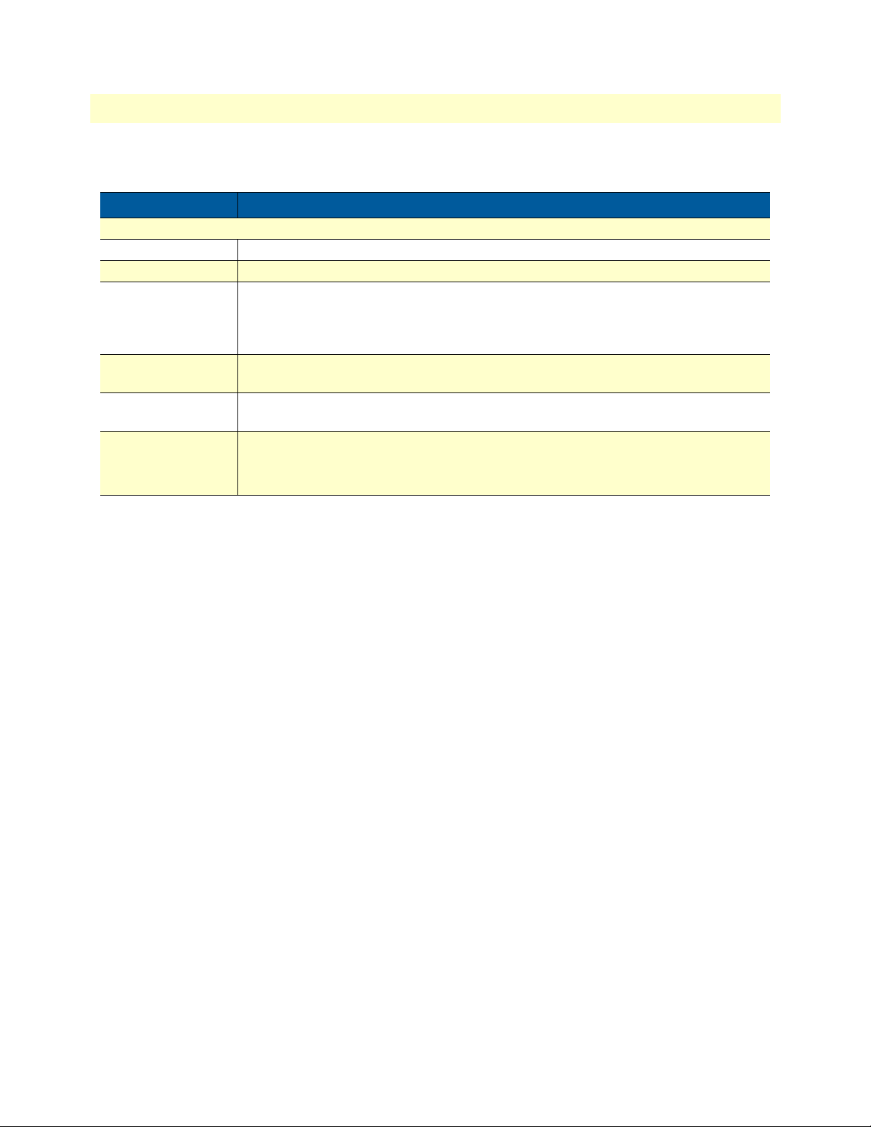
Table 4. SmartNode LED Indications
LED Description
Note If an error occurs, all LEDs will flash once per second.
Power When lit, indicates power is applied. Off indicates no power applied.
Run When lit, indicates normal operation. Flashes once per second during boot (startup).
VoIP Link When lit, indicates the gateway is registered on a gatekeeper, media gateway con-
troller, associated to a remote unit, or has an active VoIP connection. Off indicates
the unit is not configured or registered and has no active VoIP connection. Flashing
green indicates that the unit is attempting or has failed to associate/register
FXS (each port) Off indicates on-hook condition. Solid green when off-hook. Flashes to follow
ring cadence.
FXO (each port) Off indicates on-hook condition. Solid green when off-hook. Flashes to follow
ring cadence.
Ethernet • Link: Lit when Ethernet link is up.
• 100M: On when 100-Mbps Et hernet is selected.
• Activity: Flashes when data is received or transmitted from the unit to the LAN.
SmartNode Model 4830 DSL Series Overview 21
Page 22

Chapter 2 Hardware installation
Chapter contents
Planning the installation.......................................................................................................................................21
Installation checklist ......................................................................................................................................22
Site log ...........................................................................................................................................................23
Network information .....................................................................................................................................23
Network Diagram .....................................................................................................................................23
IP related information ....................................................................................................................................23
Software tools ................................................................................................................................................23
Power source ..................................................................................................................................................24
Location and mounting requirements ............................................................................................................24
Installing the VoIP IAD.......................................................................................................................................24
Mounting the VoIP IAD ................................................................................................................................24
Connecting cables ..........................................................................................................................................24
Installing an interface cable on the VoIP IAD’s FXS and FXO interface ports ......................................25
Installing the Ethernet cable .....................................................................................................................27
Installing the DSL cable ...........................................................................................................................28
Connecting to external power source .......................................................................................................29
22
Page 23

SmartNode 4830 DSL Series User Manual 2 • Hardware installation
WARNING
Planning the installation
Before you start the actual installation, we strongly recommend that you gather all the information you will
need to install and setup the device. See table 5 for an example of what pre-installment checks you might need
to carry out. Completing the pre-installation checks enables you to install and set up your VoIP IAD within an
existing network infrastructure with confidence.
Mains Voltage: Do not open the case when the power cord is connected. For systems without a power switch, line voltages are
present within the power supply when the power cord is connected. The mains outlet that is utilized to power the SmartNode
router shall be within 10 feet (3 meters) of the device, shall be easily accessible, and protected by a circu it breaker.
Note When setting up your VoIP IAD you must consider cable-length
limitation s, and potential electromagnetic int erference (EMI) as
defined by the applicable local and international regulations.
Ensure that your site is properly prepared before beginning installation.
Before installing the VoIP IAD device, the following tasks should be completed:
• Create a network diagram (see section “Network information” on page 25)
• Gather IP related information (see section “IP related information” on page 25 for more information)
• Install the hardwar e and s oftwar e needed t o configur e t he SmartNod e. (See section “Software tools”
on page 25)
• Verify power source reliability (see section “Power source” on page 26).
When you finish preparing for your VoIP IAD installation, go to section “Installing the VoIP IAD” on page 26
to install the device.
Planning the installation 23
Page 24
SmartNode 4830 DSL Series User Manual 2 • Hardware installation
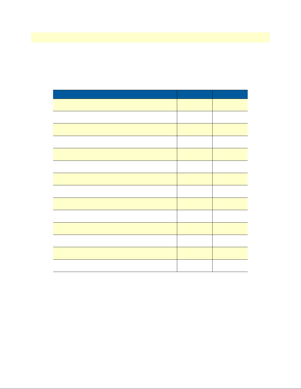
Installation checklist
The installation checklist (see table 5) lists the tasks for installing a SmartNode 4830 DSL Series VoIP IAD.
Make a copy of this checklist and mark the entries as you complete each task. For each SmartNode 4830 DSL
Series VoIP IAD, include a copy of the completed checklist in your site log.
Table 5. Installation checklist
Task Verified by Date
Network information available & recorded in site log
Environmental specifications verified
Site power voltages verified
Installation site pre-power check completed
Required tools available
Additional equipment available
All printed documents available
SmartWare release & build number verified
Rack, desktop, or wall mounting of chassis completed
Initial electrical connections established
ASCII terminal attached to console port
Cable length limits verified
Initial configuration performed
Initial operation verified
Planning the installation 24
Page 25
SmartNode 4830 DSL Series User Manual 2 • Hardware installation
Site log
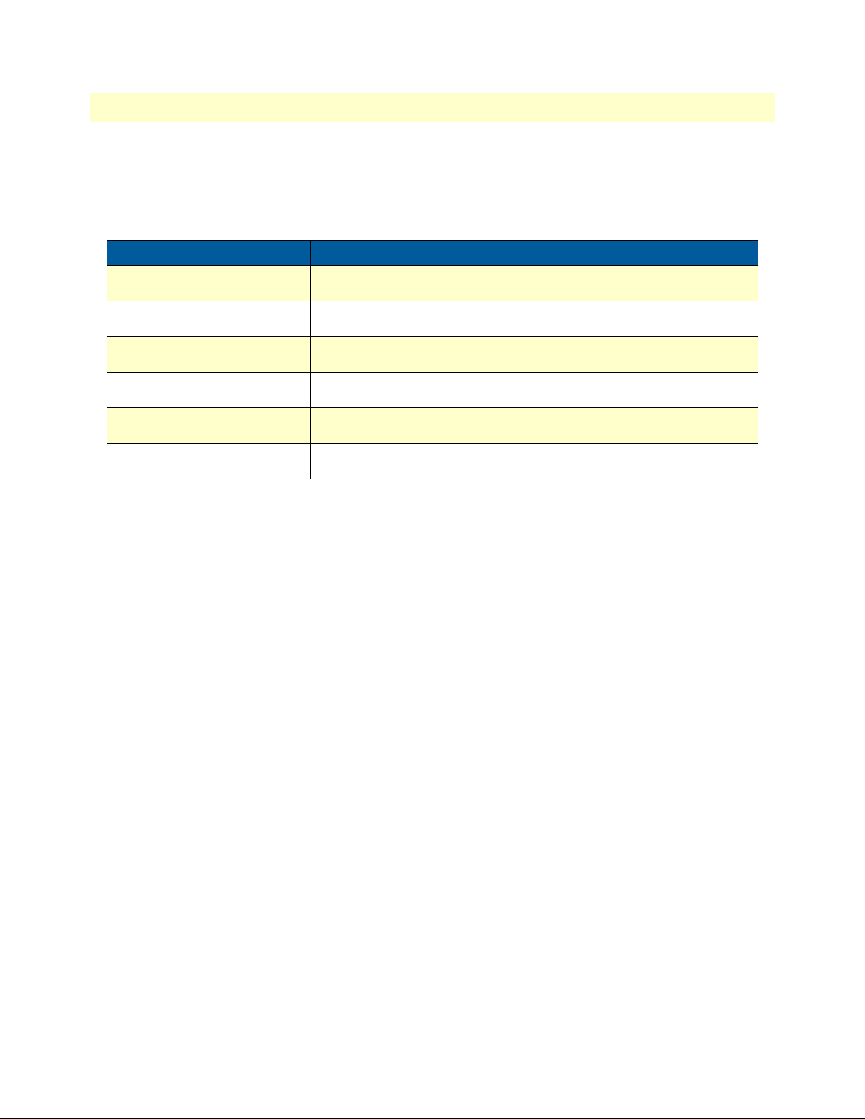
Patton recommends that you maintain a site log to record all actions relevant to the system, if you do not
already keep such a log. Site log entries should include information such as listed in table 6.
Table 6. Sample site log entries
Entry Description
Installation Make a copy of the installation checklist and insert it into the site log
Upgrades and maintenance Use the site log to record ongoing maintenance and expansion history
Configuration changes Record all changes and the reasons for them
Maintenance Schedules, requirements, and procedures performed
Comments Notes, and problems
Software Changes and updates to SmartWare software
Network information
When planning your installation there are certain network-connection considerations that you should take into
account. The following sections describe such considerations for several types of network interfaces.
Network Diagram
Draw a network overview diagram that displays all neighboring IP nodes, connected elements and telephony
components.
IP related information
Before you can set up the basic IP connectivity for your SmartNode 4830 DSL Series you should have the following information:
• IP address used for Ethernet port
• Subnet mask used for Ethernet port
• Frame Relay PVC DLCI or PPP parameters
• IP addresses used for the DSL port
• Subnet mask used for the DSL port
• IP addresses of central H.323 Gatekeeper (if used)
• IP addresses of central PSTN Gateway for H.323 and/or ISoIP based calls
• IP addresses of central TFTP Server used for configurat ion upload and download
Software tools
You will need a PC (or equivalent) with a VT-100 emulation program (e.g. HyperTerminal) to configure the
software on your SmartNode VoIP IAD.
Planning the installation 25
Page 26
SmartNode 4830 DSL Series User Manual 2 • Hardware installation
WARNING
CAUTION
Power source
If you suspect that your AC power is not reliable, for example if room lights flicker often or there is machinery
with large motors nearby, have a qualified professional test the power. Install a power conditioner if necessary.
Location and mounting requirements
The SmartNode VoIP IAD is intended to be placed on a desktop or similar sturdy, flat surface that offers easy
access to the cables. Allow sufficient space at the rear of the chassis for cable connections. Additionally, you
should consider the need to access the unit for future upgrades and maintenance.
Installing the VoIP IAD
SmartNode VoIP IAD installation consists of the following:
• Placing the device at the de sired ins tallat ion loca tion ( see secti on “Mounting the VoIP IAD” on page 26)
• Installing the interface and power cables (see section “Connecting cables” on page 26)
When you finish installing the SmartNode, go to chapter 3, “Getting started with the SmartNode” on page 32.
Mounting the VoIP IAD
Place the VoIP IAD on a desktop or similar sturdy, flat surface that offers easy access to the cables. The VoIP
IAD should be installed in a dry environment with sufficient space to allow air circulation for cooling.
Note For proper ventilation, leave at least 2 inches (5 cm) to the left,
right, front, and rear of the SmartNode VoIP IAD.
Connecting cables
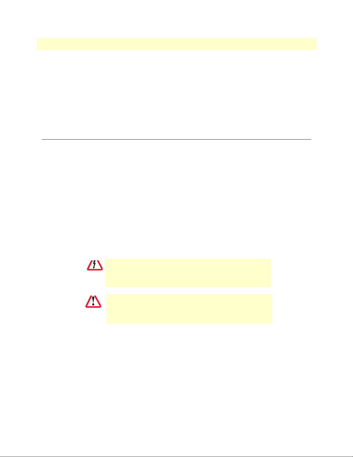
Do not work on the system or connect or disconnect cables during
periods of lightning activity.
The interconnecting cables shall be acceptable for external use and
shall be rated for the proper application with respect to voltage, current, anticipated temperature, flammability, and mechanical serviceability.
Installing VoIP IAD cables takes place in the following order:
1. Installing the RJ-11 voice port (FXS) cable or cables (see section “Installing an interface cable on the
VoIP IAD’s FXS and FXO interface ports” on page 27)
2. Installing the 10/100 Ethernet port cable (see section “Installing the Ethernet cable” on page 29)
3. Installing the DSL cable (see section “Installing the DSL cable” on page 30)
4. Installing the power input (see section “Connecting to external power source” on page 31)
Installing the VoIP IAD 26
Page 27
SmartNode 4830 DSL Series User Manual 2 • Hardware installation
Phone
Ring (-) 3
Tip (+) 4
3 Ring (-)
4 Tip (+)
RJ-11, male RJ-11, male
Installing an interface cable on the VoIP IAD’s FXS and FXO interface ports
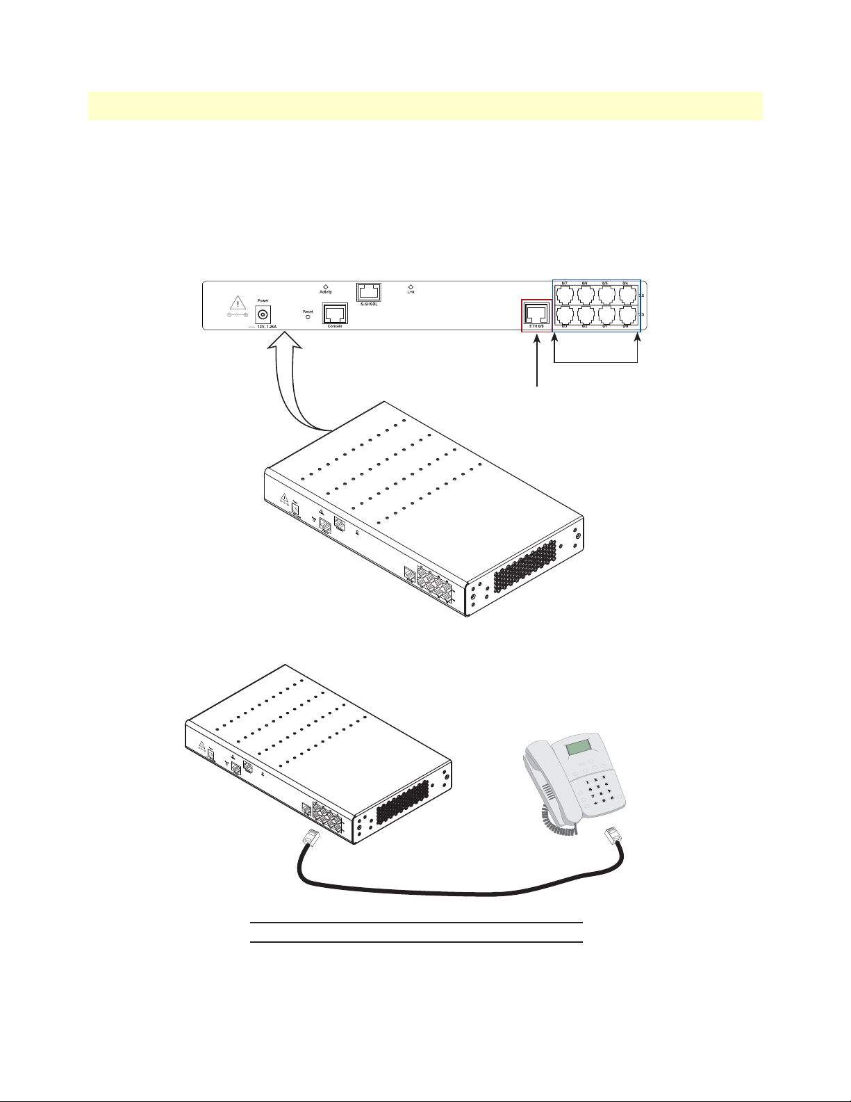
The gateway comes with at least two FXS or FXO analog ports—or a combination of FXS and FXO ports—
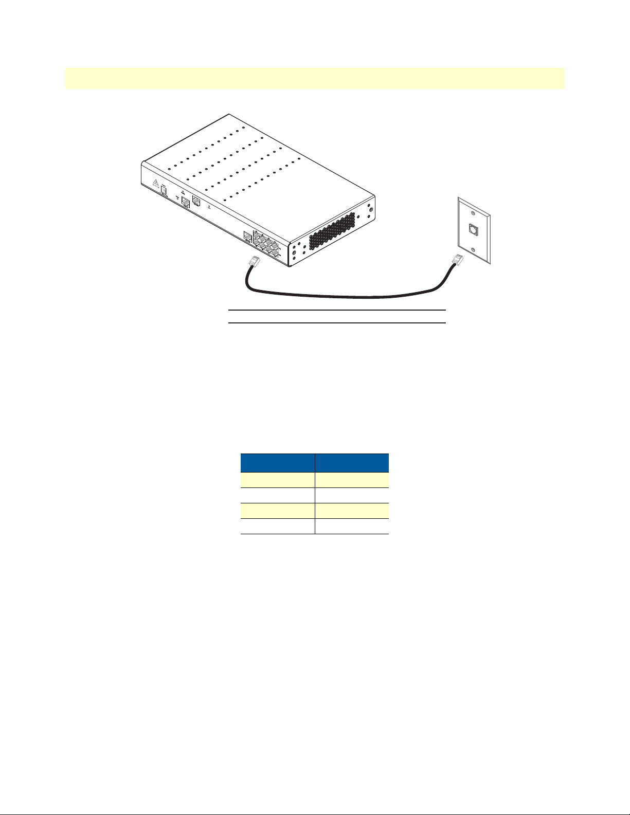
located on the back of the VoIP IAD (see figure 4). The FXS interfaces are connected to analog devices via cables
(see figure 5) terminated with RJ-11 connectors (see figure 6 and table 7 on page 28 for pin-out information).
The FXO interface connects the VoIP IAD with analog lines via cables (see figure 7 on page 29) terminated with
RJ-11 connectors (see figure 6 and table 7 on page 28 for pin-out information).
Analog ports (FXS)
Ethernet
connector
Figure 4. Rear view showing location of Ethernet and FXS connectors (SmartNode 4838 shown)
Figure 5. Analog FXS connection
Installing the VoIP IAD 27
Page 28
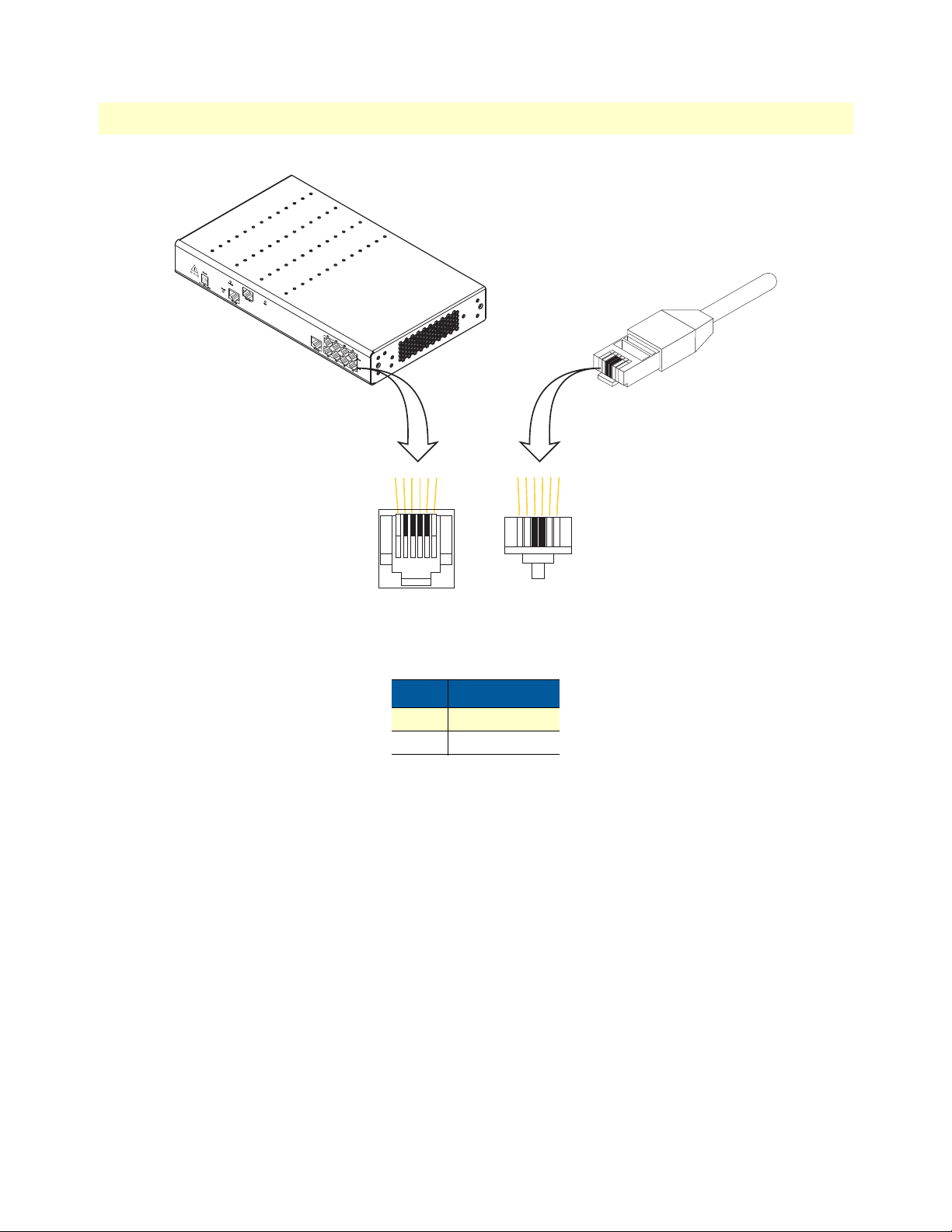
SmartNode 4830 DSL Series User Manual 2 • Hardware installation
654321
Socket
123456
Plug
Figure 6. RJ-11 pinout diagram
Table 7. RJ-11 socket
Pin Signal
3 Ring (-)
4 Tip (+)
Installing the VoIP IAD 28
Page 29
SmartNode 4830 DSL Series User Manual 2 • Hardware installation
PSTN
wall plate
RJ-11, male RJ-11, male
Ring (-) 3
Tip (+) 4
3 Ring (-)
4 Tip (+)
Figure 7. Analog FXO connection
Installing the Ethernet cable
The SmartNode 4830 DSL Series has automatic MDX (auto-cross-over) detection and configuration on the
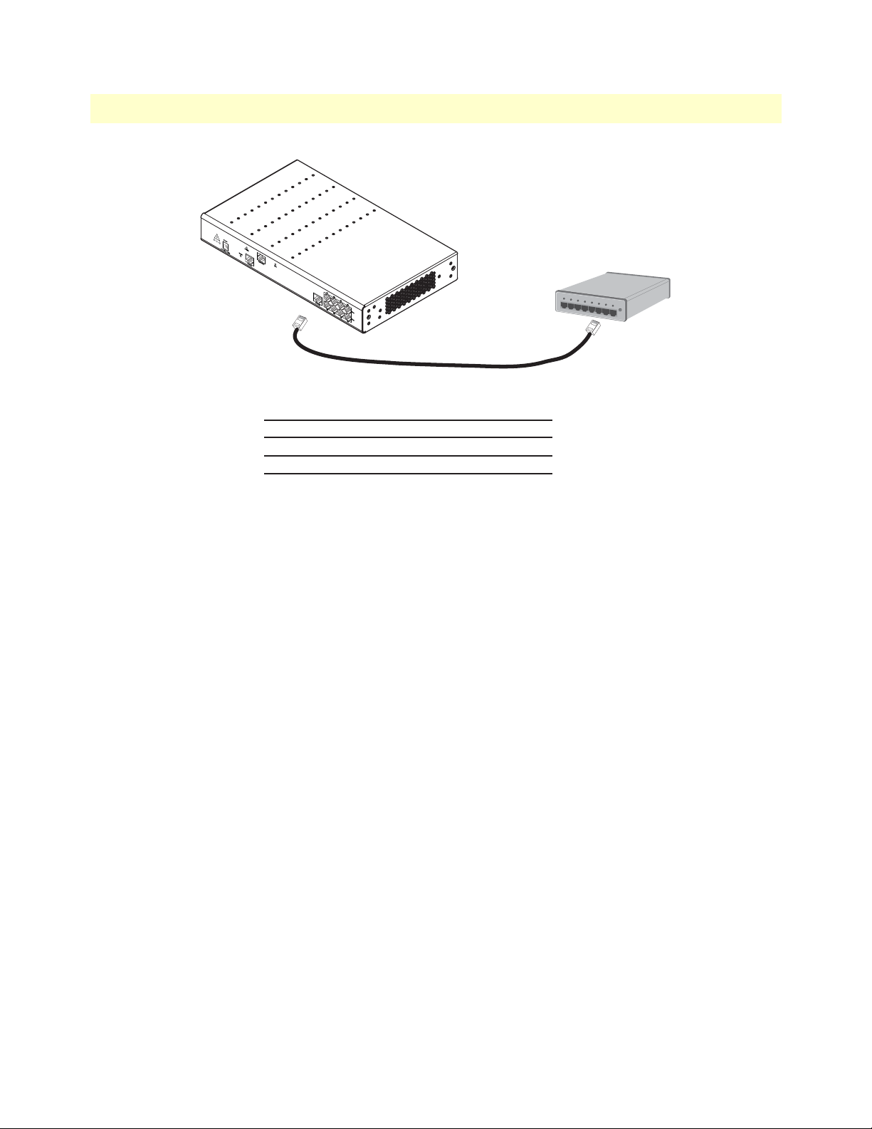
Ethernet port. The Ethernet port can be connected to a host or hub/switch with a straight-through wired cable
(see figure 8). Ethernet devices (10Base-T or 100Base-T) are connected to the SmartNode’s Ethernet port (see
table 8 for port pin-out listing) via a cable terminated with an RJ-45 plug.
Table 8. Ethernet 10/100Base-T (RJ-45) port pin-outs
Pin Signal
1 TX+
2 TX-
3 RX+
6 RX-
Note Pins not listed are not used.
Installing the VoIP IAD 29
Page 30
SmartNode 4830 DSL Series User Manual 2 • Hardware installation
Hub
Straight-through cable
SmartNode: RJ-45, male
Tx+
1
Tx-
2
Rx+
3
Rx-
6
Hub/switch: RJ-45, male
1 Rx+
2 Rx3 Tx+
6 Tx-
Figure 8. Connecting a SmartNode 4830 DSL Series device to a hub
Installing the DSL cable
The SmartNode Model 4830 comes with an option for a G.SHDSL or ADSL interface. For 2GS models, use a
straight-through RJ-45 cable to connect the DSL port. For ADSL and GS models, use a straight-through RJ-11
cable to connect the DSL port. (For a list and description of SmartNode 4830 DSL series model types, refer to
table 3 on page 18).
Installing the VoIP IAD 30
Page 31
SmartNode 4830 DSL Series User Manual 2 • Hardware installation
CAUTION
Connecting to external power source
The VoIP IAD comes with an internal or external power supply. This section describes installing the power
cord into the VoIP IAD. Do the following:
Note Do not connect the power cord to the po we r out let at t his ti me .
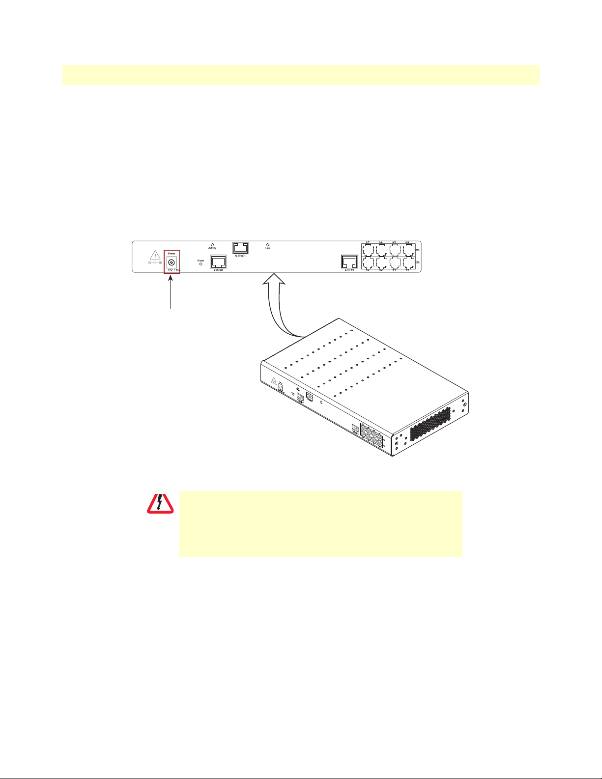
1. Insert the barrel type connector end of the AC power cord into the external power supply connector
(see figure 9).
2. Insert the female end of the power cord into the internal power supply connector (see figure 9).
Power
connector
Figure 9. Power connector location on rear panel
The VoIP IAD power supply automatically adjusts to accept an input
voltage from 100 to 240 VAC (50/60 Hz).
Verify that the proper voltage is present before plugging the power
cord into the receptacle. Failure to do so could result in equipment
damage.
3. Verify that the AC power cord included with your VoIP IAD is compatible with local standards. If it is not,
refer to chapter 5, “Contacting Patton for assistance” on page 46 to find out how to replace it with a com-
patible power cord.
4. Connect the male end of the power cord to an appropriate power outlet.
5. Verify that the green Power LED is lit (see Figure 3 on page 20).
Congratulations, you have finished installing the SmartNode VoIP IAD! Now go to chapter 3, “Getting started
with the SmartNode” on page 32.
Installing the VoIP IAD 31
Page 32

Chapter 3 Getting started with the SmartNode
Chapter contents
Introduction..........................................................................................................................................................31
1. Configure IP address........................................................................................................................................32
Power connection and default configuration .................................................................................................32
Connect with the PC’s serial interface ...........................................................................................................32
Login ..............................................................................................................................................................33
Changing the IP address ................................................................................................................................33
2. Connect the SmartNode to the network...........................................................................................................34
3. Load configuration...........................................................................................................................................34
Bootloader............................................................................................................................................................35
Start Bootloader .............................................................................................................................................35
Start-up with factory configuration ...............................................................................................................36
Load a new application image (SmartWare) via TFTP .................................................................................36
Load a new application image (SmartWare) via the serial link .....................................................................38
Additional information.........................................................................................................................................38
32
Page 33
SmartNode 4830 DSL Series User Manual 3 • Getting started with the SmartNode
Introduction
This chapter leads you through the basic steps to set up a new SmartNode and to download a configuration.
Patton SmartNodes can be used for a wide variety of IP-based network applications. To support and ease the
configuration of the SmartNodes configuration, templates for the most important applications are available on
the Patton server at www.patton.com/smartnode.
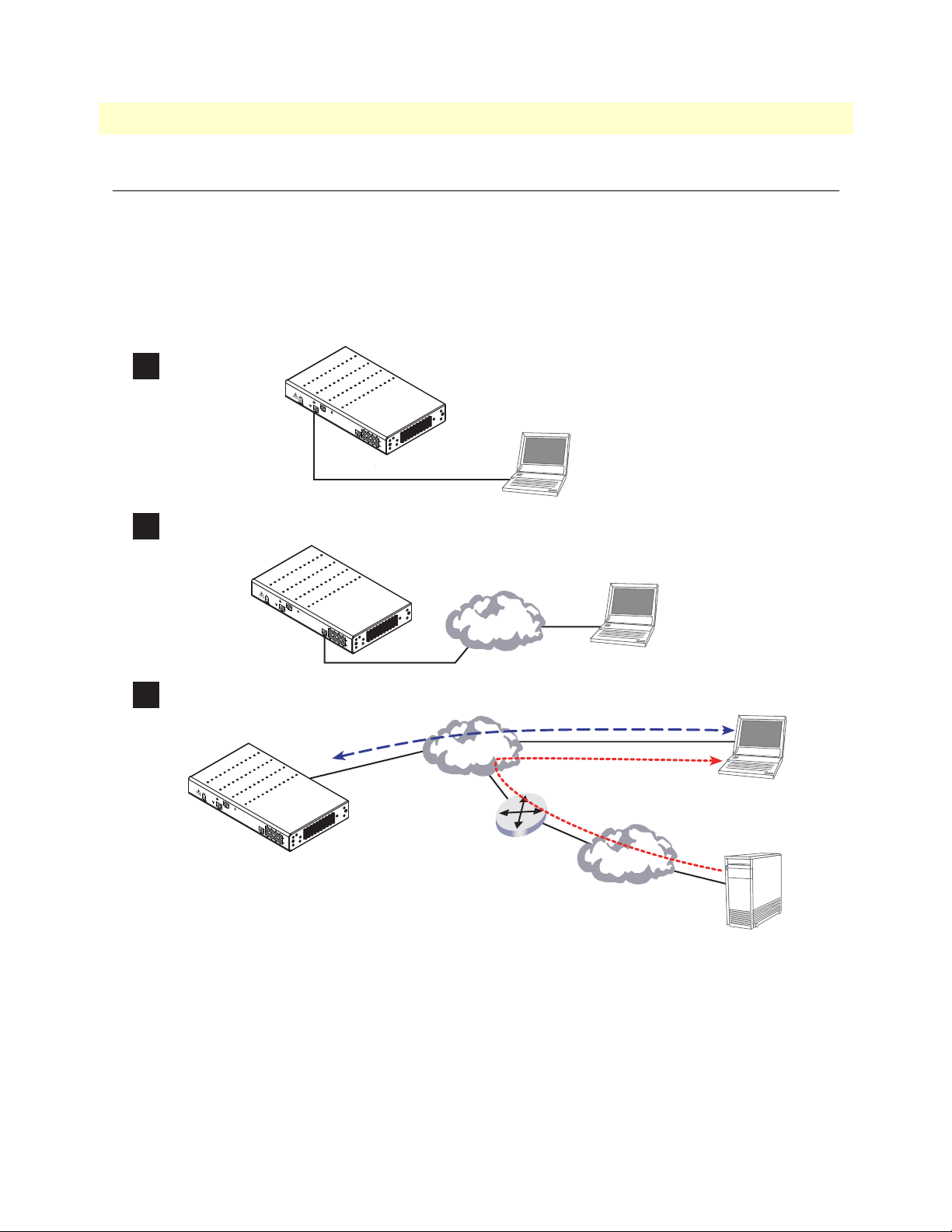
The main steps for setting up a new SmartNode are shown in figure 10.
Configure IP address
1
Console port
Connect the SmartNode to the network
2
Load configuration
3
Ethernet interface
ETH0
Serial
interface
Network
Network
PC or workstation
with VT-100
emulation terminal
Network
interface
3. Load configuration
1. Download configuration example
Internet
PC or workstation
or VT-100 emulation
terminal
2. Modify configuration
Note
You can manually configure the
SmartNode. You do not have to load a
configuration file.
Figure 10. Steps for setting up a new SmartNode
Introduction 33
Patton Web server
with configuration examples
Page 34
SmartNode 4830 DSL Series User Manual 3 • Getting started with the SmartNode
1. Configure IP address
Power connection and default configuration
The factory default configuration for the Ethernet IP addresses and network masks are listed in table 9. Both Ethernet interfaces are activated upon power-up. LAN interface ETH 0/1 (LAN) provides a default DHCP server.
Table 9. Factory default IP address and network mask configuration
IP Address Network Mask
LAN interface Ethernet 1 (ETH 0/0) 192.168.1.1 255.255.255.0
DHCP address range 192.168.1.10–192.168.1.19 255.255.255.0
The Ethernet interface is activated upon power-up.
If these addresses match with those of your network, go to section “2. Connect the SmartNode to the network”
on page 36. Otherwise, refer to the following sections to change the addresses and network masks.
Connect with the PC’s serial interface
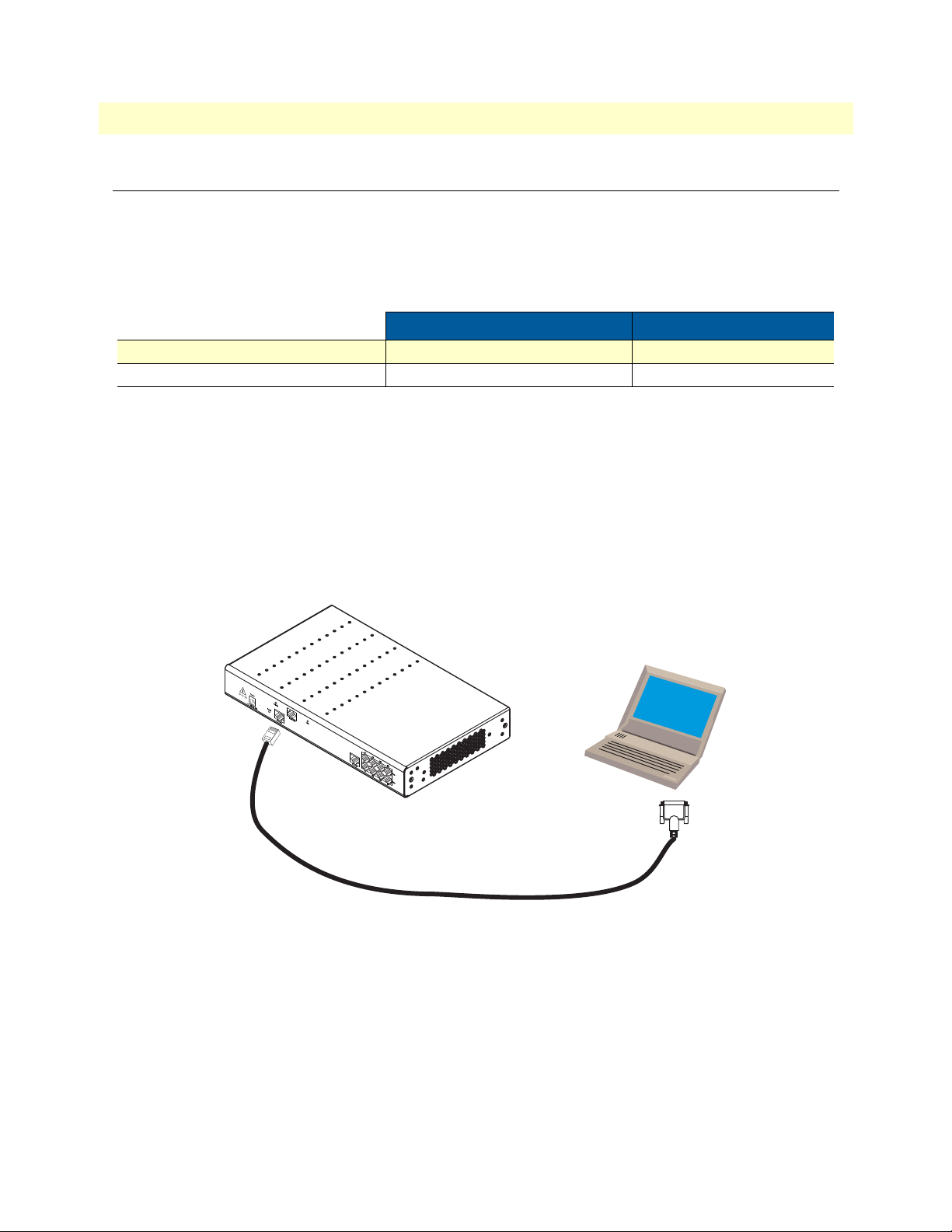
The Console port is wired as an EIA-561, RS-232 port. Use the included Model 16F-561 adapter and cable (see
figure 11) between the SmartNode’s Console port and a PC or workstation’s RS-232 serial interface. Activate the
terminal emulation program on the PC or workstation that supports the serial interface (e.g. HyperTerm).
Figure 11. Connecting to the terminal
Terminal emulation program settings:
• 9600 baud
• no parity
• 8 bit
• 1 stop bit
• No flow control
Serial Terminal
Note A Patton Model 16F-561 RJ45 to DB-9 adapter is included with
each SmartNode 4830 Series device
1. Configure IP address 34
Page 35

SmartNode 4830 DSL Series User Manual 3 • Getting started with the SmartNode
Login
Accessing your SmartNode via the local console port (or via a Telnet session) causes the login screen to display.
Type the factory default login: administrator and leave the password empty. Press the Enter key after the password prompt.
login:administrator
password: <Enter>
172.16.40.1>
After you have successfully logged in you are in the operator execution mode, indicated by > as command line
prompt. With the commands enable and configure you enter the configuration mode.
172.16.40.1>enable
172.16.40.1#configure
172.16.40.1(cfg)#
Changing the IP address
Select the context IP mode to configure an IP interface.
172.16.40.1(cfg)#context ip product
172.16.40.1(ctx-ip)[product]#
Now you can set your IP address and network mask for the interface eth0. Within this example a class C network (172.16.1.0/24) is assumed. The IP address in this example is set to 172.16.1.99 (you should set this to
an unused IP address on your network).
172.16.40.1(ctx-ip)[product]#interface eth0
172.16.40.1(if-ip)[eth0]#ipaddress 172.16.1.99 255.255.255.0
2002-10-29T00:09:40 : LOGINFO : Link down on interface eth0.
2002-10-29T00:09:40 : LOGINFO : Link up on interface eth0.
172.16.1.99(if-ip)[eth0]#
Copy this modified configuration to your new start-up configuration. Upon the next start-up the system will
initialize itself using the modified configuration.
172.16.1.99(if-ip)[eth0]#copy running-config startup-config
172.16.1.99(if-ip)[eth0]#
The SmartNode can now be connected with your network.
1. Configure IP address 35
Page 36
SmartNode 4830 DSL Series User Manual 3 • Getting started with the SmartNode
2. Connect the SmartNode to the network
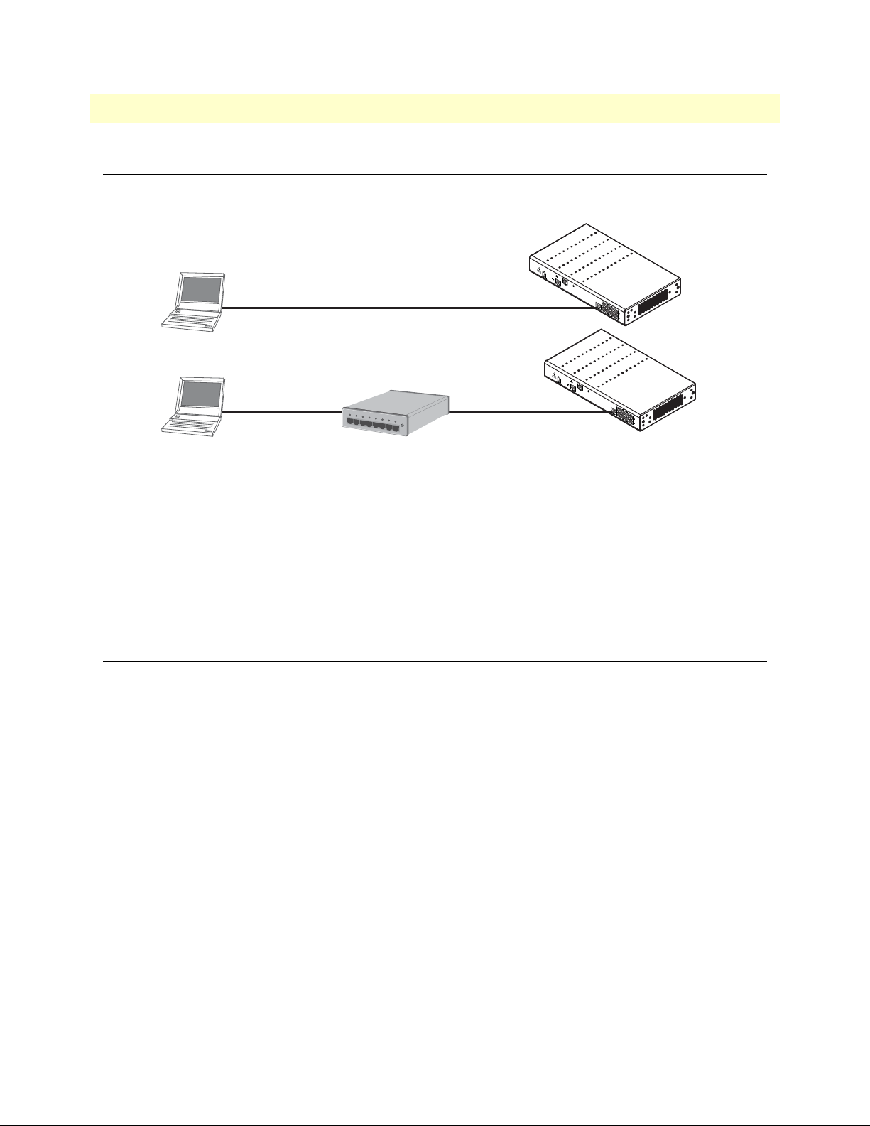
The 4830 Ethernet port is auto-MDX, therefore a straight-through wired cable can be used for host and switch
connections (see figure 12).
Network
interface ETH 0
Cross-over cable
Host
SmartNode
Hub
Straight-through
wired cable
ETH 0
SmartNode
Host
Network
interface
Straight-through
wired cable
Figure 12. Connecting the SmartNode to the network
You can check the connection with the ping command to another host on the local LAN.
172.16.1.99(if-ip)[eth0]#ping <IP Address of the host>
Respectively from the host: ping 172.16.1.99
Note T o ping outside your local LAN, you will need to configure the
default gateway.
3. Load configuration
Patton provides a collection of configuration templates on the support page at www.patton.com/smartnode—
one of which may be similar enough to your application that you can use it to speed up configuring the SmartNode. Simply download the configuration note that matches your application to your PC. Adapt the configuration as described in the configuration note to your network (remember to modify the IP address) and copy
the modified configuration to a TFTP server. The SmartNode can now load its configuration from this server.
Note If your application is unique and not covered by any of Patton’s configu-
ration templates, you can manually configure the SmartNode instead of
loading a configuration fi le template. In that case, refe r to th e SmartNode
Series SmartWare Software Configurat ion Guide for information on configuring the SmartNode device.
In this example we assume the TFTP server on the host with the IP address 172.16.1.11 and the configuration
named SN.cfg in the root directory of the TFTP server.
172.16.1.99(if-ip)[eth0]#copy tftp://172.16.1.11/SN.cfg startup-config
Download...100%
172.16.1.99(if-ip)[eth0]#
2. Connect the SmartNode to the network 36
Page 37

SmartNode 4830 DSL Series User Manual 3 • Getting started with the SmartNode
IMPORTANT
After the SmartNode has been rebooted the new startup configuration will be activated.
When you issue the reload command, the SmartNode will ask if you
want to copy the running configuration to the startup configuration.
Since you just downloaded a configuration file to the startup configuration you must answer this question with NO. Otherwise, the downloaded configuration will be overwritten and lost!
172.16.1.99(if-ip)[eth0]#reload
Running configuration has been changed.
Do you want to copy the 'running-config' to the 'startup-config'?
Press 'yes' to store, 'no' to drop changes : no
Press 'yes' to restart, 'no' to cancel : yes
The system is going down
Bootloader
The bootloader ensures that basic operations, network access, and downloads are possible in case of interrupted
or corrupted application image downloads. It offers console access to the Bootloader and the capability for
downloading application images (e.g. SmartWare) via the serial link of the console.
Start Bootloader
To start the Bootloader, power on the SmartNode while pressing the reset button. Open a Telnet session to the
SmartNode via one of the Ethernet interfaces, or open a CLI session via the console port (if available on the
SmartNode). The login display will appear. Using the credentials admin / patton , log in to the SmartNode.
The following prompt will be displayed:
RedBoot>
Ty p e help to display an overview of the available commands.
Bootloader 37
Page 38
SmartNode 4830 DSL Series User Manual 3 • Getting started with the SmartNode
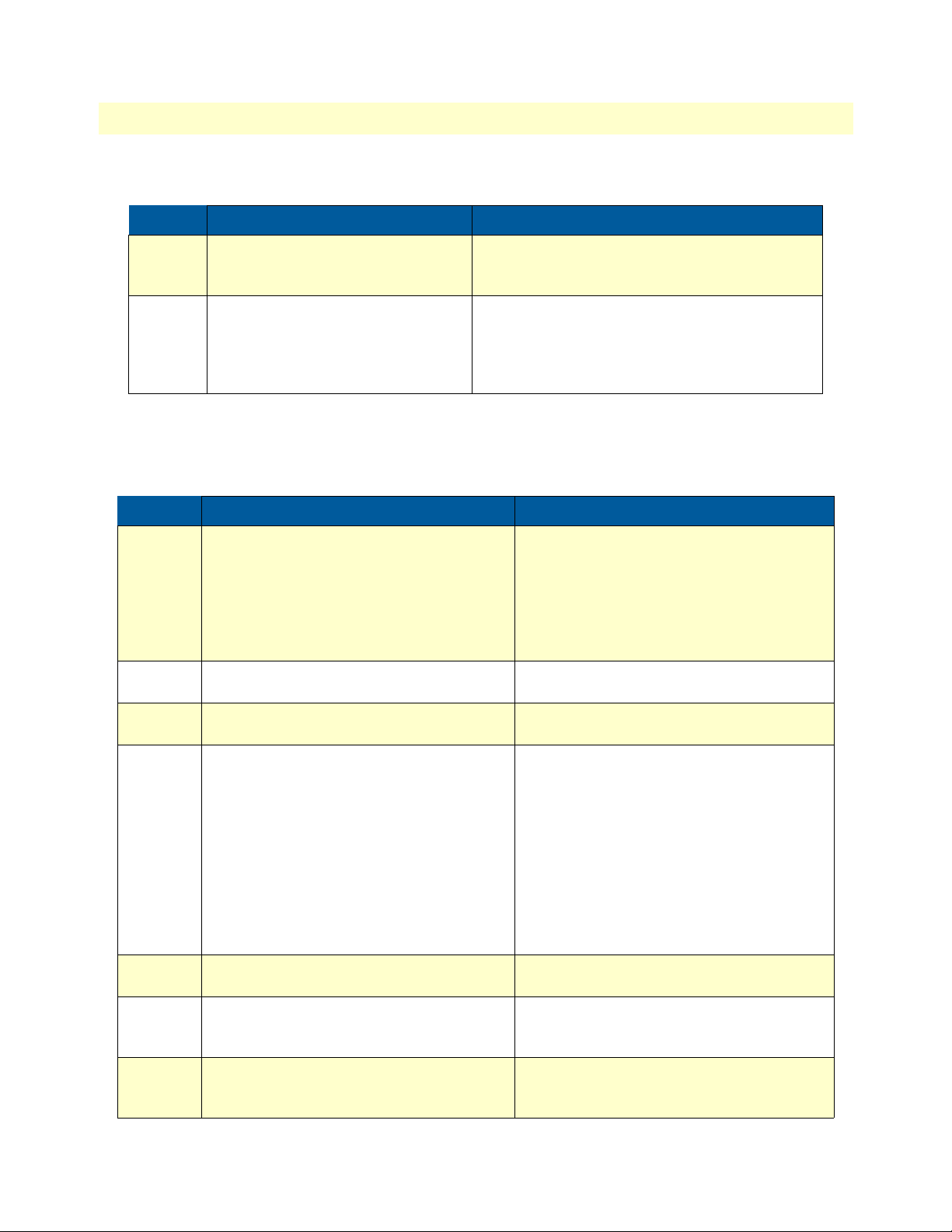
Start-up with factory configuration
Step Command Purpose
1 RedBoot> fis load Copies the SmartWare application image from the
persistent memory (flash:) to the volatile memory
(RAM) from where it will be executed.
2 RedBoot> go -s factory-config Starts the SmartWare application telling it to use
‘factory-config’ as startup configuration.
You can also start-up with any other configuration
available in the persistent memory (nvram:) by
providing its name instead of ‘factory-config’.
Load a new application image (SmartWare) via TFTP
The following procedure downloads the application image (SmartWare) for the mainboard. See the note below
on how to download the respective CLI description file.
Step Command Purpose
1
optional
2
optional
3
optional
4 RedBoot> load -r -v -h host -b
5 RedBoot> fis delete -n 1 Deletes the first application image.
6 RedBoot> fis create Stores the downloaded application image to
7 RedBoot> fis list -l Checks whether the image has been suc-
RedBoot> ip_address - l local_ip_address
[/mask_len]
RedBoot> ip_address -g gateway Sets the IP address of the default gateway.
RedBoot> ping -h tftp-server_ip_address Tests the connectivity to the TFTP server.
base_address file_name
Sets the IP address and subnet mask of the
Ethernet interface 0/0 which shall be used to
receive the new application image.
mask_len is the length of the network address
(or the number of 1’s within the subnet
mask).
See Note below.
Downloads an application image into the volatile memory (RAM) from where the SmartNode could directly execute it.
host: IP address of the TFTP server
base_address: memory location where to
store the application image. Use the default
address 0x1800100
file_name: path and name of the file on the
TFTP server. Note: use the image file that
contains the whole application, not the image
parts.
Reply with ‘y’ to the confirmation request.
the permanent memory (flash:).
Reply with ‘y’ to the confirmation request.
cessfully stored, whether it is the desired
Release and Build, and whether it is valid.
Bootloader 38
Page 39

SmartNode 4830 DSL Series User Manual 3 • Getting started with the SmartNode
Step Command Purpose
8 RedBoot> go Starts the application image that was down-
loaded into the volatile memory (RAM).
Note With the Bootloader, only the Ethernet interface 0/0 is available. The
Bootloader applies the IP address, subnet mask, and default gateway that
were last configured by the Bootloader itself or by another application
(e.g. SmartWare). If an application configured the Ethernet interface 0/0
to use DHCP, the Bootloader will al so use DHCP to learn the interface
configuration. It can receive and apply the IP address, subnet mask,
default gateway, and default (TFTP) server (transmitted as basic DHCP
information ‘Next server IP address’).
Note This procedure does not download the respective CLI description file.
Download it after starting up SmartWare with the following command:
copy tftp:/ /<tftp_server_address> / < s erver path>/ b 1 flash:
Example: Downloading and storing a new application image (SmartWare)
RedBoot> ip -l 172.16.40.98/19
RedBoot> ip -g 172.16.32.1
RedBoot> ping -h 172.16.32.100
Network PING - from 172. 16.40.98 to 172.16.32.100
..........PING - received 10 of 10 expected
RedBoot> load -r -v -h 172.16.32.100 -b 0x1800100 /Sn4xxx/image.bin
Using default protocol (TFTP)
Raw file loaded 0x01800100-0x0199ca6b, 1689964 bytes, assumed entry at 0x01800100
RedBoot> fis delete -n 1
Delete image 1 - continue (y/n)? y
... Erase from 0x60030000-0x601cc974: ..........................
RedBoot> fis create
Use address 0x01 800100, size 1684402 ? - continue (y/n)? y
... Erase from 0x60030000-0x601cb3ba: ..........................
... Program from 0x00011eec-0x00011ef4 at 0x600300 00: .
... Program from 0x01800100-0x0199b4b2 at 0x60030008: ..........................
... Program from 0x00011eec-0x00011ef4 at 0x600300 00: .
Image successfully written to flash
RedBoot> fis list -l
Id Address Length State Description
Entry Load Addr Version
-------------------------------------------------------------------1 0x60030000 1693438 valid SmartWare R2.10 BUILD28015
0x01800100 0x01800100 V2.10
RedBoot> go
Starting 'SmartWare R2.10 BUILD28015' at 0x01800100 via 0x01800100
Bootloader 39
Page 40
SmartNode 4830 DSL Series User Manual 3 • Getting started with the SmartNode
Load a new application image (SmartWare) via the serial link
The Bootloader supports the ‘X-Modem’ and ‘Y-Modem’ protocols to download application images via the
serial link of the console. Do the following to initiate the download:
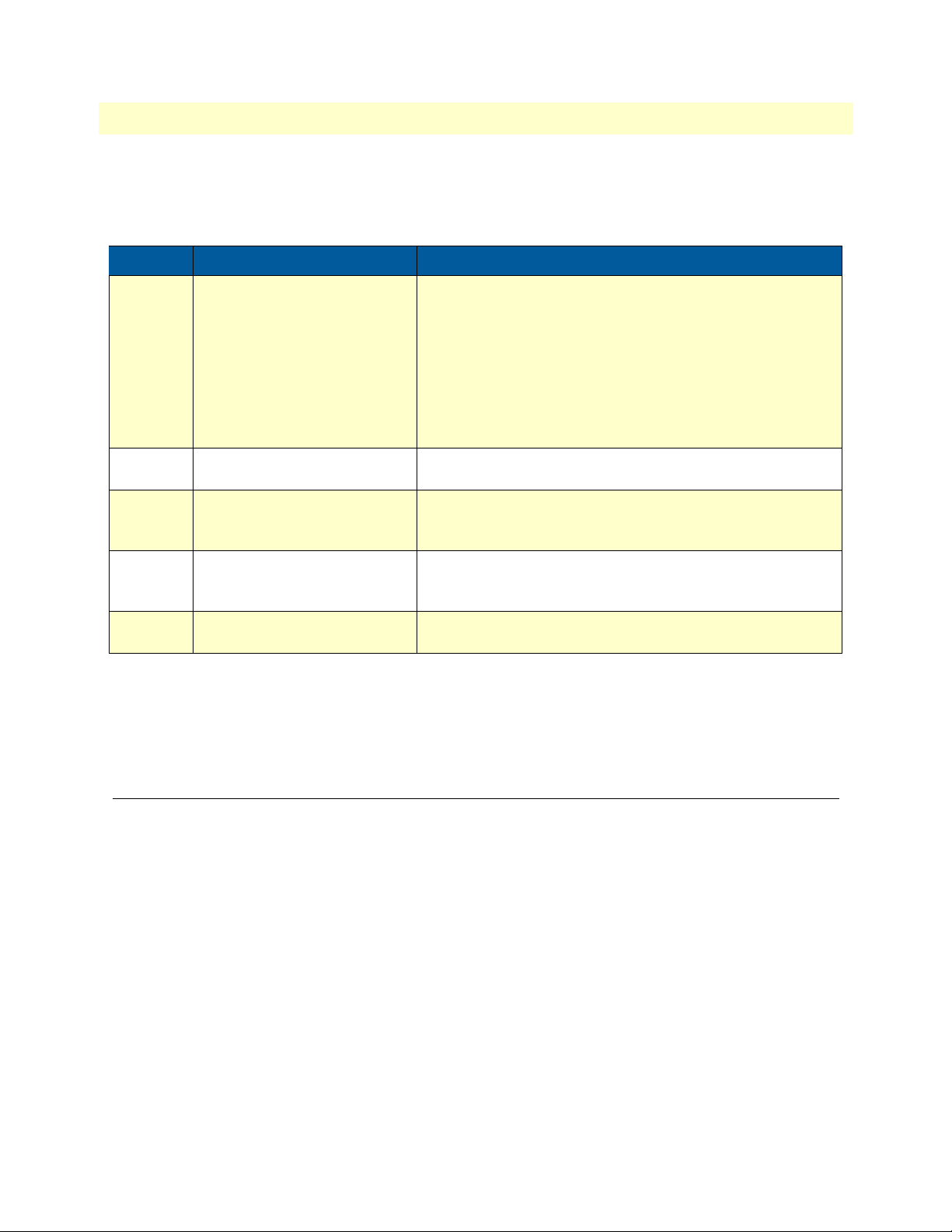
Step Command Purpose
1 RedBoot> load -r -v -m { xmo-
dem | ymodem } -b
base_address
5 RedBoot> fis delete -n 1 Deletes the first application image.
6 RedBoot> fis create Stores the downloaded application image to the permanent
7 RedBoot> fis list -l Checks whether the image has been successfully stored,
8 RedBoot> go Starts the application image that was downloaded to the vola-
Downloads an application image into the volatile memory
(RAM) from where the SmartNode could directly execute it.
‘xmodem’ or ‘ymodem’: Specify the protocol to be used, XModem or Y-Modem
base_address: memory location where to store the application image. Use the default address 0x1800100
Execute the above RedBoot command first, then start the
transfer from the terminal program with the command ‘Send
file via X-Modem’ (or similar).
Reply with ‘y’ to the confirmation request.
memory (flash:).
Reply with ‘y’ to the confirmation request.
whether it is the desired Release and Build, and whether it is
valid.
tile memory (RAM).
Note This type of download takes about 25 minutes since it use s a serial link at
only 9600 bps.
Additional information
For detailed information about configuring and operating guidance, set up procedures, and troubleshooting,
refer to the Software Configuration Guide on the Patton website at www.patton.com.
Additional information 40
Page 41

Chapter 4 DSL Basic Configuration
Chapter contents
Introduction..........................................................................................................................................................40
Line Setup ............................................................................................................................................................40
Configuring PPPoE ..............................................................................................................................................40
Configuration Summary.......................................................................................................................................41
Setting up permanent virtual circuits (PVC)........................................................................................................42
Using PVC channels in bridged Ethernet mode ............................................................................................42
Using PVC channels with PPPoE ..................................................................................................................42
Diagnostics ....................................................................................................................................................43
Troubleshooting DSL Connections......................................................................................................................43
41
Page 42
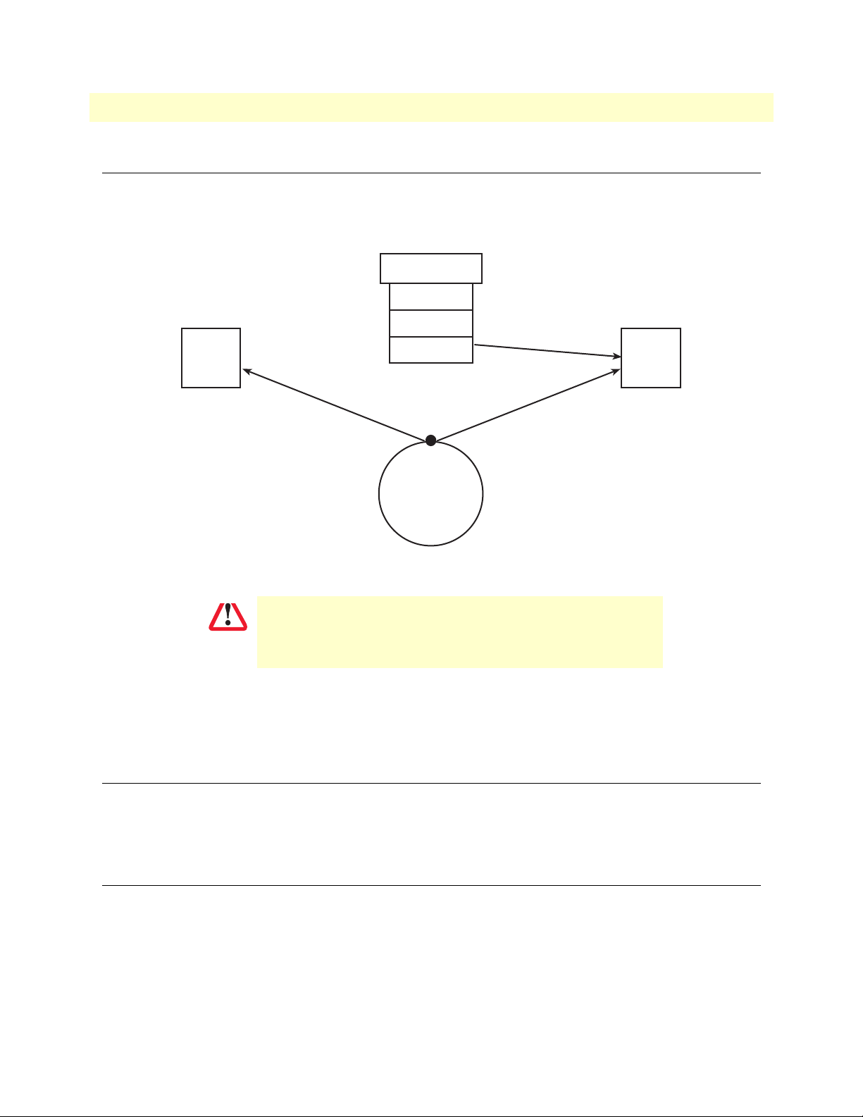
SmartNode 4830 DSL Series User Manual 4 • DSL Basic Configuration
Subscriber PPP
MySubscriber
Profile
napt
WAN
port
dsl 0 0
pvc
vpi 8 vci 35
pppoe
session MyISP
bind subscriber
MySubscriber
bind interface
WAN router
use profile napt
WAN
context
ip
WAN
interface
\ \
CAUTION
Introduction
The SN4830 model has a built-in G.SHDSL or ADSL modem. The modem appears in the configuration as
"port dsl 0 0" mode.
Figure 13. Configuring the G.SHDSL card for PPPoE
The Modem setup uses IP messages within its own subnet:
192.0.2.0/24. SmartNodes wi th built-in modems cannot use this
subnet in any other way.
Note
For information about the specifications of the G.SHDSL daughter
card,
see Appendix B, “Specifications” on page 53.
Line Setup
There is no line modulation setting. The modems automatically adapt to the bit rate and modulation used.
The status LED on the back of the device is blinking while the modem attempts to connect and lit when the
link is established. If the modem keeps blinking, check the cabling,
Configuring PPPoE
Figure 13 explains how to configure PPPoE on the SmartNode’s built-in G.SHDSL card. To configure the
DSL port for PPPoE, first you need to log in to the SmartNode via the CLI and enter configuration mode.
login: administrator
password: <enter>
SN4xxx>enable
SN4xxx>#configure
Introduction 42
Page 43

SmartNode 4830 DSL Series User Manual 4 • DSL Basic Configuration
Next, you will need to create a WAN profile, create a WAN interface, and create a subscriber. Then, you can
configure the DSL port (port dsl 0 0) for PPPoE.
Follow this example:
profile napt WAN
context ip router
interface WAN
ipaddress unnumbered
point-to-point
use profile napt WAN
tcp adjust-mss rx mtu
tcp adjust-mss tx mtu
subscriber ppp MySubscriber
dial out
authentication chap
identification outbound <username> password <password>
bind interface WAN router
port dsl 0 0
pvc vpi 8 vci 35
pppoe
session MyISP
bind subscriber MySubscriber
no shutdown
The line - use profile napt WAN - defines that the NAPT profile <profile> will be used on the ip interface
<name>. For PPPoE, you will only use outbound for identification. You will want to use authentication, which
is why you bind to a subscriber. You can use authentication chap or authentication pap. The line -
scriber MySubscriber - binds the PPPoE session to the PPP subscriber, in case authentication is required. If
you do not use authentication, then you will not have a subscriber and you will bind directly to the interface.
bind sub-
Configuration Summary
The modems offer multiple bridged Ethernet connections through logical channels within the DSL link. A logical connection is called a Permanent Virtual Circuit (PVC) and is identified by a VPI/VCI number pair. Consult your provider's configuration instructions for connections used on your DSL link. You define those PVCs
inside "port dsl 0 0":
port dsl 0 0
pvc vpi 8 vci 35
Iin the mode "pvc", you define what to do with the bridged Ethernet connection it offers:
• Bind one or more IP interfaces when your providers uses fixed ip addresses or DHCP in the network
Configuration Summary 43
Page 44
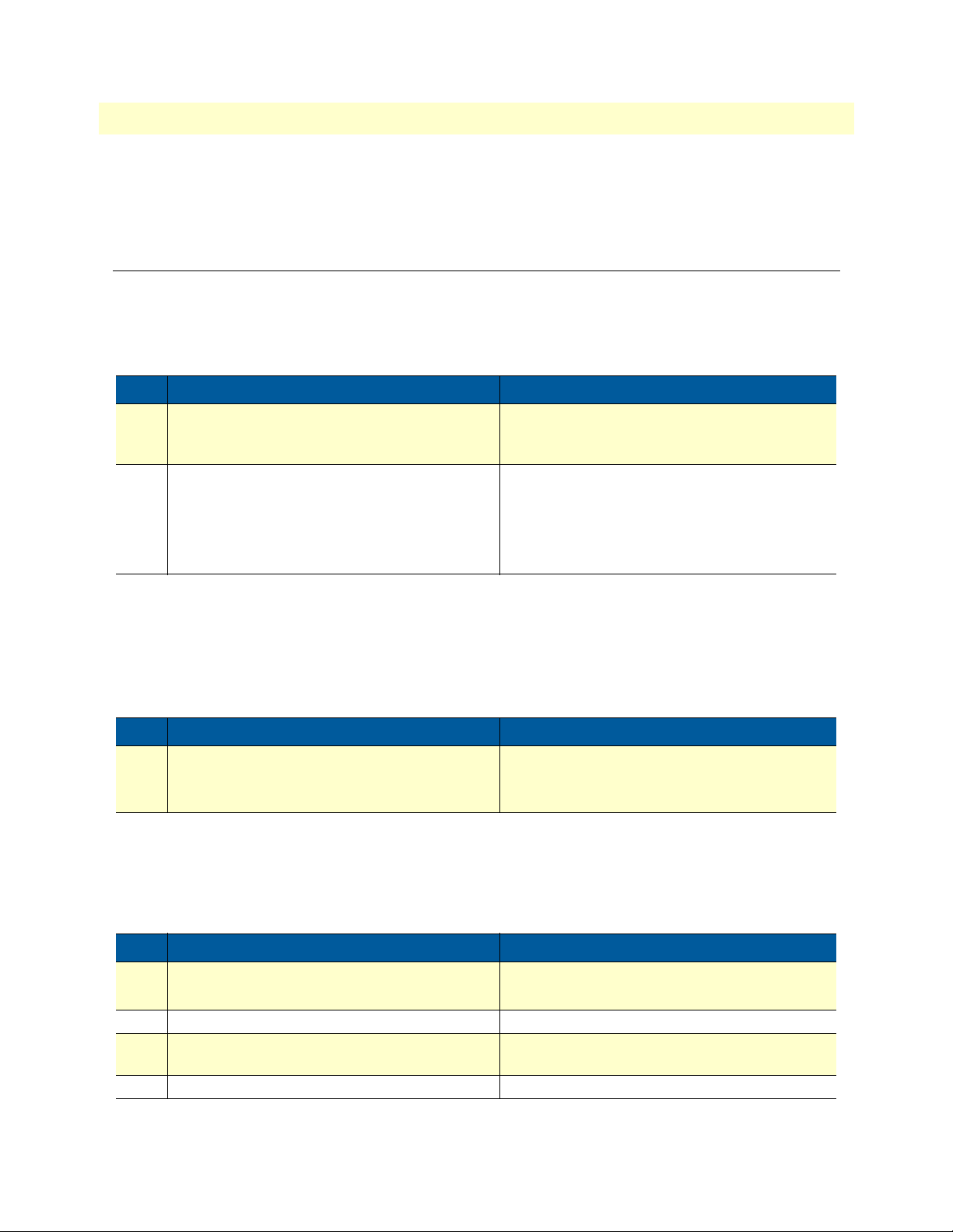
SmartNode 4830 DSL Series User Manual 4 • DSL Basic Configuration
• Enter PPPoE mode and define a PPP session if the provider is using PPPoE.
Note PPPoA is not supported.
Setting up permanent virtual circuits (PVC)
The modems currently available are using ATM to multiplex traffic over the DSL framing connection. ATM
allows you to have separate logical connections running in parallel. Those connections are called permanent
virtual circuits (PVC). All permanent virtual circuits use AAL5 framing.
Table 10. PVC Commands
Command Purpose
Step 1 node(prt-dsl)[0/0]# [no] pvc vpi 8 vci 35 Creates PVC 8/35 and enters configuration
mode for this PVC. The "no"-variant deletes the
PVC configuration.
Step 2 node(pvc)[8/35]# encapsulation {llc|vc} Sets the encapsulation to be used. Optionally
select either LLC encapsulation or VC multiplexing for this PVC.
Default: llc
Using PVC channels in bridged Ethernet mode
The PVC offers a bridged Ethernet connection as specified in RFC1483, which can be used as an IP link e.g.
with DHCP to assign the address, DNS server, and default gateway. To do this, you bind an IP interface to the
PVC like it would be done to a normal Ethernet port.
Table 11. PVC channels in bridged Ethernet mode
Command Purpose
Step 1 node(pvc)[vpi/vci]# [no] bind interface <if-
name>
Associates an IP interface configuration with this
PVC.
Using PVC channels with PPPoE
The RFC1483 bridged Ethernet connection can also be used for PPPoE. To do this, you enter PPPoE mode
within the PVC mode. All PPPoE commands apply as if the PVC was a regular Ethernet port.
Table 12. PVC channels in PPPoE mode
Command Purpose
Step 1 node(pvc)[vpi/vci]# pppoe Enters PPPoE configuration mode for this PVC.
Step 2 node(pppoe)# session <name> Defines a PPPoE session.
Step 3 node(session)[<name>]# bind subscriber
<subscriber-name>
Step 4 node(session)[<name>]# no shutdown Enables the PPPoE session
Links the session to a subscriber definition.
Setting up permanent virtual circuits (PVC) 44
Page 45
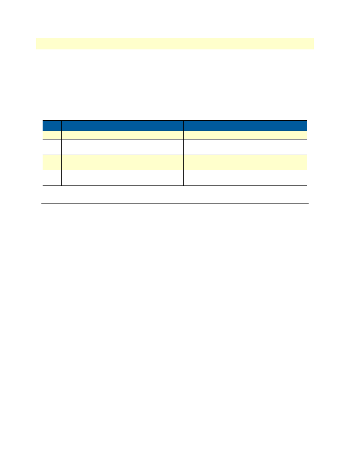
SmartNode 4830 DSL Series User Manual 4 • DSL Basic Configuration
Note The bridged PVC connectio ns a re in terna lly mapped t o VLANs on
a virtual Ethernet port 0/2 . You will therefore see references to this
third Ethernet port when displaying PPPoE status information or
debug logs.
Diagnostics
Table 13. Diagnostics commans
Command Purpose
Step 1 node> show dsl type Displays the type of modem installed.
Step 2 node> show dsl line-state Displays information about the state of the DSL
link.
Step 3 node> show dsl version Display firmware version information for the
modem.
Step 4 node# debug dsl-setup Lists the configuration interactions between the
gateway and the modem module.
Troubleshooting DSL Connections
Link State:
• Verify that the DSL link is established (status LED is continuously on)
PPPoE access:
• Check if " show pppoe det ail 3" shows " Sta te: ... . opened". This i ndicate s that th e PVC is vali d and a that
you reached a PPPoE server through it.
• Check if "show ppp networks detail 3" shows "State: .... opened" for both the "LCP" and the "CHAP"
section. If LCP is not working, there is probably no compatible authentication protocol configured.
Make sure "authentication chap" and "authentication pap" are included in the subscriber setup. If only
CHAP failed there may be an error with the username or password.
• Run the “debug” command: node# debug dsl-setup (See table 13 above).
Troubleshooting DSL Connections 45
Page 46

Chapter 5 Contacting Patton for assistance
Chapter contents
Introduction..........................................................................................................................................................45
Contact information..............................................................................................................................................45
Patton support headquarters in the USA ........................................................................................................45
Alternate Patton support for Europe, Middle East, and Africa (EMEA) .......................................................45
Warranty Service and Returned Merchandise Authorizations (RMAs)...............................................................45
Warranty coverage .........................................................................................................................................45
Out-of-warranty service ...........................................................................................................................46
Returns for credit .....................................................................................................................................46
Return for credit policy ............................................................................................................................46
RMA numbers ...............................................................................................................................................46
Shipping instructi ons ...............................................................................................................................46
46
Page 47

SmartNode 4830 DSL Series User Manual 5 • Contacting Patton for assistance
Introduction
This chapter contains the following information:
• “Contact information”—describes how to contact Patton technical support for assistance.
• “Warranty Service and Returned Merchandise Authorizations (RMAs)”—contains information about
the RAS warranty and obtaining a return merchandise authorization (RMA).
Contact information
Patton Electronics offers a wide array of free technical services. If you have questions about any of our other
products we recommend you begin your search for answers by using our technical knowledge base. Here, we
have gathered together many of the more commonly asked questions and compiled them into a searchable
database to help you quickly solve your problems:
Patton support headquarters in the USA
• Online support: Available at www.pat ton.com
• E-mail support: E-mail sent to [email protected] will be answered within 1 business day
• Telephone support: Standard telephone support is available five days a week—from 8:00 am to
5:00 pm EST (1300 to 2200 UTC/GMT)—by calling +1 (301) 975- 1007
• Support via VoIP: Contact Patton free of charge by using a VoIP ISP phone to call
• Fax: +1 (253) 663-5693
Alternate Patton support for Europe, Middle East, and Africa (EMEA)
• Online support: Available at www.pat ton-inalp.com
• E-mail support: E-mail sent to [email protected] will be answered within 1 business day
• Telephone support: Standard telephone support is available five days a week—from 8:00 am to
5:00 pm CET (0900 to 1800 UTC/GMT)—by calling +41 (0)31 985 25 55
• Fax: +41 (0)31 985 25 26
Warranty Service and Returned Merchandise Authorizations (RMAs)
Patton Electronics is an ISO-9001 certified manufacturer and our products are carefully tested before shipment. All of our products are backed by a comprehensive warranty program.
Note If you purchased your equipment from a Patton Electronics
reseller, ask your reseller how you should proceed with warranty
service. It is often more conven ient for yo u to work with you r local
reseller to obtain a replacement. Patton services our products no
matter how you acquired them.
Introduction 47
Page 48

SmartNode 4830 DSL Series User Manual 5 • Contacting Patton for assistance
Warranty coverage
Our products are under warranty to be free from defects, and we will, at our option, repair or replace the product should it fail within one year from the first date of shipment. Our warranty is limited to defects in workmanship or materials, and does not cover customer damage, lightning or power surge damage, abuse, or
unauthorized modification.
Out-of-warranty service
Patton services what we sell, no matter how you acquired it, including malfunctioning products that are no
longer under warranty. Our products have a flat fee for repairs. Units damaged by lightning or other catastrophes may require replacement.
Returns for cr edi t
Customer satisfaction is important to us, therefore any product may be returned with authorization within 30
days from the shipment date for a full credit of the purchase price. If you have ordered the wrong equipment or
you are dissatisfied in any way, please contact us to request an RMA number to accept your return. Patton is
not responsible for equipment returned without a Return Authorization.
Return for credit policy
• Less than 30 days: No Charge. Your credit will be issued upon recei pt and i nsp ection of the equipment.
• 30 to 60 days: We will add a 20% restocking charge (crediting your account with 80% of the purchase
price).
• Over 60 days: Products will be accepted for repairs only.
RMA numbers
RMA numbers are required for all product returns. You can obtain an RMA by doing one of the following:
• Completing a request on the RMA Request page in the Support section at www.patton.com
• By calling +1 (301) 975-1007 and speaking to a Technical Support Engineer
• By sending an e-mail to [email protected]
All returned units must have the RMA number clearly visible on the outside of the shipping container. Please use
the original packing material that the device came in or pack the unit securely to avoid damage during shipping.
Shipping instructions
The RMA number should be clearly visible on the address label. Our shipping address is as follows:
Patton Electronics Company
RMA#: xxxx
7622 Rickenbacker Dr.
Gaithersburg, MD 20879-4773 USA
Patton will ship the equipment back to you in the same manner you ship it to us. Patton will pay the return
shipping costs.
Warranty Service and Returned Merchandise Authorizations (RMAs) 48
Page 49

Appendix A Compliance information
Chapter contents
Compliance...........................................................................................................................................................48
EMC compliance: ..........................................................................................................................................48
Safety compliance: .........................................................................................................................................48
PSTN regulatory compliance: ........................................................................................................................48
Radio and TV Interference (FCC Part 15)...........................................................................................................48
FCC Part 68 (ACTA) Statement (FXO ports)......................................................................................................49
Industry Canada Notice (FXO ports)...................................................................................................................49
CE Notice.............................................................................................................................................................50
Authorized European Representative...................................................................................................................50
49
Page 50

SmartNode 4830 DSL Series User Manual A • Compliance information
Compliance
EMC compliance:
• FCC Part 15, Class A
• EN55022, Class A
• EN55024
Safety compliance:
• UL60950-1/CSA C22.2 No. 60950-1
• AS/NZS 60950-1
• IEC 60950-1
• EN60950-1
PSTN regulatory compliance:
• FCC Part 68
• CS-03
• TBR 21 (JO Models)
• TBR 12 & 13 (E1)
• AS/ACIF S002 (JO Models)
• AS/ACIF S003 (JO & JS Models)
• AS/ACIF S016 (E1)
• AS/ACIF S043 (G.SHDSL & ADSL Card)
Radio and TV Interference (FCC Part 15)
The SmartNode product generates and uses radio frequency energy, and if not installed and used properly-that
is, in strict accordance with the manufacturer’s instructions-may cause interference to radio and television
reception. The SmartNode product have been tested and found to comply with the limits for a Class A computing device in accordance with specifications in Subpart B of Part 15 of FCC rules, which are designed to
provide reasonable protection from such interference in a commercial installation. However, there is no guarantee that interference will not occur in a particular installation. If the SmartNode product does cause interference to radio or television reception, which can be determined by disconnecting the unit, the user is
encouraged to try to correct the interference by one or more of the following measures: moving the computing
equipment away from the receiver, re-orienting the receiving antenna and/or plugging the receiving equipment
into a different AC outlet (such that the computing equipment and receiver are on different branches).
Compliance 50
Page 51
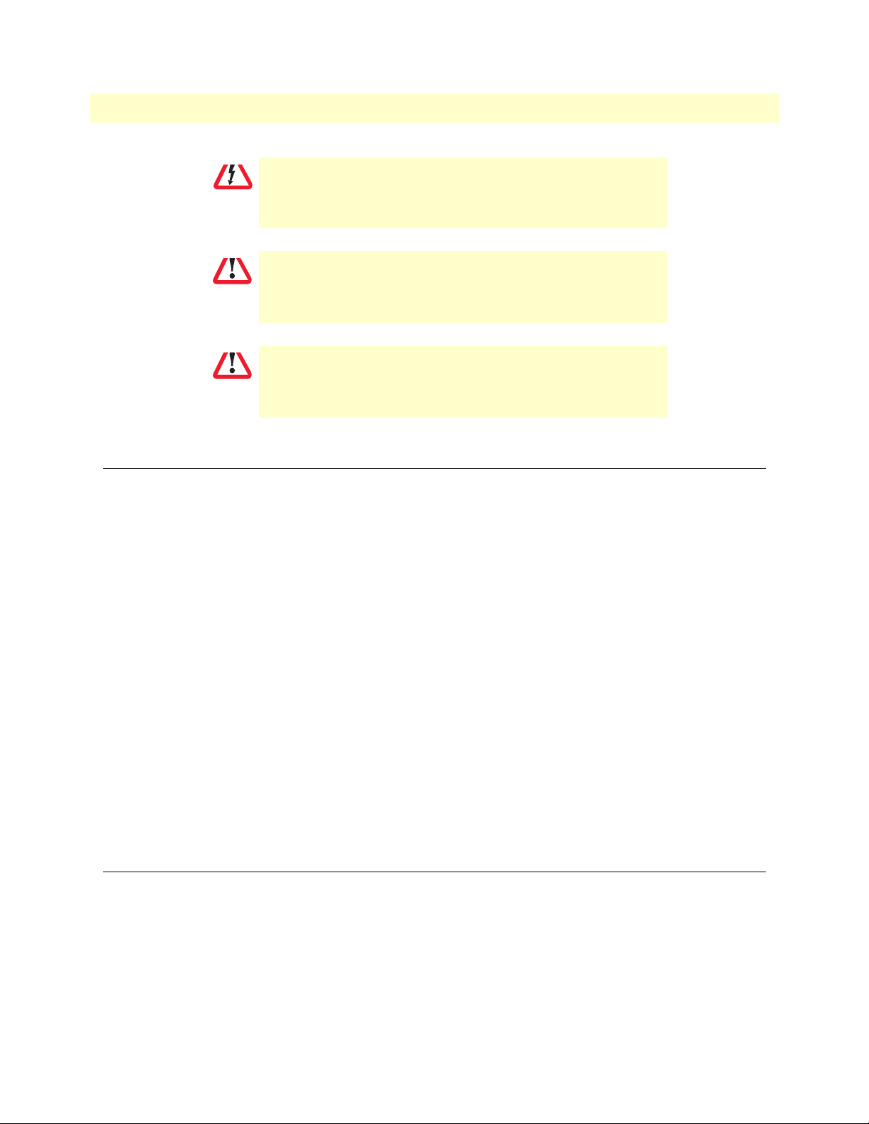
SmartNode 4830 DSL Series User Manual A • Compliance information
CAUTION
CAUTION
CAUTION
Disconnect all power before servicing.
The SmartNode product contains no user serviceable parts.
The mains outlet that is utilized to power the equipment must be
within 1 foot (3 meters) of the device and shall be easily accessible.
FCC Part 68 (ACTA) Statement (FXO ports)
This equipment complies with Part 68 of FCC rules and the requirements adopted by ACTA. On the bottom
side of this equipment is a label that contains—among other information—a product identifier in the format
US: AAAEQ##TXXXX. If requested, this number must be provided to the telephone company.
The method used to connect this equipment to the premises wiring and telephone network must comply with
the applicable FCC Part 68 rules and requirements adopted by the ACTA.
If this equipment causes harm to the telephone network, the telephone company will notify you in advance
that temporary discontinuance of service may be required. But if advance notice isn’t practical, the telephone
company will notify the customer as soon as possible. Also, you will be advised of your right to file a complaint
with the FCC if you believe it is necessary.
The telephone company may make changes in its facilities, equipment, operations or procedures that could
affect the operation of the equipment. If this happens the telephone company will provide advance notice in
order for you to make necessary modifications to maintain uninterrupted service.
If trouble is experienced with this equipment, for repair or warranty information, please contact our company.
If the equipment is causing harm to the telephone network, the telephone company may request that you disconnect the equipment until the problem is resolved.
Connection to party line service is subject to state tariffs. Contact the state public utility commission, public
service commission or corporation commission for information.
Industry Canada Notice (FXO ports)
This equipment meets the applicable Industry Canada Terminal Equipment Technical Specifications. This is
confirmed by the registration number. The abbreviation, IC, before the registration number signifies that registration was performed based on a Declaration of Conformity indicating that Industry Canada technical specifications were met. It does not imply that Industry Canada approved the equipment.
This Declaration of Conformity means that the equipment meets certain telecommunications network protective, operational and safety requirements. The Department does not guarantee the equipment will operate to
the user's satisfaction. Before installing this equipment, users should ensure that it is permissible to be con-
FCC Part 68 (ACTA) Statement (FXO ports) 51
Page 52

SmartNode 4830 DSL Series User Manual A • Compliance information
nected to the facilities of the local telecommunications company. The equipment must also be installed using
an acceptable method of connection. In some cases, the company’s inside wiring associated with a single line
individual service may be extended by means of a certified connector assembly (telephone extension cord). The
customer should be aware that compliance with the above condition may not prevent degradation of service in
some situations. Repairs to some certified equipment should be made by an authorized maintenance facility
designated by the supplier. Any repairs or alterations made by the user to this equipment, or equipment malfunctions, may give the telecommunications company cause to request the user to disconnect the equipment.
Users should ensure for their own protection that the ground connections of the power utility, telephone lines
and internal metallic water pipe system, are connected together. This protection may be particularly important
in rural areas.
CE Notice
This equipment conforms to the requirements of Council Directive 1999/5/EC on the approximation of the
laws of the member states relating to Radio and Telecommunication Terminal Equipment and the mutual recognition of their conformity.
The safety advice in the documentation accompanying this product shall be obeyed. the conformity to the
above directive is indicated by the CE sign on the device.
Authorized European Representative
D R M Green
European Compliance Services Limited.
Oakdene House, Oak Road
Watchfield,
Swindon, Wilts SN6 8TD, UK
CE Notice 52
Page 53

Appendix B Specifications
Chapter contents
DSP.......................................................................................................................................................................52
Voice connectivity................................................................................................................................................52
Ethernet interface .................................................................................................................................................52
ADSL Daughter Card (if applicable)...................................................................................................................52
G.SHDSL Daughter Card (if applicable).............................................................................................................53
PPP and Frame-Relay support..............................................................................................................................53
Voice processing (signaling dependent) ..............................................................................................................54
Fax and modem support .......................................................................................................................................54
Voice signaling.....................................................................................................................................................54
Voice routing—session product...........................................................................................................................55
IP services ............................................................................................................................................................55
Management.........................................................................................................................................................55
Operating environment.........................................................................................................................................56
Operating temperature ...................................................................................................................................56
Operating humidity ........................................................................................................................................56
System..................................................................................................................................................................56
Dimensions...........................................................................................................................................................56
Weight and power dissipation..............................................................................................................................56
Power supply........................................................................................................................................................56
Identification of the SmartNode devices via SNMP............................................................................................57
53
Page 54

SmartNode 4830 DSL Series User Manual B • Specifications
DSP
One or two 4-channel DSPs
Voice connectivity
2-wire Loopstart, RJ-11/12
Short haul loop 1.1 km @3REN
EuroPOTS (ETSI EG201 188)
Programmable AC impedance, feeding, and ring voltage; On-Hook Voltage 48VDC
Caller-ID Type-1FSK and ITU V.23/Bell 202 generation
Ethernet interface
One 10/100 Full Duplex/Autosensing Ethernet RJ-45 s
ADSL Daughter Card (if applicable)
ADSL: ADSL2+ ITU-T G.992.5 Annex A, M, B
Up to 24 Mbps
G.992.2 G.dmt, G.lite, G.992.3 Annex L, I, J
8 user configurable PVCs (UBR, CBR, VBR-rt selectable)
Supports PPPoE, PPPoA, IPoA
DSP 54
Page 55

SmartNode 4830 DSL Series User Manual B • Specifications
G.SHDSL Daughter Card (if applicable)
Table 14. G.SHDSL Daughter Card Specifications
Factor Specs
DSL • ITU-T G.991.2 (and Amendment 2)
• ITU-T G.991.2, Annex A, B, F, G
• Upgradable to ITU-T G.shdsl.bis—Annex F and G
• G.991.2 2/4 (1/2 pair) operation
• G.994.1 (G.hs) (per G.991.2)
• ITU-T G.991.2 Section E.9
(TPS-TC for ATM t ransport)
• ITU-T G.991.2 Section E.11
(TPS-TC for PTM transpor t)
DSL Connection 2GS models: RJ-45 (4-wire)
Management • I.610 OAM F4/F5
• Management interfaces: GUI and Telnet
• Software upgrade: GUI and TFTP
ATM Support • Classical IPoA (RFC 1577/2225)
• PPPoE Client (over ATM) (RFC 2516)
• IPoA (RFC 2684/1483)
• ATM AAL5 encapsulation
•Max. 8 PVCs
• User selectable VC MUX and LLC MUX (default)
• Configurable auto-connection
• ATM QoS: UBR (default), CBR, and VBR-rt, VBR-nrt,
UBR: per VC queuing
• Auto-configuration: TR-037 & ILMI 4.0
Interworking/Interoperability • G.SHDSL Interoperability:
- Alcatel
- NEC
- Lucent Anymedia
- Lucent Stinger
• BRAS Interoperability:
- Cisco
-Redback
PPP and Frame-Relay support
Frame-Relay (8 PVCs)
RFC1490, FRF.12 fragmentation
LMI, Q.933D, ANSI 617D, Gang of Four
PPP, PAP, CHAP, LCP, IPCP
G.SHDSL Daughter Card (if applicable) 55
Page 56

SmartNode 4830 DSL Series User Manual B • Specifications
Voice processing (signaling dependent)
Voice codes:
• G.711 A-Law/μ-Law (64 kbps)
• G.726 (ADPCM 40, 32, 24, 16 kbps)
• G.723.1 (5.3 or 6.3 kbps)
• G.729ab (8 kbps)
• Transparent pass through
G.168 echo cancellation
8 parallel voice connections
DTMF detection and generation
Carrier tone detection and generation
Silence suppression and comfort noise
Configurable dejitter buffer
Configurable tones (dial, ringing, busy)
Configurable transmit packet length
RTP/RTCP (RFC 1889)
Fax and modem support
G.711 transparent FAX
Fax over IP (FoIP)
T.38 Fax relay (9.6 k, 14.4 k)
Voice signaling
H.323v4
• RAS, H.225, H.245
• Fast-connect, early H.245
• Gatekeeper autodiscovery
• Alias registration
• Overlap sending
• Empty capability set (call transfer, hold)
• H.323v1 call transfer, hold
• H.323 GW and GK compatible
• H.323 Annex M3
Voice processing (signaling dependent) 56
Page 57

SmartNode 4830 DSL Series User Manual B • Specifications
SIP:
• SIPv2 (RFC3261, RFC3263)
• SIP call transfer, redirect, DTMF relay
Voice routing—session product
Local switching; Interface huntgroups
Routing Criteria:
• Interface
• Calling/called party number
• Time of day, day of week, date
Number manipulation functions
• Replace numbers; Add/remove digits
• Multiple remote gateways; PLAR
IP services
IPv4 product; RIPv1, v2 (RFC 1058 and 2453)
Programmable static routes
ICMP redirect (RFC 792); Packet fragmentation
DiffServe/ToS set or queue per header bits
Pocket Policing discards excess traffic
802.1p VLAN tagging
IPSEC AH & ESP Modes* (Requires license)
Manual Key; IKE optional
AES/DES/3DES Encryptions* (Requires license)
Management
Industry standard CLI with local console (RJ-45, RS-232, 9600 bps, 8, N, 1) and remote Telnet access
TFTP configuration & firmware loading
SNMP v1 agent (MIB II and private MIB)
Built-in diagnostic tools (trace, debug)
Java™ Applet; HPOV Integration with NNM
Voice routing—session product 57
Page 58
SmartNode 4830 DSL Series User Manual B • Specifications
Operating environment
Operating temperature
32–104°F (0–40°C)
Operating humidity
5–80% (non condensing)
System
CPU Motorola MPC875 operating at 66 MHz
Memory:
• 32 Mbytes SDRAM
• 8 Mbytes Flash
Dimensions
7.3W x 1.6H x 6.1D in. (18.5H x 4.1W x 15.5D cm)
Weight and power dissipation
See table 15.
Table 15. SmartNode weight and maximum power specifications
SmartNode model Weight Maximum power dissipation
SN4832/JSX/EUI 30.5 oz./500 g 7W
SN4834/JSX/EUI 30.5 oz./500 g 9W
SN4836/JSX/EUI 30.5 oz./500 g 11 W
SN4838/JSX/EUI 30.5 oz./500 g 13W
Power supply
External power supply, 100–240 VAC, 50/60 Hz, 200 mA
Operating environment 58
Page 59
SmartNode 4830 DSL Series User Manual B • Specifications
IMPORTANT
Identification of the SmartNode devices via SNMP
All SmartNode devices have assigned sysObjectID (.iso.org.dod.internet.mgmt.mib-2.system.sysObjectID)
numbers (see table 16).
Table 16. SmartNode Models and their Unique sysObjectID
SmartNode Model SysObjectID
SN4834-JS .iso.org.dod.internet.private.enterprises.patton.products.sn4xxx.1
1.3.6.1.4.1.1768.2.4.5.1
SN4836-JS .iso.org.dod.internet.private.enterprises.patton.products.sn4xxx.3
1.3.6.1.4.1.1768.2.4.5.3
SN4838-JS .iso.org.dod.internet.private.enterprises.patton.products.sn4xxx.4
1.3.6.1.4.1.1768.2.4.5.4
SN4834-2JS2JO .iso.org.dod.internet.private.enterprises.patton.products.sn4xxx.9
1.3.6.1.4.1.1768.2.4.5.9
SN4836-4JS2JO .iso.org.dod.internet.private.enterprises.patton.products.sn4xxx.10
1.3.6.1.4.1.1768.2.4.5.10
SN4838-4JS4JO .iso.org.dod.internet.private.enterprises.patton.products.sn4xxx.11
1.3.6.1.4.1.1768.2.4.5.11
SN4832-JO .iso.org.dod.internet.private.enterprises.patton.products.sn4xxx.15
1.3.6.1.4.1.1768.2.4.5.15
SN4834-JO .iso.org.dod.internet.private.enterprises.patton.products.sn4xxx.16
1.3.6.1.4.1.1768.2.4.5.16
According to table 16, an SNMP get request to .iso.org.dod.internet.mgmt.mib-2.system.sysObjectID of a SmartNode 4834-JS device reads out a numeric OID of
1.3.6.1.4.1.1768.2.4.5.1, which represents a SmartNode 4834
device. The mapping of the sysObjectID to each of the SmartNode model is realized with the SmartNode
product identification MIB.
The SNMP agent running in SmartWare is SNMP version 1
(SNMPv1) compliant. SNMP version 2 (SNMPv2) and SNMP version 3 (SNMPv3) are not currently supported.
Identification of the SmartNode devices via SNMP 59
Page 60

Appendix C Cabling
Chapter contents
Introduction..........................................................................................................................................................59
Serial console.......................................................................................................................................................59
Ethernet 10Base-T and 100Base-T......................................................................................................................60
Analog FXS..........................................................................................................................................................61
Analog FXO.........................................................................................................................................................62
DSL......................................................................................................................................................................63
60
Page 61
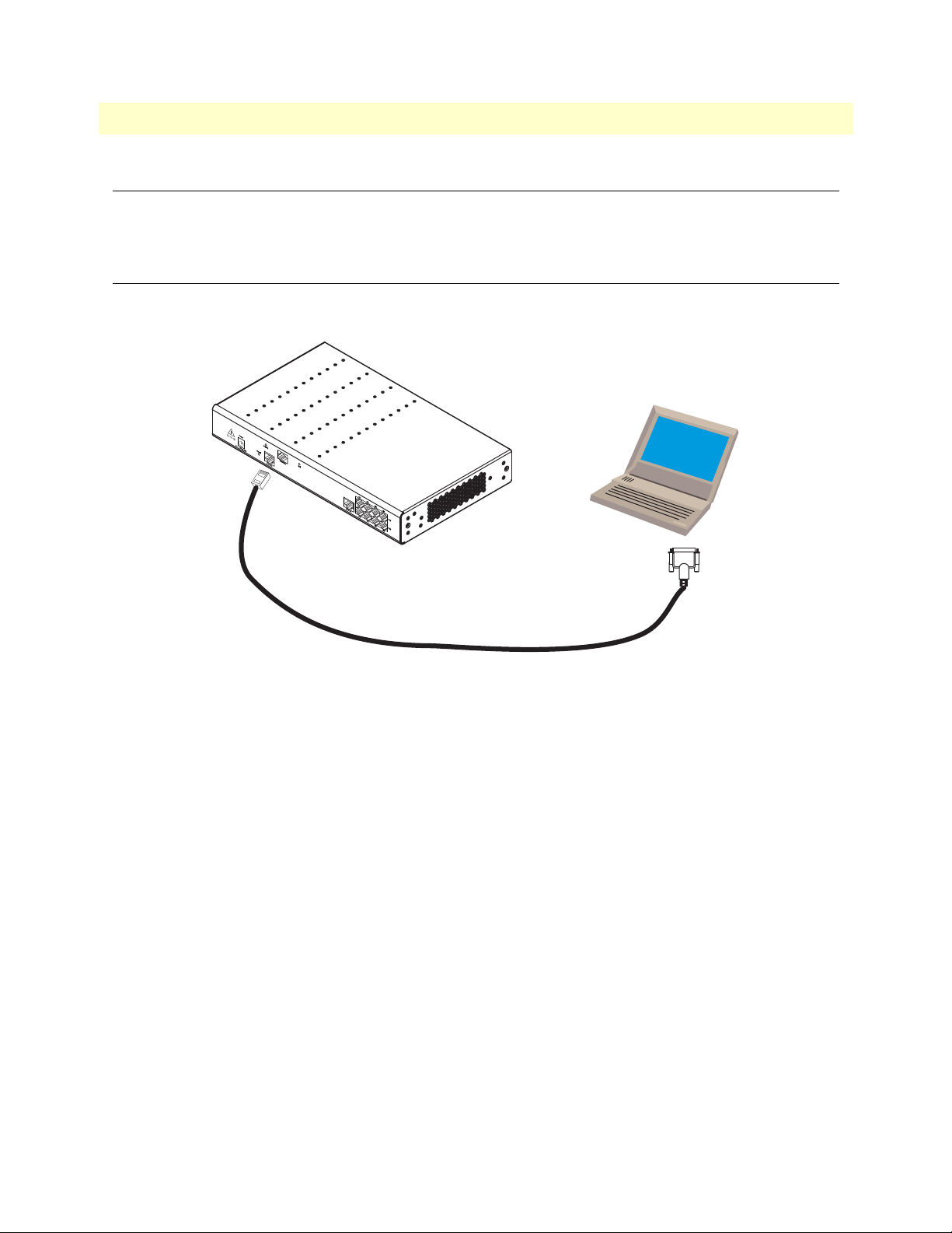
SmartNode 4830 DSL Series User Manual C • Cabling
Introduction
This section provides information on the cables used to connect the SmartNode and the interface cards to the
existing network infrastructure and to third party products.
Serial console
The SmartNode can be connected to a serial terminal over its serial console port, as depicted in figure 14.
Serial Terminal
Note
Note A Patton Model 16F-561 RJ45 to DB-9 adapter is included with
each SmartNode 4830 Series device
Figure 14. Connecting a serial terminal
See section “Console port” on page 67 for console port pin-outs.
Introduction 61
Page 62
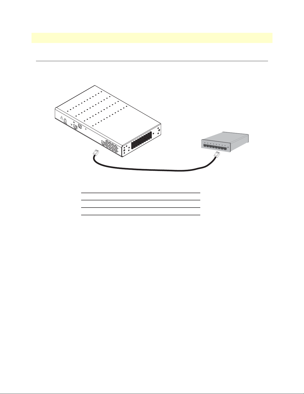
SmartNode 4830 DSL Series User Manual C • Cabling
Ethernet 10Base-T and 100Base-T
Ethernet devices (10Base-T/100Base-T) are connected to the SmartNode over a cable with an RJ-45 plug. The
Ethernet port supports auto-MDI-X, so any standard Ethernet cable will work properly.
Hub
Straight-through cable
SmartNode: RJ-45, male
Tx+
1
Tx-
2
Rx+
3
Rx-
6
Hub/switch: RJ-45, male
1 Rx+
2 Rx3 Tx+
6 Tx-
Figure 15. Ethernet straight-through
Ethernet 10Base-T and 100Base-T 62
Page 63
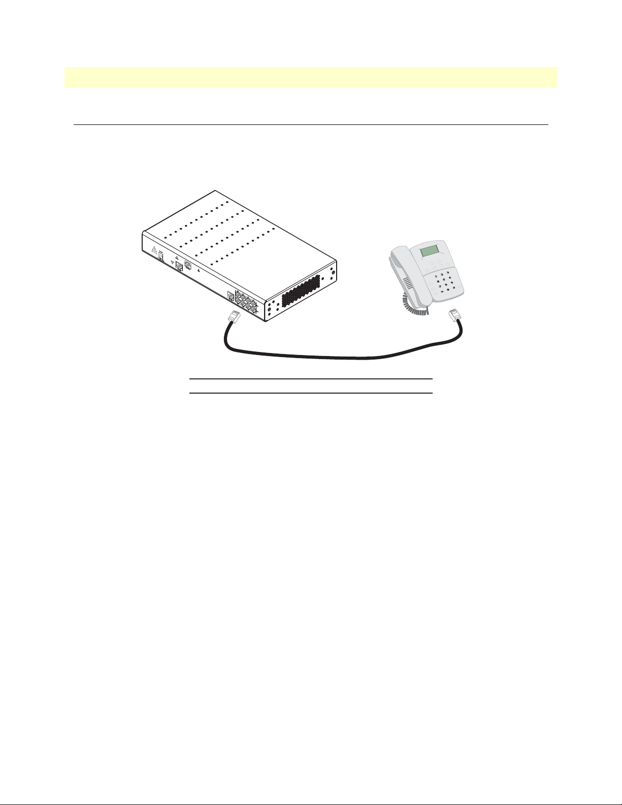
SmartNode 4830 DSL Series User Manual C • Cabling
Analog FXS
Applicable to SmartNodes equipped with FXS ports. The FXS ports are connected to analog terminals
(phones, fax machines, answering machines) via cables terminated with RJ-11 connectors (see section “FXS
port” on page 68 for details on port pinouts).
Phone
RJ-11, male RJ-11, male
Ring (-) 3
Tip (+) 4
3 Ring (-)
4 Tip (+)
Figure 16. Connecting an FXS device
Analog FXS 63
Page 64
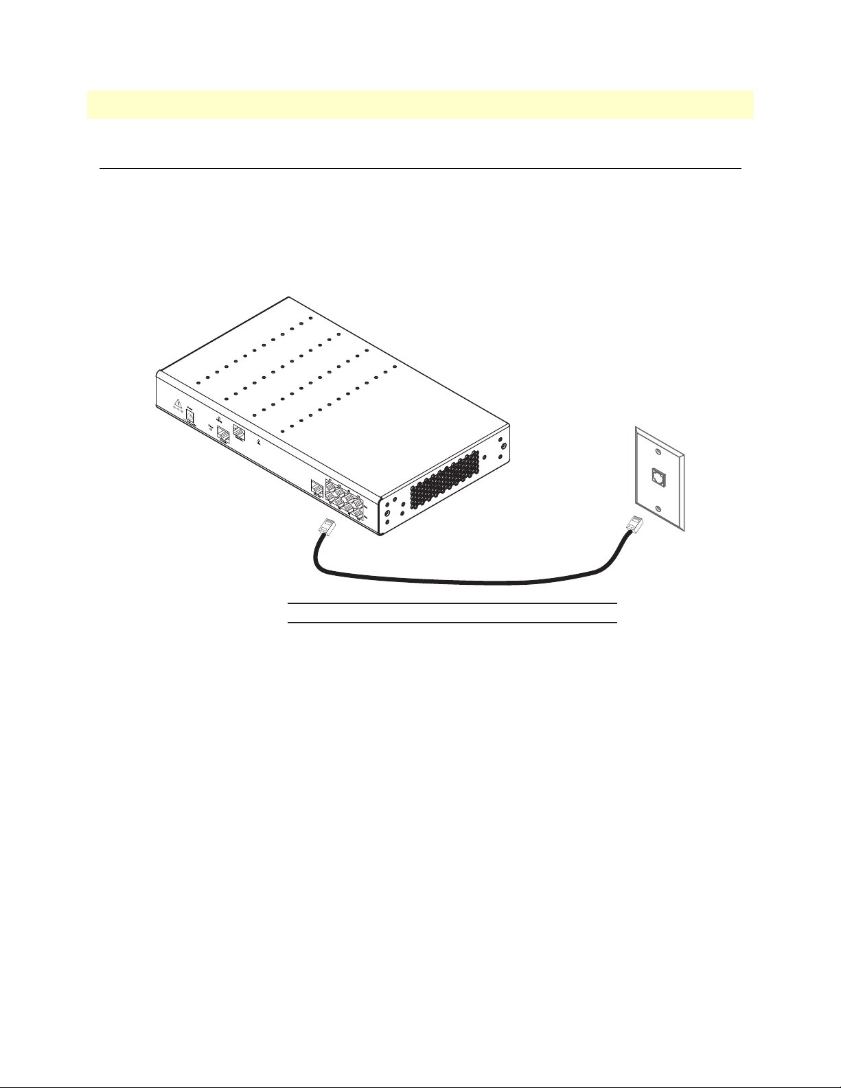
SmartNode 4830 DSL Series User Manual C • Cabling
Analog FXO
Applicable to SmartNodes equipped with FXO ports. The FXO ports are connected to analog phone lines via
cables terminated with RJ-11 connectors (see section “FXO port” on page 68 for details on port pinouts).
Note The phone line socket (connector type and pinout) available from the pub-
lic network vary from country to country. Refer to technical information
available from your local operator for additional cabling information.
PSTN
wall plate
RJ-11, male RJ-11, male
Ring (-) 3
Tip (+) 4
3 Ring (-)
4 Tip (+)
Figure 17. Connecting to an FXO line socket
Analog FXO 64
Page 65
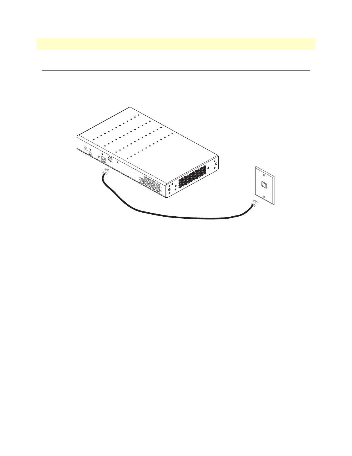
SmartNode 4830 DSL Series User Manual C • Cabling
DSL
The DSL interface connects to the analog or ISDN telecom line coming to your house. Depending on the
country and type of installation, a frequency splitter device may be inserted between the phone outlet and the
SmartNode, splitting the DSL signal from the phone signal.
Figure 18. Connecting the DSL cable
DSL 65
Page 66

Appendix D Port pin-outs
Chapter contents
Introduction .........................................................................................................................................................67
Console port ........................................................................................................................................................67
Ethernet 10Base-T and 100Base-T port ..............................................................................................................67
FXS port ..............................................................................................................................................................68
FXO port .............................................................................................................................................................68
ADSL/G.SHDSL Port (RJ-45) ............................................................................................................................68
66
Page 67
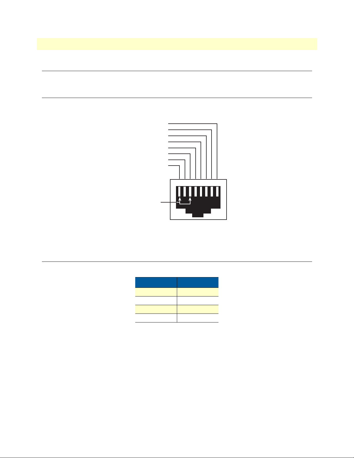
SmartNode 4830 DSL Series User Manual D • Port pin-outs
12345678
8–RTS (N/C)
7–CTS (N/C)
6–TD
5–RD
4–SG
3–DTR
2–CD (N/C)
1–DSR
Pins 1 & 3 are
connected together
Introduction
This section provides pin-out information for the ports of the SmartNode.
Console port
Configuration settings: 9600 bps, 8 bits, no parity, 1 stop bit, no flow control
Figure 19. EIA-561 (RJ-45 8-pin) port
Note
N/C means no internal electrical connection.
Ethernet 10Base-T and 100Base-T port
Table 17. RJ-45 socket
Pin Signal
1 TX+
2 TX-
3 RX+
6 RX-
Note Pins not listed are not used.
Introduction 67
Page 68
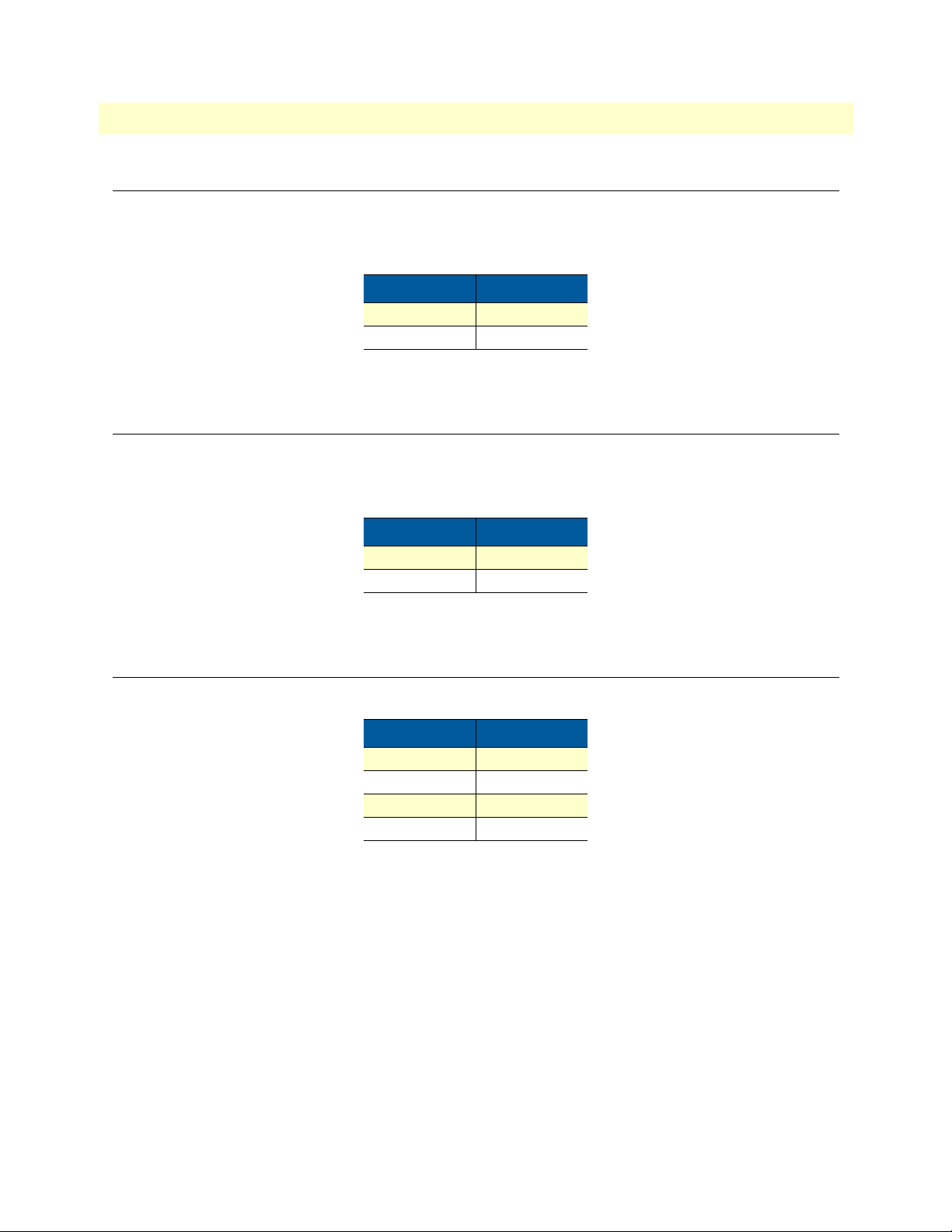
SmartNode 4830 DSL Series User Manual D • Port pin-outs
FXS port
The FXS ports use an RJ-11 connector with 6 positions. The middle two positions, 3 and 4, are used according
to table 18.
Table 18. RJ-11 socket
Pin Signal
3 Ring (-)
4 Tip (+)
Note Pins not listed are not used.
FXO port
The FXO ports use an RJ-11 connector with 6 positions. The middle two positions, 3 and 4, are used according to table 19.
Table 19. RJ-11 socket
Pin Signal
3 Ring (-)
4 Tip (+)
Note Pins not listed are not used.
ADSL/G.SHDSL Port (RJ-45)
Table 20. RJ-45 DSL port
Pin Signal
3 Tip 2
4 Tip 1
5 Ring 1
6 Ring 2
FXS port 68
Page 69

Appendix E Installation checklist
Chapter contents
Introduction..........................................................................................................................................................68
69
Page 70
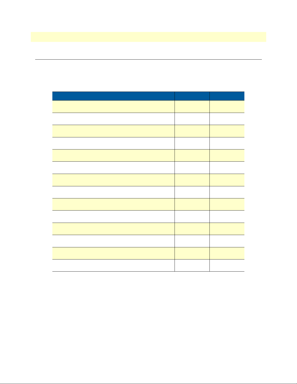
SmartNode 4830 DSL Series User Manual E • Installation checklist
Introduction
This appendix lists the tasks for installing a SmartNode 4830 DSL Series Analog VoIP IAD (see table 21).
Make a copy of this checklist and mark the entries as you complete each task. For each SmartNode 4830 DSL
Series IAD, include a copy of the completed checklist in your site log.
Table 21. Installation checklist
Task Verified by Date
Network information available & recorded in site log
Environmental specifications verified
Site power voltages verified
Installation site pre-power check completed
Required tools available
Additional equipment available
All printed documents available
SmartWare release & build number verified
Rack, desktop, or wall mounting of chassis completed
Initial electrical connections established
ASCII terminal attached to console port
Cable length limits verified
Initial configuration performed
Initial operation verified
Introduction 70
 Loading...