

Patterson-Kelley THERMIFIC MODU-FIRE Supplement Manual
MOD-02
©2002 Patterson-Kelley, A Harsco Company
PATTERSON-KELLEY
THERMIFIC
®
MODU-FIRE® GAS-FIRED BOILER
Supplement to the standard Installation and
Owner's Manual (TBIG - Latest Edition)
C.S.A Design-Certified
Complies with ANSI Z21.13/CSA 4.9
Gas-Fired Low Pressure Steam and Hot Water Boilers
Installation Date: _______________________
ASME Code, Section IV
Certified by Patterson-Kelley
C.S.A Design-Certified
Complies with ANSI Z21.13/CSA 4.9
Gas-Fired Low Pressure Steam and Hot Water Boilers
100 Burson Street, P.O. Box 458,
East Stroudsburg, PA 18301
Telephone: (877) 728-5351, Facsimile: (570) 476-7247
www.pkboilers.com

Modu-Fire® Gas-Fired Boiler Table of Contents
1.0 INTRODUCTION................................. 1
2.0 SAFETY............................................... 1
2.1 General................................................1
2.2 Training................................................1
2.3 Safety Features ...................................1
2.4 Safety Labels.......................................1
2.5 Safety Precautions...............................1
2.5.1 Electrical Hazards..........................1
2.5.2 Burn, Fire, and Explosion Hazards..1
2.5.3 Crush Hazards...............................1
2.5.4 Chemical Hazards .........................1
2.5.5 Pressure Hazards..........................1
2.5.6 Slip, Fall Hazards...........................1
3.0 INSTALLATION................................... 2
3.1 Receiving and Storage ........................2
3.1.1 Initial Inspection..............................2
3.1.2 Storage Prior to Installation ...........2
3.2 Compliance with Codes.......................2
3.3 Setup ...................................................2
3.3.1 Foundation.....................................2
3.3.2 Placement......................................2
3.3.3 Clearances.....................................2
3.4 Electrical Connections.........................2
3.5 Combustion Air....................................2
3.6 Flue Venting.........................................2
3.6.1 Vent Elbows...................................2
3.7.2 Gas Bleeds and Vents...................3
3.8 Boiler Water Piping..............................3
3.8.1 Piping Design.................................3
3.8.2 Boiler Inlet and Outlet Connections..3
3.8.3 Boiler Water Piping by Installer......3
3.8.4 Flushing and Filling........................3
3.9 Burner and Ignition System .................3
3.9.1 Inspection ......................................3
3.10 Pre-Start Check List...........................3
3.11 Safety Checks....................................3
3.11.1 Test of Ignition Safety System.....3
3.11.2 Test of Low Water Cut-off............4
3.11.3 Test of High-Limit Control............4
3.11.4 Test of Gas Pressure Switch.......4
3.12 Initial Adjustments..............................4
3.12.1A – Configuring the Controller .......4
3.12.2 Air Flow Adjustments...................9
3.12.3 Gas Pressure Adjustment............9
4.0 OPERATION......................................10
4.1 General..............................................10
4.1.1 Control Panel Front......................10
4.2 Lighting and Shut-Down Procedures.10
4.2.1 Lighting Procedures.....................11
4.2.2 Normal Shut Down Procedures...11
4.2.3 Emergency Shut Off ....................11
4.3 Typical Boiler Operating Conditions ..11
3.6.2 Barometric Damper........................2
3.6.3 Barometric Damper Location.........2
3.6.4 Flue Connection.............................2
3.6.5 Vent Termination ...........................2
3.6.6 Removing an Existing Boiler..........2
3.7 Gas Piping............................................2
3.7.1 Gas Supply Piping by Installer.......3
5.0 MAINTENANCE.................................12
5.1 Maintenance and Inspection Schedule 12
5.1.1 Daily.............................................12
5.1.2 Weekly.........................................12
5.1.3 Monthly (During Operation) .........12
5.1.4 Semi-Annually..............................12
5.1.5 Annually.......................................12

Modu-Fire® Gas-Fired Boiler Table of Contents
5.2 Cleaning the Burner...........................12
5.2.1 Semi-Annual Cleaning.................12
5.2.2 Annual Cleaning ..........................12
5.3 Removing the Exchanger ..................13
5.4 After All Repairs or Maintenance.......13
5.5 SEQUENCE OF OPERATION ...........13
5.5.1 STANDARD MODULATING........13
5.5.2 IRI MODULATING .......................14
5.6 TROUBLE SHOOTING.......................15
5.6.1 Loss of Power..............................15
5.6.2 Loss of Water Flow......................15
5.6.3 Low Gas Pressure .......................15
5.6.4 High Water Temperature .............15
5.6.5 Low Air.........................................15
5.6.6 Ignition Failure.............................15
5.6.7 Flame Failure...............................15
6.0 PARTS/TECHNICAL SUPPORT........16
6.1 Schematic Diagrams...........................16
Standard Unit w/ Siemens Control.........17
Standard Unit w/ Remote Control..........18
IRI with Siemens Control.......................19
IRI with Remote Control.........................20
6.2 Boiler Parts List..................................21
6.2.1 Main Assembly ............................21
6.2.2 Control Panel...............................22
6.2.3 Gas Train.....................................23
7.0 LIMITED WARRANTY........................ 24
REMEDY ..................................................24
EXCLUSIONS...........................................24
THIRD-PARTY WARRANTIES.................24
SEVERABILITY........................................24
NO OTHER WARRANTIES......................24

Modu-Fire® Gas-Fired Boiler Introduction/Safety
1.0 INTRODUCTION
The P-K MODU-FIRE® Gas Fired Boiler is a
revolutionary advance; Patterson-Kelley now
combines full-modulation burner control with our
time-tested modular hot water boiler design. The
result is “modular full-modulation”- Modu-Fire!
This new hybrid boiler combines the best of our
earlier designs with a generation of burner and
control technology. You will achieve even higher
part load efficiencies – but without the complexity
you might expect in this type of high performance
boiler. High performance made simple and
dependable for years of trouble-free operation.
This manual covers installation of the P-K MODU-
®
FIRE
Boiler Series 1000, 1500, and 2000. The
model numbers may be followed by a prefix or
suffix letter in some cases to indicate special
features or different options. While details may
2.0 SAFETY
(Refer To TBIG Latest Edition)
2.1
GENERAL
(Refer To TBIG Latest Edition)
2.2
TRAINING
(Refer To TBIG Latest Edition)
2.3
SAFETY FEATURES
(Refer To TBIG Latest Edition)
SAFETY LABELS
2.4
(Refer To TBIG Latest Edition)
2.5
SAFETY PRECAUTIONS
(Refer To TBIG Latest Edition)
2.5.1 Electrical Hazards
(Refer To TBIG Latest Edition)
differ slightly, basic operation is the same for all
models. Boilers are built to operate with natural
gas. Check the rating plate for the correct gas flow
rate.
The boiler is only a part of the complete heating
system. This boiler may be fully operational and yet
because of poor circulation, controls, or other
operating characteristics, not deliver heat to the
desired location. Additional equipment such as
temperature sensors, pumps, flow switches,
balancing valves and check valves will be required
for satisfactory operation of any system. PattersonKelley cannot be responsible for the design or
operation of such systems and a qualified engineer
or contractor must be consulted.
2.5.2 Burn, Fire, and Explosion Hazards
(Refer To TBIG Latest Edition)
2.5.3 Crush Hazards
(Refer To TBIG Latest Edition)
2.5.4 Chemical Hazards
(Refer To TBIG Latest Edition)
2.5.5 Pressure Hazards
(Refer To TBIG Latest Edition)
2.5.6 Slip, Fall Hazards
(Refer To TBIG Latest Edition)
1

Modu-Fire® Gas-Fired Boiler Installation
3.0 INSTALLATION
(Refer To TBIG Latest Edition)
3.1
RECEIVING AND STORAGE
(Refer To TBIG Latest Edition)
3.1.1 Initial Inspection
(Refer To TBIG Latest Edition)
3.1.2 Storage Prior to Installation
(Refer To TBIG Latest Edition)
3.2
COMPLIANCE WITH CODES
(Refer To TBIG Latest Edition)
3.3
SETUP
(Refer To TBIG Latest Edition)
3.3.1 Foundation
(Refer To TBIG Latest Edition)
3.3.2 Placement
(Refer To TBIG Latest Edition)
3.3.3 Clearances
(Refer To TBIG Latest Edition)
3.4
ELECTRICAL CONNECTIONS
(Refer To TBIG Latest Edition)
3.5
COMBUSTION AIR
(Refer To TBIG Latest Edition)
3.6
FLUE VENTING
For boilers connected to gas vents or chimneys, vent
installations shall be in accordance with Part 7,
Venting of Equipment, of the National Fuel Gas
Code, ANSI Z223.1, or applicable provisions of the
local building codes.
In Canada, the boiler is certified for installation with
a “Power Venter” by the Canadian Gas Association
when installed with the “listed accessories.”
Consult your local distributor for information on
proper selection. The venting system and the
horizontal portions of the venting system shall be
supported to prevent sagging.
Consult your local vent supplier for correct vent
sizing and structural support requirements. Vent
diameter is dictated by the length and height of
horizontal and vertical portions of the vent
installation and the materials of construction.
Correct sizing should be based on High fire input at
a nominal -.04" W.C. draft pressure at the boiler
outlet with a gross stack temp of 325º F and CO
2
ratings at 7.5%.
3.6.1 Vent Elbows
(Refer To TBIG Latest Edition)
3.6.2 Barometric Damper
This boiler is certified for operation without a
barometric damper. However, some venting
installations may require a barometric damper for
excessive draft conditions. (Not supplied by
factory.)
3.6.3 Barometric Damper Location
(Refer To TBIG Latest Edition)
3.6.4 Flue Connection
(Refer To TBIG Latest Edition)
3.6.5 Vent Termination
(Refer To TBIG Latest Edition)
3.6.6 Removing an Existing Boiler
(Refer To TBIG Latest Edition)
This boiler is Category II as it is defined in ANSI
Z21.13/CSA 4.9 latest edition.
2
3.7
GAS PIPING
(Refer To TBIG Latest Edition)
Modu-Fire® Gas-Fired Boiler Installation
3.7.1 Gas Supply Piping by Installer
(Refer To TBIG Latest Edition)
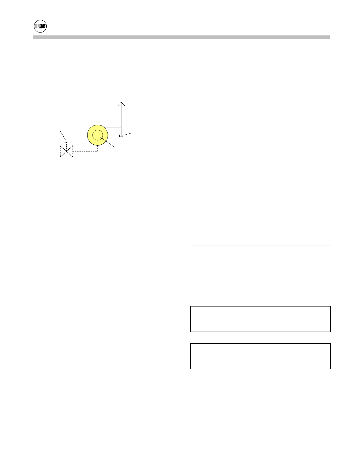
3.7.2 Gas Bleeds and Vents
Vent to
Outside Air
Gas Shutoff
(on Boiler
Gas Bleeds and Vents
Air Gas
Ratio
Control
Drip Leg
If your unit is equipped with a diaphragm gas valve,
the bleed line must be vented to the outdoors.
Maintain size of vent line consistent with vent
connection size.
Gas vents to outdoor air must be provided for the
Air Gas Ratio Control (AGRC). This connection is
labeled COMBUSTION/ATMOSPHERE. The pilot
regulator is equipped with a vent limiting device and
does not require external venting!
Gas Vents by Installer
Note: Provide a drip leg, as shown, in the vent line.
All vent lines should be pitched up at all times to
prevent building a trap into the vent line.
Note: The vent line connection on the Air Gas
Ratio Control must be piped to outdoor air by the
installer in accordance with the National Fuel Gas
Code ANSI Z223.1, latest edition, Sections 2.8.4
and 2.9.7.
If a N.O. (normally open) vent valve is provided, it
must be vented independently of any other bleeds
and vents. Discharge of vent lines should be
protected by an insect screen.
BOILER WATER PIPING
3.8
3.8.1 Piping Design
(Refer To TBIG Latest Edition)
3.8.2 Boiler Inlet and Outlet Connections
(Refer To TBIG Latest Edition)
3.8.3 Boiler Water Piping by Installer
(Refer To TBIG Latest Edition)
3.8.4 Flushing and Filling
(Refer To TBIG Latest Edition)
3.9
BURNER AND IGNITION SYSTEM
(Refer To TBIG Latest Edition)
3.9.1 Inspection
(Refer To TBIG Latest Edition)
3.10
PRE-START CHECK LIST
(Refer To TBIG Latest Edition)
SAFETY CHECKS
3.11
The following checks of safety systems must be
made before putting the boiler into normal
operation.
Before firing the boiler refer to
Sections 4.1 and 4.2
for information on the use of the controls, lighting,
and shut-down procedures.
WARNING!
Never attempt to operate a boiler that has failed to
pass all the safety checks described below.
WARNING!
After checking controls by manual adjustment, make
sure they are always reset to their proper settings.
3.11.1 Test of Ignition Safety System
Test the ignition system safety shutoff as follows:
(Refer To TBIG Latest Edition)
3
1. Close downstream gas cock.

Modu-Fire® Gas-Fired Boiler Installation
2. With the main gas cock (inlet manual gas valve)
open and the pilot gas cock open, the burner
should be cycled on. After all the safety limits
on gas pressure, water flow and temperature are
satisfied, the blower will run and pre-purge the
boiler.
3. When air flow is established, the ignition
transformer and pilot will operate. Both
functions will be indicated by separate green
lights on the flame safeguard.
4. If a satisfactory pilot is established, the spark
will terminate and the pilot will remain on,
alone, for 10 seconds.
5. After 10 seconds, the green "Main” light on the
flame safeguard will go on; gas will not flow
since the downstream cock is closed. The
"Pilot" will remain on, along with the "Main
Gas", for another 10 seconds and then go out.
Since the gas cock is closed, at this point there
will be no main flame signal and the flame
safeguard programmer will assume a “Flame
Failure” and go to a "lockout" mode. Lockout
will require manual reset of the flame safeguard.
After completing this test, turn off the boiler and
reopen the downstream gas cock.
3.11.2 Test of Low Water Cut-off
(Refer To TBIG Latest Edition)
3.11.3 Test of High-Limit Control
Fire the boiler and test the high limit control as
follows:
With the main burner operating, turn down the
temperature setting on the "high-limit" thermostat
until the main burner shuts off. The high-limit
switch must be manually reset after testing. This
check should also be made for the "Operating
Temperature" control (the green "Heat" indicator
will go out) (see next section for Modulating Units).
Readjust thermostats to desired operating
temperature and set high-limit temperature, typically
20º F above operating temperature.
3.11.4 Test of Gas Pressure Switch
(Refer To TBIG Latest Edition)
3.12
INITIAL ADJUSTMENTS
3.12.1A – Configuring the Controller
Operating Modes:
Internal Setpoint
Night Setback
Outdoor Air Reset
Analog Input Setpoint (See Section 3.12.1B.)
Analog Input Direct Drive (Multiple boiler
Controls)
Definitions:
SP1- Setpoint 1:...................This is the primary
setpoint of the boiler.
SP2- Setpoint 2 :...................An alternate setpoint.
Available through the
night setback contact.
dSP- Differential Setpoint : ..An alternate setpoint
differential from SP1.
Available through the
night setback contact.
tA- Air temperature: ............Measurement of
outside air
temperature.
SP.E- External Setpoint:.......Measurement of the
external setpoint.
HyS1:....................................Low temperature
differential.
HyS3:....................................High temperature
differential.
Internal Setpoint
The boiler water outlet temperature is controlled to
SP1 (setpoint 1) and the boiler modulates to
maintain SP1 subject to the upper and lower
temperature differentials and the upper and lower
setpoint limit.
4
Modu-Fire® Gas-Fired Boiler Installation
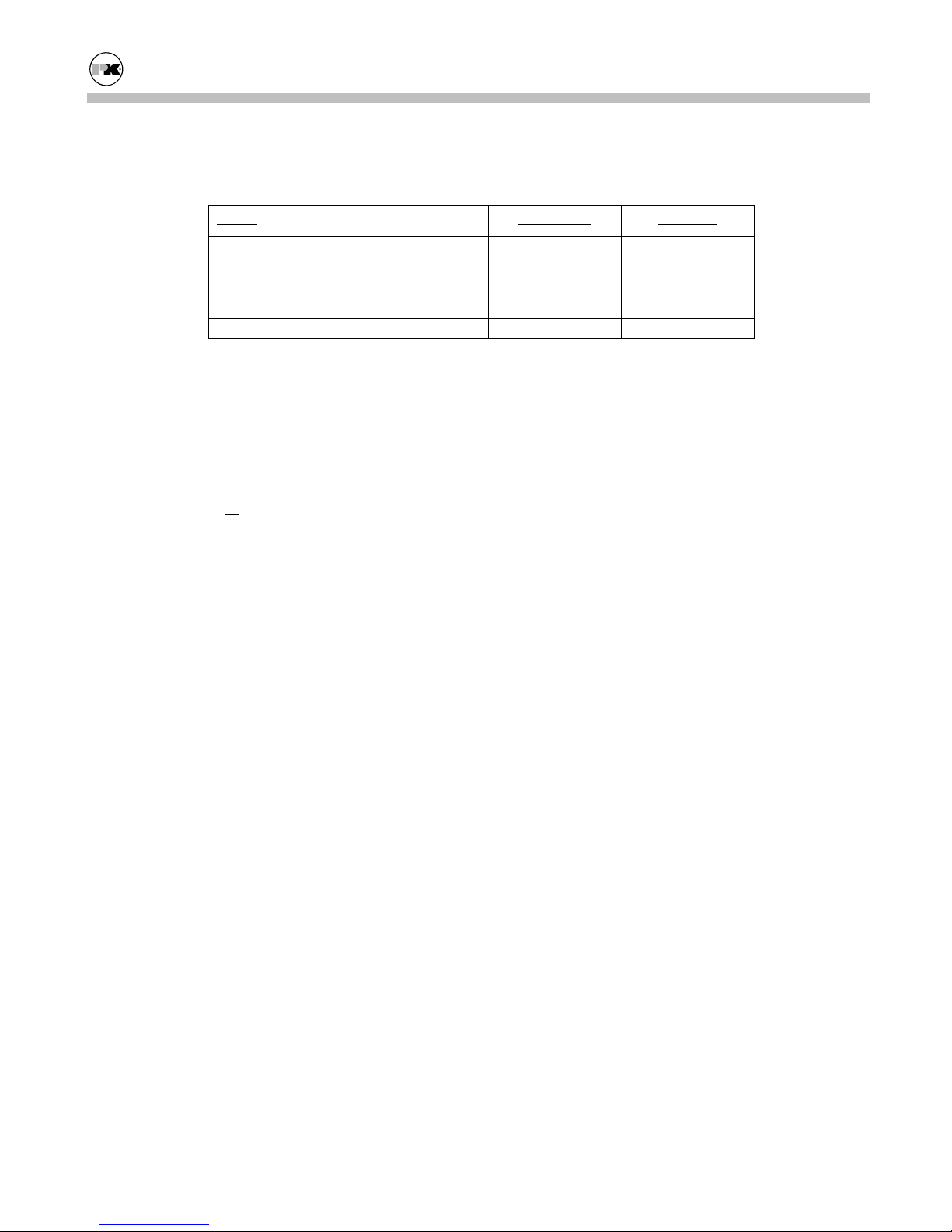
For example, assume the following settings:
ITEM DISPLAY VALUE
SETPOINT 1 SP1 160
LOW TEMP DIFFERENTIAL HyS1 -5
HIGH TEMP DIFFERENTIAL HyS3 12
LOW TEMP SETPOINT SPL 150
HIGH TEMP SETPOINT SPH 195
The boiler will modulate to try to maintain 160
If the temperature increases to 172
Setpoint 1 (SP1)
(HyS3)
12, it will shut off. Once it shuts off, it will
160 + High Temp Differential
o
F which is
not restart until the temperature drops to 155
which is Setpoint 1 (SP1)
Differential (Hys1)
160 + Low Temp
-5. The Low Temp Setpoint
o
F.
o
F
(SPL) prevents the operator from setting Setpoint 1
(SP1) lower than Low Temp Setpoint (SPL)
150.
The High Temp Setpoint (SPH) prevents the
operator from setting Setpoint 1 (SP1) higher than
the High Temp Setpoint (SPH)
195.
Alternate Setpoint
The control must be configured for night setback.
(See the configuration menu.) When the Alternate
Setpoint contact is closed the boiler switches to its
alternate setpoint.
The alternate setpoint can be determined by several
different values. It can be a fixed alternate setpoint
SP2. It can be a fixed differential from SP1 called
dsP. dsP will “offset” the main setpoint SP1 by the
value of dsP. dsP can be positive or negative.
The boiler modulates to maintain this setpoint. The
boiler functions as indicated in internal setpoint;
however SP1 is determined by the outdoor air
temperature.
The setpoint SP1 is reset using a linear relationship
with outdoor air temperature. As the outdoor air
temperature drops the setpoint SP1 is increased a
proportional amount. This increase is determined
by the Heating Slope H. (See Table 1 at the end of
this section.) For example if H is set at 1 then for
every degree the outdoor air temp drops, the
setpoint SP1 will increase 1 degree.
This heating curve has a reference temperature of
68°. This reference can be offset using the Parallel
shift parameter P. (See Table 1 at the end of this
section.) If P is set to 0 the setpoint SP1 will be 68°
when the outdoor temp is 68°. If P is set to 10, the
setpoint SP1 will be 78° when the outdoor temp is
68°. The minimum setpoint of the boiler is limited
by the control. In the above example the actual
setpoint SP1 of the boiler will not go below 150°.
Analog Input Setpoint
The Alternate Setpoint can also be determined by an
external analog source such as a 4-20 mA signal.
Outdoor Air Reset
The control must be configured for outdoor air reset.
(See the configuration menu.)
The setpoint of the boiler is controlled by an
outdoor temperature sensor. As the outdoor
temperature falls the setpoint of the boiler is
increased.
5
The control must be configured for external
setpoint. (See the configuration menu.)
The setpoint of the boiler is controlled by an
external signal. The boiler functions as described
with the internal setpoint, using the value
determined by the external analog signal.
Analog Input Direct Drive
The firing rate of the boiler is controlled by an
external analog signal, usually from a multiple
Modu-Fire® Gas-Fired Boiler Installation
boiler control. The boiler turns on and off as
directed by the external control.
An operating limit control ensures that the boiler
temperature does not exceed the set value.
Refer also to Section 3.12.1B.
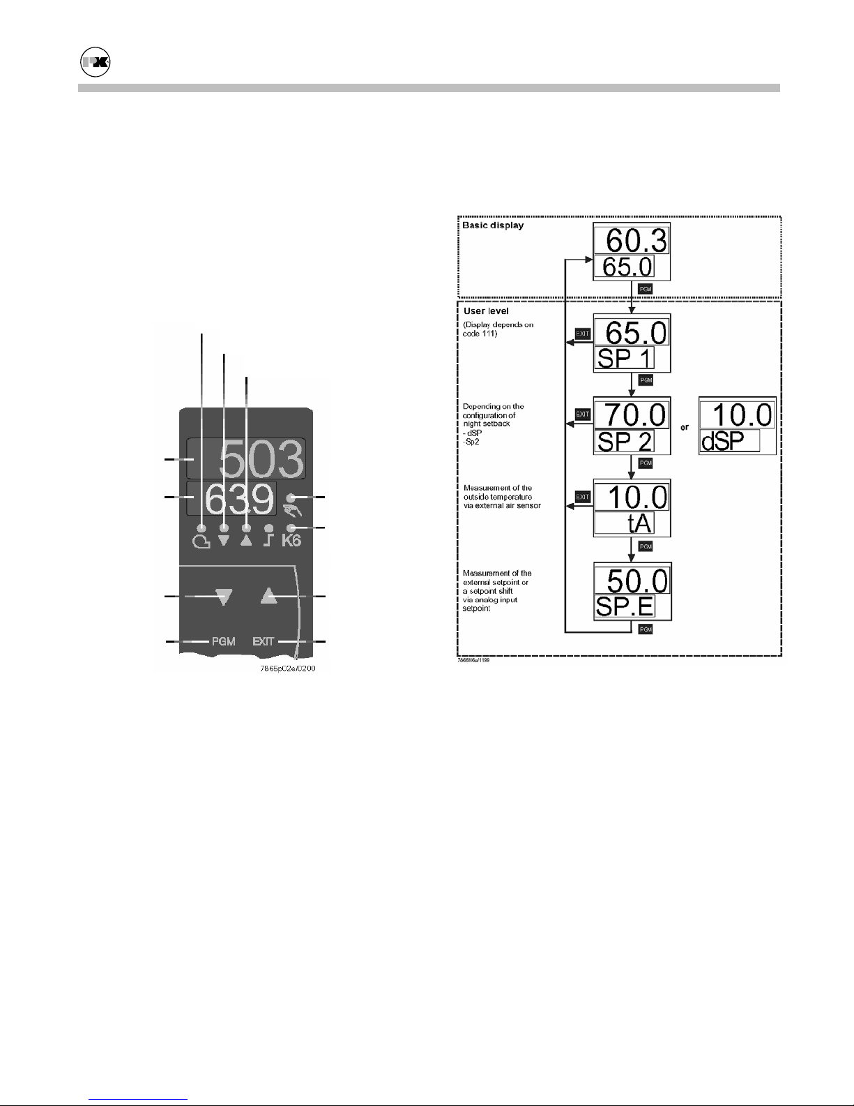
Use of the Controller
Actual Value
Display (red)
Setpoint
Display
(green)
Operating Limit Closed
Firing Rate Decreasing
Firing Rate Increasing
Manual
Operation
Alarm Relay
Energized
The following table indicates the menu options
available from each level. The options available
depend on the operating mode of the boiler.
Decrease
Value
PROGRAM
Button
Increase
Value
EXIT
Button
The diagram shows the RWF40 after switching on
power. This condition is called the basic display.
The actual value and the currently active setpoint
are shown here. Manual operation, self-setting, and
the user, parameter, and configuration levels can be
activated from here.
Operation of the Control:
The temperature control has three levels of
cascading menus. They are:
USER level,
PARAMETER level, and the
CONFIGURATION level.
User Level:
To access the User level from the basic display
press PGM.
Change the setpoint
SP1 with or .
Change to setpoint SP2 or dSP with PGM.
Change the setpoint SP2 or dSP with or .
Return to the basic display with
EXIT.
Manual Operation of the Boiler
The boiler firing rate can be controlled manually.
To change to manual operation press
EXIT for
5 seconds.
The LED above the hand symbol lights up.
6
 Loading...