

Page 1
MOD-04
PATTERSON-KELLEY
THERMIFIC®
MODU-FIRE® GAS-FIRED BOILER
Installation and Owner's Manual
C.S.A Design-Certified
Complies with ANSI Z21.13/CSA 4.9
Gas-Fired Low Pressure Steam and Hot Water Boilers
Installation Date: _______________________
ASME Code, Section IV
Certified by Patterson-Kelley
C.S.A Design-Certified
Complies with ANSI Z21.13/CSA 4.9
Gas-Fired Low Pressure Steam and Hot Water Boilers
100 Burson Street, P.O. Box 458,
East Stroudsburg, PA 18301
Telephone: (877) 728-5351, Facsimile: (570) 476-7247
www.pkboilers.com
Page 2

Modu-Fire® Gas-Fired Boiler Table of Contents
1.0 INTRODUCTION........................................1
2.0 SAFETY......................................................1
2.1 General.......................................................1
2.2 Training....................................................... 1
2.3 Safety Features ..........................................1
2.4 Safety Labels..............................................2
2.5 Safety Precautions...................................... 2
2.5.1 Electrical Hazards.................................2
2.5.2 Burn, Fire, and Explosion Hazards.......2
2.5.3 Crush Hazards......................................3
2.5.4 Chemical Hazards................................3
2.5.5 Pressure Hazards.................................4
2.5.6 Slip, Fall Hazards ................................. 4
3.0 INSTALLATION..........................................5
3.1 Receiving and Storage ............................... 5
3.1.1 Initial Inspection....................................5
3.1.2 Storage Prior to Installation.................. 5
3.2 Compliance with Codes.............................. 5
3.3 Setup...........................................................5
3.3.1 Foundation............................................5
3.3.2 Placement............................................. 5
3.3.3 Clearances ...........................................6
3.4 Electrical Connections................................6
3.5 Combustion Air ...........................................7
3.6 Flue Venting................................................ 7
3.6.1 Vent Elbows.......................................... 8
3.6.2 Barometric Damper .............................. 8
3.6.3 Automatic Vent Damper .......................8
3.6.4 Flue Connection ................................... 8
3.6.5 Vent Termination..................................8
3.6.6 Removing an Existing Boiler ................9
3.7 Gas Piping .................................................. 9
3.7.1 Gas Supply Piping by Installer ...........11
3.7.2 Gas Bleeds and Vents by Installer.....11
3.8 Boiler Water Piping................................... 11
3.8.1 Piping Design......................................11
3.8.2 Boiler Inlet and Outlet Connections....12
3.8.3 Boiler Water Piping by Installer...........12
3.8.4 Flushing and Filling.............................13
3.8.5 Water Quality ......................................13
3.9 Burner and Ignition System.......................13
3.9.1 Inspection............................................13
3.10 Pre-Start Check List................................13
3.11 Safety Checks.........................................14
3.11.1 Test of Ignition Safety System..........14
3.11.2 Test of Low Water Cut-off.................14
3.11.3 Test of Limit Controls........................14
3.11.4 Test of Low Gas Pressure Switch.....15
3.11.5 Test of High Gas Pressure Switch....15
3.12 Initial Adjustments...................................15
3.12.1A – Configuring the Local Controller...15
3.12.1B Optional Remote Control................20
3.12.2 Air Flow Adjustments........................20
3.12.3 Gas Pressure Adjustment.................21
4.0 OPERATION ............................................22
4.1 General......................................................22
4.1.1 Control Panel Front.............................22
4.2 Lighting and Shut-Down Procedures ........22
4.2.1 Lighting Procedures............................22
4.2.2 Normal Shut Down Procedures ..........23
4.2.3 Emergency Shut Off............................23
4.3 Typical Boiler Operating Conditions..........23
5.0 MAINTENANCE ......................................24
5.1 Maintenance and Inspection Schedule.....24
5.1.1 Daily....................................................24
5.1.2 Weekly ................................................24
5.1.3 Monthly (During Operation).................24
5.1.4 Semi-Annually.....................................24
5.1.5 Annually ..............................................25
5.2 Cleaning the Burner ..................................25
Page 3
Modu-Fire® Gas-Fired Boiler Table of Contents
5.3 Removing the Exchanger ......................... 26
5.4 After All Repairs or Maintenance..............26
5.5 Sequence of Operation..............................27
5.5.1 Standard Modulating ..........................27
5.5.2 IRI Modulating .................................... 28
5.6 Troubleshooting........................................ 29
6.0 PARTS/TECHNICAL SUPPORT..............31
6.1 Schematic Diagrams..................................31
Standard Unit - Local Control - Logic Diagram32
Standard Unit - Remote Control - Logic
Diagram..................................................33
Standard Unit - Local & Remote Control -
Logic Diagram........................................34
Standard Unit - Local & Remote Control w
Options - Logic Diagram........................35
!
WARNING
Improper use may
result in fire or injury.
Read instructions/safety
manual before installing,
c
1998 HCS, Inc. 800-748-0241
operating or servicing boiler.
Reorder No. 6020-V2WHPK
WARNING!
IRI Unit - Local Control - Logic Diagram.......36
IRI Unit - Remote Control - Logic Diagram...37
IRI Unit - Local & Remote Control - Logic
Diagram..................................................38
IRI Unit - Local & Remote Control w Options -
Logic Diagram ........................................39
Standard Unit – Panel Layout.......................40
IRI Unit – Panel Layout.................................41
6.2 Boiler Parts List.........................................42
6.2.1 Main Assembly....................................42
6.2.2 Control Panel......................................43
6.2.3 Gas Trains...........................................45
6.2.4 Cabinet................................................49
7.0 LIMITED WARRANTY.............................50
WARNING!
It is essential to read, understand, and follow the
recommendations of this manual before installing,
operating, or servicing this equipment. Failure to do
so could result in fire or explosion and serious injury, death, and/or property damage.
The same features which permit this boiler to
achieve high-efficiency performance make it unlike
most other boilers of this general size, so it is important to understand how this boiler operates.
Do not store or use gasoline or other flammable
vapors or liquids in the vicinity of this or any other
appliance.
Installation and service must be performed by a
qualified installer, service agency, or gas supplier.
What to do if you smell gas:
• Do not try to light any appliance.
• Do not touch any electrical switch.
• Do not use any phone in your building. Imme-
diately call your gas supplier from a neighbor's
phone. Follow the gas supplier's instructions.
• If you cannot reach your gas supplier call the
fire department.
Page 4
Modu-Fire® Gas-Fired Boiler Introduction/Safety
1.0 INTRODUCTION
The P-K MODU-FIRE
lutionary advance; Patterson-Kelley now combines
full-modulation burner control with our time-tested
modular hot water boiler design. The result is
“modular full-modulation”- Modu-Fire! This new
hybrid boiler combines the best of our earlier designs with a new generation of burner and control
technology. You will achieve even higher part-load
efficiencies – but without the complexity you might
expect in this type of high performance boiler. High
performance made simple and dependable for years
of trouble-free operation.
This manual covers installation of the P-K MODU-
®
FIRE
Boiler Series 1000, 1500, and 2000. The
model numbers may be followed by a prefix or suffix letter in some cases to indicate special features
or different options. While details may differ
slightly, basic operation is the same for all models.
Boilers are built to operate with natural gas or propane. Check the rating plate for the correct gas type
and flow rate.
The boiler is only a part of the complete heating
system. This boiler may be fully operational and yet
because of poor circulation, controls, or other operating characteristics, not deliver heat to the desired
location. Additional equipment such as temperature
sensors, pumps, flow switches, balancing valves and
check valves will be required for satisfactory operation of any system. Patterson-Kelley cannot be responsible for the design or operation of such systems and a qualified engineer or contractor must be
consulted.
®
Gas Fired Boiler is a revo-
2.0 SAFETY
2.1
GENERAL
The MODU-FIRE® gas-fired boiler must be:
• Installed in accordance with designs prepared
by qualified facility engineers including: structural, mechanical, electrical, and other applicable disciplines.
• Operated and serviced in accordance with a
comprehensive safety program determined and
established by the customer. Do not attempt to
operate or service until such a program has been
established.
• Operated and serviced by qualified, factory-
trained personnel in accordance with all applicable codes, laws, and regulations.
• The use of the term “factory-trained personnel”
throughout this manual indicates PattersonKelley trained on this specific piece of equipment.
2.2
TRAINING
!
WARNING
Improper use may
result in fire or injury.
Read instructions/safety
manual before installing,
c
1998 HCS, Inc. 800-748-0241
operating or servicing boiler.
Reorder No. 6020-V2WHPK
It is essential to read, understand, and follow the
recommendations of this manual before installing,
operating, or servicing this equipment. Failure to do
so could result in serious injury, death, and/or property damage.
Proper training is the best protection against accidents. Operating and service personnel must be
thoroughly familiar with the basic construction of
the MODU-FIRE
®
boiler, the use and locations of
the controls, the operation of the boiler, adjustment
of its various mechanisms, and all applicable safety
precautions. If any of the provisions of this manual
are not fully and completely understood, contact the
Patterson-Kelley Sales Department.
2.3
SAFETY FEATURES
It is the responsibility of the customer to maintain
the safety features of this machine, such as: guards,
safety labels, safety controls, interlocks, lockout
devices, etc., in place and operable.
1
Page 5
Modu-Fire® Gas-Fired Boiler Safety
SAFETY LABELS
2.4
NOTE
Make sure this union is
tight before closing cabinet
cover after servicing boiler.
c
1998 HCS, Inc. 800-748-0241
Reorder No. 8032-02NHAK
• Shock hazard! Properly lockout/tagout the elec-
trical service and all other energy sources before
working on or near the machine.
• Shock hazard! Boiler is not rated for wash-
down service.
NOTE
When opening leak test valves,
always follow instructions in
operation and safety manual.
c
1998 HCS, Inc. 800-748-0241
c
1998 HCS, Inc. 800-748-0241
C 1998 HCS, Inc. 800-748-0241
Improper use may
result in fire or injury.
Read instructions/safety
manual before installing,
operating or servicing boiler.
Reorder No. 8032-01NHPK
!
WARNING
Reorder No. 6020-V2WHPK
!
WARNING
Electrical hazard.
Follow lockout/tagout
procedure when
servicing this boiler.
Reorder No. 5025-V1WHPK
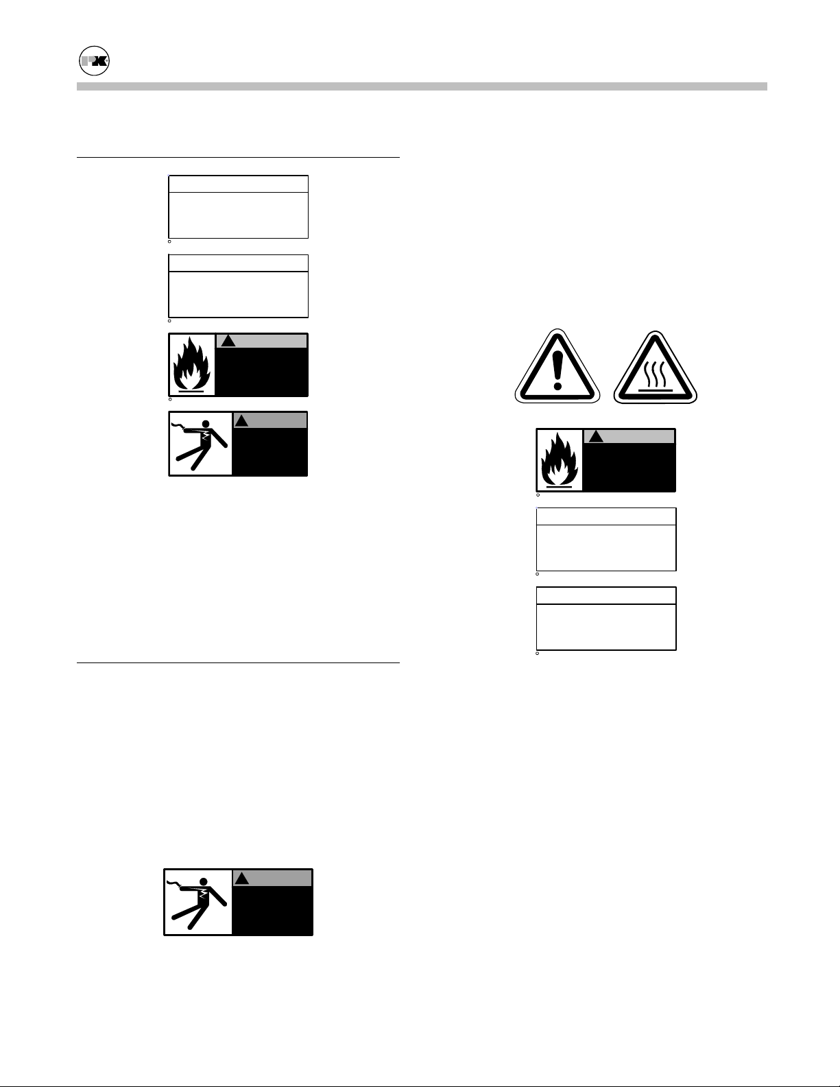
The safety labels shown above are affixed to your
boiler. Although the labels are of high quality, they
may become dislodged or unreadable over time.
Contact Patterson-Kelley for replacement labels.
2.5
SAFETY PRECAUTIONS
Provide a suitable location for the boiler, away from
normal personnel traffic, with adequate working
space, adequate clearances, proper ventilation and
lighting, with a structure sufficiently strong and
rigid to support the weight of the boiler, all piping,
and accessories.
2.5.1 Electrical Hazards
!
WARNING
Electrical hazard.
Follow lockout/tagout
procedure when
servicing this boiler.
C 1998 HCS, Inc. 800-748-0241
Reorder No. 5025-V1WHPK
2.5.2 Burn, Fire, and Explosion Hazards
General Warning
c
1998 HCS, Inc. 800-748-0241
!
Improper use may
result in fire or injury.
Read instructions/safety
manual before installing,
operating or servicing boiler.
Hot Surface
WARNING
Reorder No. 6020-V2WHPK
NOTE
Make sure this union is
tight before closing cabinet
cover after servicing boiler.
c
1998 HCS, Inc. 800-748-0241
Reorder No. 8032-02NHAK
NOTE
When opening leak test valves,
always follow instructions in
operation and safety manual.
c
1998 HCS, Inc. 800-748-0241
• Burn, fire, and explosion hazards! Installation
must be in strict conformance to all applicable
codes and standards including NFPA 54, ANSI
Z223.1 and CAN/CGA B.149. Install all required ventlines for gas devices. Refer to Section 3.7.2.
• Hazard from incorrect fuels! Possible fire, ex-
plosion, overheating, and damage. Do not use
any fuels except the design fuel for the unit.
• Overfire hazards! High pressure in gas or pro-
pane supply could result in overfiring of other
devices supplied from the same source.
• Fire and explosion hazards! Close the main gas
shutoff before servicing boiler.
Reorder No. 8032-01NHPK
2
Page 6
Modu-Fire® Gas-Fired Boiler Safety
• Fire and explosion hazards! Do not store or use
gasoline or other flammable vapors or liquids in
the vicinity of this or any other gas fired appliance.
• Burn hazard! Possible hot surfaces. Do not
touch gas vent during firing operation. Use only
factory recommended vent components.
• Burn hazard! Hot fluids. Use caution when
servicing or draining boiler.
• Fire and explosion hazards! Use caution when
servicing burner. Propane (LPG) is heavier than
air and may linger in the combustion chamber,
vent lines, or elsewhere.
• Gas leak hazard! Make sure all connections to
main burner are tight when reassembling the
burner. These connections cannot be tested after the burner is assembled.
• Gas leak hazard! All threaded gas connections
must be made using a pipe compound that is resistant to liquefied petroleum. Do not use Teflon™ tape on threaded gas piping.
• Gas leak hazard! Check entire gas train for
leaks after installation. If there is a smell of gas,
shut down the boiler and obtain immediate assistance from factory-trained personnel and/or
your local fire department.
2.5.3 Crush Hazards
General Warning
• Lifting hazards! Use properly rated lifting
equipment to lift and position the boiler. The
load is unbalanced. Test balance before lifting 3
ft. above the floor. Do not allow personnel beneath the lifted load. Refer to approximate
weights in the table below:
Boiler Size Weight in Pounds
1,000,000 Btu 595
1,500,000 Btu 990
2,000,000 Btu 1,025
• Bump hazard from overhead piping. Install pip-
ing with adequate vertical clearance.
2.5.4 Chemical Hazards
• Overfire hazard! Possible fire and explosion
from excess gas pressure. Make sure that gas
inlet pressure does not exceed 14 inches w.c. to
the regulator.
• Overfire hazard! Possible fire and explosion.
Possible malfunction of regulators and/or motorized gas valves. Maintain all gas train components in good condition. Do not alter wiring
connections. Annual inspection by factorytrained personnel for proper set-up and operation is recommended.
• Environmental hazard! The motorized gas
valves may contain hydraulic oil. Use safe procedures for the disposal of all lubricants.
• Chemical hazards from cleaning products. Use
caution when cleaning the system. The use of
professional assistance is recommended. Use
safe procedures for the disposal of all cleaning
solutions.
General Warning
• Overfire and underfire hazards! Possible fire,
explosion, overheating, and component failure.
Do not attempt to adjust firing rate of the boiler.
The firing rate must be adjusted only by factory-trained personnel.
3
Page 7
Modu-Fire® Gas-Fired Boiler Safety
2.5.5 Pressure Hazards
!
WARNING
Improper use may
result in fire or injury.
Read instructions/safety
manual before installing,
c
1998 HCS, Inc. 800-748-0241
operating or servicing boiler.
• Pressure hazard! Hot fluids. Install isolation
valves on boiler water inlet and outlet. Make
sure isolation valves are closed before servicing
boiler.
• Pressure hazard! Hot fluids. Annually test
safety relief valve for proper operation. Do not
operate boiler with faulty relief valve.
2.5.6 Slip, Fall Hazards
!
WARNING
Improper use may
result in fire or injury.
Read instructions/safety
manual before installing,
c
1998 HCS, Inc. 800-748-0241
operating or servicing boiler.
• Tripping hazard! Do not install piping on floor
surfaces. Maintain clear path around boiler.
• Slip and fall hazard! Use drip pan to catch wa-
ter while draining the boiler. Maintain dry floor
surfaces.
• Slip and fall hazard! Do not locate intake or
exhaust terminations directly above a walkway;
dripping of condensation can cause icing of the
walking surface.
4
Page 8

Modu-Fire® Gas-Fired Boiler Installation
3.0 INSTALLATION
RECEIVING AND STORAGE
3.1
3.1.1 Initial Inspection
Upon receiving the boiler, inspect it for signs of shipping damage. Pay particular attention to the control
panel on the top of the boiler and the components
mounted on the back, which may show damage from
mishandling.
The exterior cabinet must be reasonably air-tight for
the burner to operate correctly. Leaks caused by dents
in the sheet metal or panels out of position may cause
the limit controls to show Low Air. Check to be sure
that the mixer core in the top burner is centered and
has not moved in shipment; (see Section 5.2, "Cleaning the Burner" for proper location). Verify that the
total number of pieces shown on the packing slip
agrees with those actually received.
Important: Note any damage or shortage on the
freight bill and immediately notify the carrier. File
all claims for shortage or damage with the carrier
3.1.2 Storage Prior to Installation
If the boiler is not installed immediately, it must be
stored in a location adequately protected from the
weather, preferably indoors. If this is not possible,
then it should remain in the shipping container and be
covered by a tarpaulin or other waterproof covering.
Note: Controls and other equipment that are damaged
or fail due to weather exposure are not covered by
warranty.
.
temperature. Other codes or approvals which apply
will be labeled on the boiler.
Installation of the boiler must conform to all the requirements of all national, state and local codes established by the authorities having jurisdiction or, in the
absence of such requirements, in the U.S. to the National Fuel Gas Code, ANSI Z223.1/NFPA 54, latest
edition. In Canada, the equipment shall be installed in
accordance with the current Installation Code for Gas
Burning Appliances and Equipment, CAN/CGAB.149, and applicable Provincial Regulations for the
class, which should be carefully followed in all cases.
Authorities having jurisdiction should be consulted
before installations are made.
Where required by local codes, the installation must
conform to American Society of Mechanical Engineers Safety Code for Controls and Safety Devices for
Automatically Fired Boilers (ASME CSD-1).
In the Commonwealth of Massachusetts (a) this unit
must be installed by a licensed pipe fitter / plumber,
(b) field installed gas cocks must be "T" handle type,
and (c) piping of condensate shall conform with the
State Plumbing Code.
3.3
SETUP
3.3.1 Foundation
Provide a firm, level foundation, preferably of concrete.
Note: The boiler may be installed on a combustible
floor; however, the boiler must never be installed on
carpeting.
COMPLIANCE WITH CODES
3.2
The P-K MODU-FIRE® Boiler with standard components and many options complies with American National Standard/CSA Standard ANSI Z21.13/CSA 4.9,
latest edition, Gas-Fired Low Pressure Steam and Hot
Water Boilers. The heat exchanger is constructed and
stamped in accordance with ASME Boiler and Pressure Vessel Code, Section IV for 160 psig maximum
3.3.2 Placement
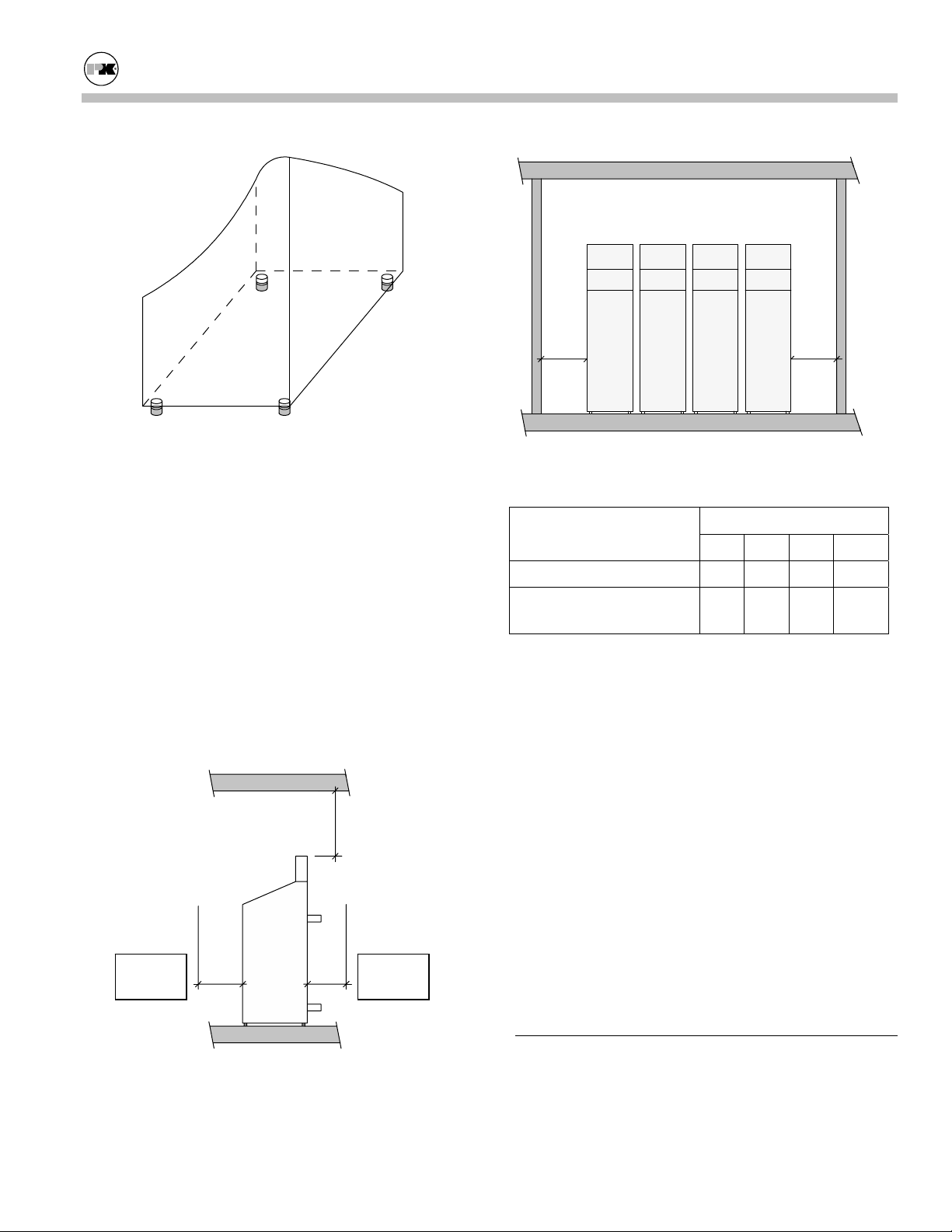
The boiler must be level to function properly. To assist in leveling the boiler, the four (4) leg bolts (1/2"NC) holding the boiler to the shipping skid must be
reinstalled in the threaded legs on the bottom. The
adjustable legs are also necessary to provide adequate
floor clearance and prevent distortion on the cabinet,
(twisting, etc.) in addition to leveling.
operating pressure and/or 250º F maximum operating
5
Page 9
Modu-Fire® Gas-Fired Boiler Installation
DD
Adjustable Legs for Leveling and Floor Clearance
3.3.3 Clearances
If the boiler is to be installed near combustible surfaces, the minimum clearances shown in the table below must be maintained.
Failure to provide for the service access clearances,
even with non-combustible surfaces, may cause future
problems servicing the boiler.
The boiler must be installed in a space large in comparison to the boiler as described in Section 6.3 of the
National Fuel Gas Code, ANSI Z223.1, latest edition.
Minimum Clearances from Adjacent Walls, Ceiling, and
Type of Surface
Combustible Surfaces 30 24 30 24
Non-combustible Sur-
faces
† "C" dimension includes clearance to remove the
burner. Do not put pipes, ducts, etc. in this area above
the boiler.
* CSA minimum. Actual clearance depends upon
stacking requirements.
Obstructions
Dimensions (inches)
A B C† D
30 24* 30 24**
** Service access need be only on one side of a boiler
No pipes,
ducts, etc.
in this area.
C
or row of boilers. Boilers may be installed immediately adjacent to each other. However, P-K recommends this clearance between each boiler when there
is insufficient access at the rear to allow for service
and adjustment.
In Canada: The boilers are approved for installation
with zero clearance to combustible surfaces, but 24
Front of
Boiler
AB
Back of
Boiler
inch service clearances are recommended.
3.4
ELECTRICAL CONNECTIONS
All field wiring connections for power and control are
in the rear service panel on the back of the boiler.
Low voltage and high voltage terminal strips are indicated on the wiring diagram. The boiler power circuit
6
Page 10

Modu-Fire® Gas-Fired Boiler Installation
is wired for 120 volts, single phase, 60 hertz. The total
operating amperage is indicated on the rating nameplate. The 1000 series require less than 9 amps; the
1500 and 2000 series less than 12 amps. Before starting the boiler, check to ensure that the proper voltage
and amperage are connected to the boiler.
An external electrical disconnect (not supplied with
the boiler) with adequate overload protection is required. The boiler must be grounded in accordance
with local codes or in the absence of such requirements, in the U.S. with National Electrical Codes,
ANSI/NFPA No. 70 latest edition and in Canada, wire
according to the current Canadian Electrical Code.
Note: A dedicated earth ground (green wire) is required to avoid nuisance shutdowns. Do not ground
through the conduit. It is also important that proper
polarity be maintained.
3.5
COMBUSTION AIR
Combustion air must be free from dust, lint, etc. The
presence of such materials in the air supplied to the
burner could cause nuisance "Low Air" shutdowns or
premature burner failure. The boiler should not be
operated during construction while the possibility of
drywall dust, demolition dust, etc. exists.
Provisions for combustion and ventilation air must be
in accordance with Section 5.3, Air for Combustion
and Ventilation, of the National Fuel Gas Code, ANSI
Z223.1, latest edition, or applicable provisions of the
local building codes. In Canada, combustion air openings shall comply with CSA 4.9. The formula is "1 sq.
in. per 1,000 Btu/hr of gas input not less than 100 sq.
in." The location shall be "neither more than 18," nor
less than 6" above the floor level."
The boiler room shall be provided with two openings
to ensure adequate combustion air and proper ventilation. One opening should be 6 to 12 inches above the
floor and the other 6 to 12 inches below the ceiling,
preferably on opposite walls. The size of each opening is determined by whether air is taken from inside
or outside the building. In Canada, ventilation air
openings shall be at least 10% of the cross sectional
area required for combustion air, but not less than 10
square inches. It is to be located at the highest practical point communicating with outdoors.
If air is taken directly from outside the building, each
opening should have a net free area of 1 square inch
for each 4,000 Btu per hour of total boiler input. For
instance, 300 square inches (2-1/12 square feet) are
required for 1,200,000 Btu per hour input.
When air is taken from the outdoors through a vertical
duct, 1 square inch per 4,000 Btu per hour is required.
If a horizontal duct is used, 1 square inch per 2,000
Btu per hour is required, i.e., 600 square inches for
1,200,000 Btu per hour input.
If air is taken from another interior space, each opening should have a net free area of 1 square inch for
each 1,000 Btu per hour of boiler input (1,200 square
inches for a 1,200,000 Btu per hour.)
WARNING!
Under no circumstances shall the boiler room ever be
under a negative pressure. Particular care should be
taken when exhaust fans, compressors, air-handling
units or other equipment may rob air from the boiler.
The combustion air supply must be completely free of
chemical fumes which may be corrosive when burned
in the boiler. Common chemicals which must be
avoided are fluorocarbons and other halogenated compounds, most commonly present as refrigerants or solvents, such as freon, trichlorethylene, perchlorethylene, chlorine, etc. These chemicals, when burned,
form acids which quickly attack the boiler tubes, tube
sheets, flue collectors and the boiler stack. The result
is improper combustion and premature boiler failure.
3.6 FLUE VENTING
This boiler requires a special vent system. Vent installations shall be in accordance with Part 7, Venting of
Equipment, of the National Fuel Gas Code, ANSI
Z223.1, CSA B149 code or applicable provisions of
the local building codes.
This boiler is Category II as it is defined in ANSI
Z21.13/CSA 4.9 latest edition. The vent material must
be listed Category II Vent pipe (316L or AL-29 4C
Stainless). Under no circumstances shall a Category I
material (e.g. B-vent) be used.
7
Page 11
Modu-Fire® Gas-Fired Boiler Installation
WARNING!
This boiler should not be installed with an automatic
damper on the flue. Damper failure could create an
explosion hazard.
In Canada, the boiler is certified for installation with a
“Power Venter” by the Canadian Gas Association
when installed with the “listed accessories.” Consult
your local distributor for information on proper selection.
The venting system and the horizontal portions of the
venting system shall be supported to prevent sagging.
Consult your local vent supplier for correct vent sizing
and structural support requirements. Vent diameter is
dictated by the length and height of horizontal and vertical portions of the vent installation and the materials
of construction. It is not necessarily the same size as
the boiler connection. Correct sizing should be based
on High fire input at a nominal -.04" w.c. draft pressure at the boiler outlet with a gross stack temp of 325º
F and CO
ratings at 7.5%.
2
3.6.1 Vent Elbows
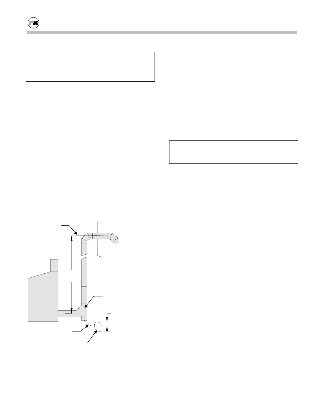
Pitch toward
boiler 1/4" per
foot minimum.
6' min.
tee. The condensate drain must be routed to a sewer
drain trap or pump in accordance with local codes.
Refer to diagram under Vent Elbows.
3.6.2 Barometric Damper
This boiler is certified for operation without a barometric damper. P-K does not recommend the use of
one.
3.6.3 Automatic Vent Damper
WARNING!
This equipment, as manufactured, MUST NOT be
used with an automatic vent damper.
3.6.4 Flue Connection
The connection from the boiler to the vent should be
as direct as possible and the upward slope of any horizontal breaching should be at least 1/4 inch per linear
foot. This boiler should not be connected into any portion of a mechanical draft system operating under
positive pressure. Provisions must be made for supports to prevent contact of the vent with combustible
surfaces.
Note: Make sure that the weight of the vent is not
supported by the boiler vent collar. The collar is not
designed to support the weight of the vent. Structural
support and spacing from combustible surfaces must
be in accordance with the vent manufacturer's requirements.
Boot Tee /135º
Tee
Trap Loop
3" min.
3.6.5 Vent Termination
The minimum vent height above the flue outlet must
be five (5) feet and the vent should extend at least
three (3) feet above the roof / snowline, or at least two
(2) feet above the highest part of any structure within
Condensate Line
To sewer trap or
condensate drain.
ten (10) feet of the vent.
The first turn from horizontal to vertical should be
made with a 135° boot tee. A tee cover with a condensate drain shall be provided at the bottom of the boot
8
Page 12

Modu-Fire® Gas-Fired Boiler Installation
(
)
4. Place the appliance being inspected in operation.
Follow the lighting instructions. Adjust the thermostat so that the appliance will operate continuously.
5. Test for spillage at the draft hood relief opening
Correct Listed
Termination
Incorrect
Termination
too restrictive
Vent Termination
The vent must be provided with a weather cap of approved design and adequate capacity.
3.6.6 Removing an Existing Boiler
(from a common venting system)
When an existing boiler is removed from a common
venting system, the common venting system is likely
to be too large for proper venting of the appliances
remaining connected to it.
At the time of removal of an existing boiler, while the
other appliances remaining connected to the common
venting system are not in operation, the following
steps should be followed with each appliance remaining connected to the common venting system placed in
operation:
after 5 minutes of main burner operation. Use the
flame of a match or candle or smoke from a cigarette, cigar or pipe.
6. After it has been determined that each appliance
remaining connected to the common venting system properly vents when tested as outlined above,
return doors, windows, exhaust fans, fireplace
dampers, and any other gas-burning appliance to
their previous conditions of use.
Any improper operation of the common venting system should be corrected so the installation conforms
with the National Fuel Gas Code, ANSI Z223.1.
When resizing any portion of the common venting system, the common venting system should be resized to
approach the minimum size as determined using the
appropriate tables in Part II in the National Fuel Gas
Code, ANSI Z223.1.
3.7
GAS PIPING
Before making the gas hook-up, make sure the boiler
is being supplied with the type of fuel shown on the
boiler nameplate.
1. Seal any unused openings in the common venting
system.
2. Visually inspect the venting system for proper size
and horizontal pitch and determine that there is no
blockage or restriction, leakage, corrosion or other
deficiency which could cause an unsafe condition.
3. Insofar as is practical, close all building doors and
windows and all doors between the space in which
the appliances remaining connected to the common venting system are located and other spaces
of the building. Turn on clothes dryers and any
appliances not connected to the common venting
The boiler shall be installed such that the gas ignition
system components are protected from water (dripping, spraying, rain, etc.) during appliance operation
and service (circulator replacement, control replacement, etc.)
The gas train components are designed to handle a
maximum inlet pressure of 14 inches water column
(1/2 psig.). If the available gas pressure exceeds 14
inch w.c., a suitable additional intermediate gas pressure regulator of the "lock up" type must be provided
to reduce the pressure to less than 14 inch w.c.
system. Turn on any exhaust fans, such as range
hoods and bathroom exhausts, so they will operate
at maximum speed. Do not operate a summer exhaust fan. Close fireplace dampers.
9
Page 13
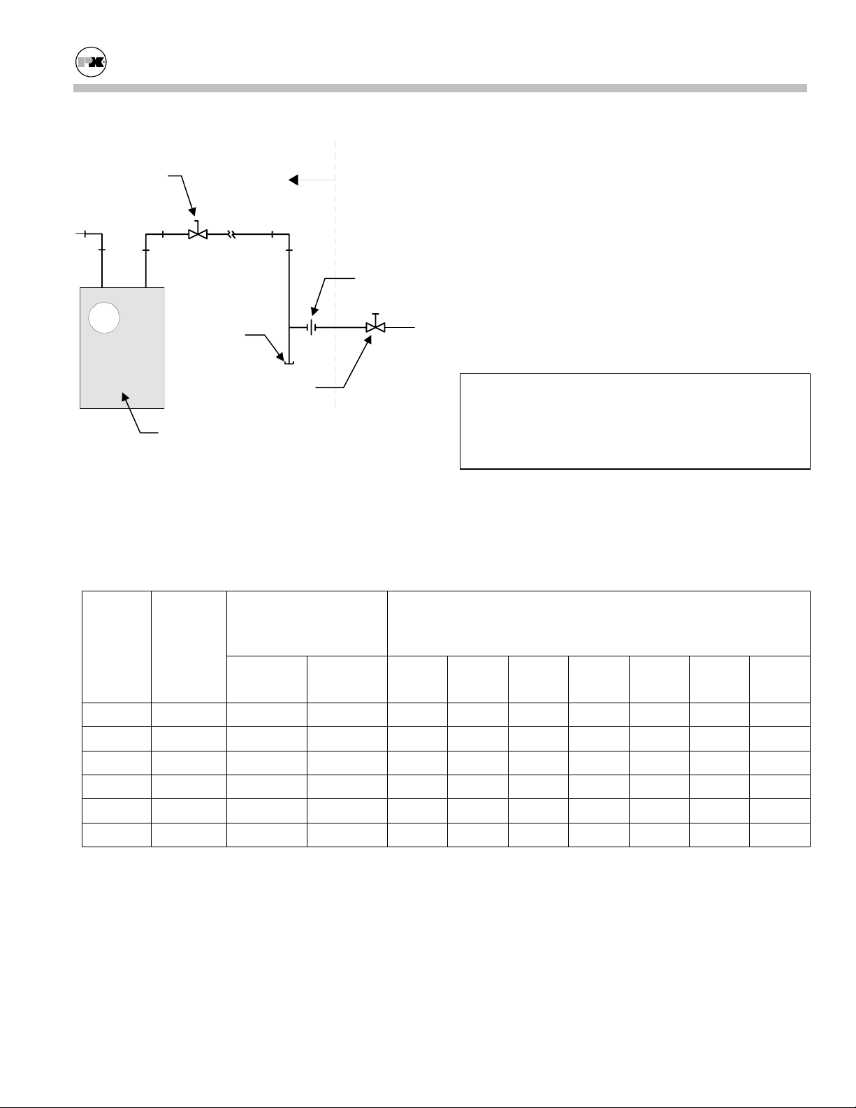
Modu-Fire® Gas-Fired Boiler Installation
Remote Gas
Shutoff (not
supplied)
Drip Leg
Gas Meter (not
supplied)
By Installer
Union
Shutoff (on
boiler)
Gas Piping
Note: Install a sediment trap (drip leg) and a union
connection ahead of the primary manual shutoff valve
Pipe Capacity for Natural Gas
Nominal
Iron
Pipe
Size
(Inches)
Internal
Diameter
(Inches)
Equivalent Pipe Length Maximum Capacity in Cubic Feet of Natural Gas per Hour
90º Ell
(Feet)
Tee
(Feet)
on the boiler. Gas piping should be installed in accordance with National Fuel Gas Code, ANSI Z223.1,
latest edition, and any other local codes which may
apply; in Canada see CAN/CGA-B 149.
Note: See chart below for required pipe size, based on
overall length of pipe from meter plus equivalent
length of all fittings. Approximate sizing may be based
on 1 cubic foot of natural gas per 1,000 Btu per hour
input, i.e., 900,000 Btu per hour requires about 900
cubic feet per hour. (See Typical Boiler Operating
Conditions, Section 4.3, for more information.)
WARNING!
All threaded connections must be made using a pipe
compound that is resistant to the action of liquefied
petroleum gases. Do not use Teflon tape on gas line
threads.
Pressure Drop of 0.5 inch Water Column/Equivalent Length of
Pipe (in feet)
20
40
60
80
100
150
200
1-1/4 1.380 3.45 6.9 950
1-1/2 1.610 4.02 8.04 1,460 990 810
2 2.067 5.17 10.3 2,750 1,900 1,520 1,300 1,150 950 800
2-1/2 2.469 6.16 12.3 4,350 3,000 2,400 2,050 1,850 1,500 1,280
3 3.068 7.67 15.3 7,700 5,300 4,300 3,700 3,250 2,650 2,280
4 4.026 10.1 20.2 15,800 10,900 8,800 7,500 6,700 5,500 4,600
10
Page 14

Modu-Fire® Gas-Fired Boiler Installation
3.7.1 Gas Supply Piping by Installer
The boiler and all gas piping connections should be
pressure-tested and must be checked for leaks before being placed into service. Test with compressed air or inert gas if possible.
The boiler must be disconnected at the boiler manual shut-off valve (located at the end of the supplied
gas train) from the gas supply piping system during
any pressure testing of the system at pressures in
excess of 1/2 psig (14 inch w.c.).
During any pressure testing of the gas supply piping
system at pressures equal to or less than 1/2 psig (14
inch w.c.), the boiler should be isolated from the gas
supply piping system by closing the manual shutoff.
Some leak test solutions, including soap and water,
may cause corrosion. These solutions should be
rinsed-off with water after testing.
3.7.2 Gas Bleeds and Vents by Installer
If your unit is equipped with a diaphragm gas valve,
the bleed vents on the diaphragm gas valves have
been factory-piped to terminate at the burner, as required by ANSI Z21.13. This feature provides combustion of any gas which leaks past a ruptured diaphragm during operation. Gas vents to outdoor air
must be provided for the main pressure regulator.
The pilot regulator is equipped with a vent limiting
device and does not require external venting!
• When installing per ASME CSD-1, discon-
nect factory piped bleed vents and vent the
diaphragm gas valves to outdoor air (field
piping.)
If a N.O. (normally open) vent valve is provided, it
must be vented independently of any other bleeds
and vents. Discharge of vent lines should be protected by an insect screen.
The air gas ratio control valve is equipped with a
“reference chamber vent filter” which does not require any additional venting. This connection is
labeled COMBUSTION / ATMOSPHERE.
If local conditions require venting to outdoors, the
vent line connection must be piped by the installer
in accordance with the National Fuel Gas Code
(NFPA 54), ANSI Z223.1, which states:
“In the case of vents leading outdoors, means shall
be employed to prevent water from entering this
piping and also to prevent blockage of vents by insects and foreign matter.”
The National Fuel Gas Code Handbook goes on to
say that “Insects, insect nests, ice, or freezing rain
can block outdoor vents....”
The pilot regulator is equipped with a vent limiting
device and does not require external venting!
Gas Vents by Installer
Note: Provide a drip leg in all vent/bleed lines.
All vent lines should be pitched up at all times to
prevent building a trap into the vent line.
“Vent limiters” are NOT to be installed on this
boiler.
The air gas ratio control valve is equipped with a
“reference chamber vent filter” which does not require any additional venting.
3.8
BOILER WATER PIPING
3.8.1 Piping Design
Water Flow in System
Ideal operation of the P-K MODU-FIRE® Boiler
would consist of a 20º F temperature differential
across the heat exchanger at High fire. Insufficient
flow may result in excessive short cycling of the
boiler and eventual damage or premature failure of
the equipment.
Minimum Return Water Temperature should be
greater than 130º F to avoid problems of condensation on the outside of the heat exchanger or in the
flue passages.
Proper flow rates and return water temperature may
be achieved through a combination of primary and
secondary flow loops. Multiple zones and pumps
may result in different flow rates at different times.
11
Page 15
Modu-Fire® Gas-Fired Boiler Installation
Consideration must be given to all possible conditions and their consequences.
Piping With Refrigeration Machines
When used with a refrigeration system, the boiler
shall be installed so that chilled medium is piped in
parallel with the boiler. Valves should be installed
to prevent chilled water from entering the boiler
when the system is operated in the cooling mode.
Piping With Air Handling Units
The boiler piping system of a hot water heating
boiler connected to heating coils located in air handling units, where they may be exposed to refrigerated air circulation, must be equipped with flow
control valves or other automatic means to prevent
gravity circulation of the boiler water during the
cooling cycle.
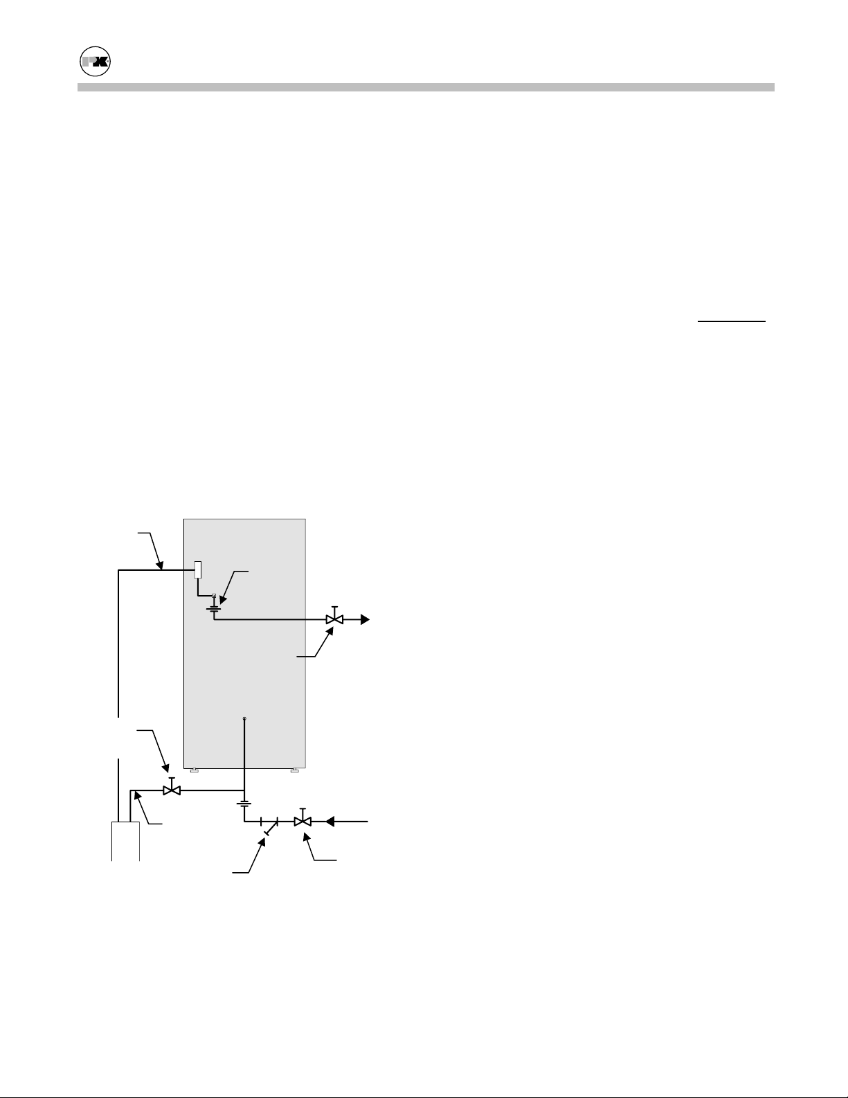
3.8.2 Boiler Inlet and Outlet Connections
Relief Valve
Drain
Union
Outlet (to
system)
Note: Pipe unions and isolating valves must be
installed in both water connections for ease of
service.
The bottom connection to the boiler is the INLET
and must be used for the return from the system.
The top connection to the boiler is the OUTLET and
must be connected as the supply to the system.
Piping must be installed such that no piping stresses
are transmitted to the boiler. The boiler should not
be used as a pipe anchor.
3.8.3 Boiler Water Piping by Installer
Strainer
To avoid possible contamination of the boiler with
dirt, rust or sediment from the system, a strainer
near the boiler inlet is strongly recommended. Even
new systems may contain sufficient foreign material
to eventually reduce the performance of the heat
exchanger. Adequate circulation of good clean water is essential to maximum efficiency and long life
of the boiler.
Relief Valve and Piping
Isolating
Valve
Isolating
Valve
Inlet (from
Boiler
Drain
Strainer
Boiler Inlet and Outlet Connections
system)
Isolating
Valve
Make water connections as the application warrants,
or at a minimum, as shown, but always in compliance with the local requirements.
Each boiler is supplied with a pressure-relief valve
sized in accordance with ASME requirements. The
relief valve should be piped to a suitable floor drain.
Reducing couplings or other restrictions are not
permitted in the discharge line.
Low Water Cut-off
The boiler is furnished with a flow-switch-type low
water cut-off as required by Section IV ASME
Code; no field piping is required. If the flow switch
does not sense water flow, the boiler will shut down
and a red indicator will be illuminated on the control
panel. This flow switch only proves that flow is
present. It does not prove adequate flow as required
by this boiler.
Installation of an external low water cutoff or manual reset low-water switch may be required by certain codes or in certain installations. Consult your
local code for details.
12
Page 16

Modu-Fire® Gas-Fired Boiler Installation
WARNING!
Never install a valve that can isolate the low water
cutoff from the boiler.
Drain Valve and Piping
The boiler is not provided with external drain connections. A drain valve should be installed near the
inlet (system return) connection to the boiler and
piped to a suitable floor drain. The boiler can be
completely drained through the bottom header by
removing the flush plug in the bottom end plate.
This plug may also be used to flush accumulated
sediment from the bottom of the boiler.
3.8.4 Flushing and Filling
Flushing the System
Before filling the boiler, flush the system to remove
the debris. Clean and flush old piping thoroughly
before installing the boiler as recommended by your
water conditioning or chemical treatment supplier.
Under no circumstances should the hydronic system
be flushed while the boiler is attached to the system
since the debris or corrosion products could accumulate in the boiler and plug the boiler heat exchanger.
If the piping system attached to this unit will be
chemically cleaned, the boiler must be disconnected
from the system and a bypass installed so that the
chemical cleaning solution does not circulate
through the boiler.
Filling
To be sure that the boiler is not air-bound, open the
pressure-relief valve located at the rear of the boiler.
Leave the relief valve open until a steady flow of
water is observed. Close the valve and finish filling
the system.
treated make-up water can cause premature failure
due to buildup of scale. Such failure is not covered
by warranty.
Scale can also reduce efficiency. For example, a
scale thickness of 1/16" will result in a 12.5% loss
of efficiency.
The water quality should be within the guidelines
established by the American Boiler Manufacturers
Association, as follows:
• Total solids: 2,500 ppm
• Total alkalinity: 500 ppm
• Total hardness: 150 ppm
The amount of oils, fats, grease, and other organic
matter should be limited to 10 ppm.
Consult your water conditioning or chemical treatment supplier for analysis and recommendations.
If antifreeze is to be used in the system, the customer should perform a hazard analysis to determine
the use and disposal of the antifreeze.
3.9
BURNER AND IGNITION SYSTEM
3.9.1 Inspection
Inspect the burners to be sure nothing was damaged
or knocked loose during shipment. Make sure that
the mixer core in the top of the burner is centered in
the burner head; (see burner photo in section on
"Cleaning the Burner" Section 5.2). Inspect the pilot line, main gas train and ignition electrode to be
sure they were not damaged during shipment or installation. Check to see that the pilot is securely
attached and that it is properly positioned to ignite
the main burner.
3.10
PRE-START CHECK LIST
3.8.5 Water Quality
The boiler is designed to operate in a closed-loop
system. As such, the system should be tight and not
Before attempting to start the boiler, make sure the
following items have been completed.
1. Flue gas from the boiler is properly vented.
require make-up water. A high percentage of un-
13
Page 17
Modu-Fire® Gas-Fired Boiler Installation
2. Gas connection has been made, pressure tested
for leakage, and the line purged of air. Make
sure all required bleeds and vents have been installed.
3. Water connections are complete, and the boiler
and system have been filled and purged of air.
4. The boiler must be connected to a 120 volt / 60
Hz power source with proper polarity and dedicated machinery ground. Provide a disconnect
having adequate overload protection.
5. Combustion air openings are not obstructed in
any way and have adequate capacity. (See Section 3.5)
6. The boiler is placed the proper distance from
any combustible walls or substances, in accordance with Section 3.3.3.
7. Relief valves have been properly piped to floor
drains.
SAFETY CHECKS
3.11
The following checks of safety systems must be
made before putting the boiler into normal operation.
Before firing the boiler refer to Sections 4.1 and 4.2
for information on the use of the controls, lighting,
and shut-down procedures.
WARNING!
Never attempt to operate a boiler that has failed to
pass all the safety checks described below.
WARNING!
After checking controls by manual adjustment, make
sure they are always reset to their proper settings.
3.11.1 Test of Ignition Safety System
Test the ignition system safety shutoff as follows:
1. Close the gas cock which is downstream from
the two safety shut off valves (in the vertical
line).
2. With the main gas cock (inlet manual gas valve)
open and the pilot gas cock open, the burner
should be cycled on. After all the safety limits
on gas pressure, water flow and temperature are
satisfied, the blower will run and pre-purge the
boiler.
3. When air flow is established, the ignition transformer and pilot will operate. Both functions
will be indicated by separate indicator lights on
the flame safeguard.
4. If a satisfactory pilot is established, the spark
will terminate and the pilot will remain on,
alone, for 10 seconds.
5. After 10 seconds, the "Main” light on the flame
safeguard will go on; gas will not flow since the
downstream cock is closed. The "Pilot" will
remain on, along with the "Main Gas", for another 10 - 15 seconds and then go out. Since the
gas cock is closed, at this point there will be no
main flame signal and the flame safeguard programmer will assume a “Flame Failure” and go
to a "lockout" mode. Lockout will require manual reset of the flame safeguard.
After completing this test, turn off the boiler and
reopen the downstream gas cock.
3.11.2 Test of Low Water Cut-off
The boiler is furnished with a flow-switch-type low
water cutoff in the outlet nozzle. Test as follows:
Operation of the switch can be checked by first turning the boiler off and then turning the system pump
off, stopping water flow in the system. After turning off the pump, turn the boiler back on. It should
not operate, and a red indicator for "Low Water" or
"Water Flow" should be illuminated. Do not shut
the pump off while the boiler is operating.
Perform appropriate tests on any external probe-type
low water cutoff.
3.11.3 Test of Limit Controls
Fire the boiler and test the high limit control as follows:
With the main burner operating, turn down the temperature setting on the "high-limit" thermostat until
14
Page 18

Modu-Fire® Gas-Fired Boiler Installation
the main burner shuts off (the green "Heat" indicator
will go out). The high-limit switch must be manually reset after testing. This same check should also
be made for the "Operating Temperature" control.
After completion of these tests, readjust thermostats
to desired operating temperature and set high-limit
temperature, typically 20º F above operating temperature.
3.11.4 Test of Low Gas Pressure Switch
Manual Reset
Gas Pressure Switch
The boiler is furnished with a low gas pressure
switch. The operation of this switch must be
checked by slowly closing the main gas cock while
the burner is operating. The switch should shut
down the main burner. When the gas pressure
switch opens, the "Gas Press." indicator will light.
Upon reopening the main gas cock, the "Gas Press."
indicator should remain on until the low gas pressure switch is manually reset.
3.11.5 Test of High Gas Pressure Switch
The correct setting of the high gas pressure switch is
essential for proper operation of the boiler. This
switch is set by the factory at 4.0” w.c. and must not
be changed.
This switch must be checked by factory-trained personnel.
3.12
INITIAL ADJUSTMENTS
3.12.1A – Configuring the Local Controller
(Applies to models furnished with programmable
temperature control.)
Operating Modes:
Internal Setpoint
Night Setback (Alternate Setpoint)
Outdoor Air Reset
Analog Input Setpoint (See Section 3.12.1B.)
Analog Input Direct Drive (Multiple boiler
Controls)
Definitions:
SP1- Setpoint 1:...................This is the primary
setpoint of the boiler.
SP2- Setpoint 2 :...................An alternate setpoint.
Available through the
alternate setpoint contact closure.
dSP- Differential Setpoint : ..An alternate setpoint
differential from SP1.
Available through the
alternate setpoint contact closure.
tA- Air temperature: ............Measurement of out-
side air temperature.
SP.E- External Setpoint:.......Measurement of the
external setpoint.
HyS1:....................................Low temperature dif-
ferential.
HyS3:....................................High temperature dif-
Internal Setpoint
ferential.
The boiler water outlet temperature is controlled to
SP1 (setpoint 1) and the boiler modulates to maintain SP1 subject to the upper and lower temperature
differentials and the upper and lower setpoint limit.
15
Page 19

Modu-Fire® Gas-Fired Boiler Installation
For example, assume the following settings:
Item Display Value
Setpoint 1 SP1 160
Low Temp Differential HyS1 -5
High Temp Differential HyS3 12
Low Temp Setpoint SPL 150
High Temp Setpoint SPH 195
The boiler will modulate to try to maintain 160
If the temperature increases to 172
o
F which is Set-
point 1 (SP1) 160 + High Temp Differential (HyS3)
12, it will shut off. Once it shuts off, it will not restart until the temperature drops to 155
o
F which is
Setpoint 1 (SP1) 160 + Low Temp Differential
(Hys1) -5
. The Low Temp Setpoint (SPL) prevents
the operator from setting Setpoint 1 (SP1) lower
than Low Temp Setpoint (SPL) 150. The High
Temp Setpoint (SPH) prevents the operator from
setting Setpoint 1 (SP1) higher than the High Temp
Setpoint (SPH) 195.
Alternate Setpoint
The control must be configured for night setback.
(See the configuration menu.) When the Alternate
Setpoint contact is closed the boiler switches to its
alternate setpoint.
The alternate setpoint can be determined by several
different values. It can be a fixed alternate setpoint
SP2. It can be a fixed differential from SP1 called
dsP. dsP will “offset” the main setpoint SP1 by the
value of dsP. dsP can be positive or negative.
The Alternate Setpoint can also be determined by an
external analog source such as a 4-20 mA signal.
Outdoor Air Reset
The control must be configured for outdoor air reset.
(See the configuration menu.)
o
F.
The setpoint of the boiler is controlled by an outdoor temperature sensor. As the outdoor temperature falls the setpoint of the boiler is increased.
The boiler modulates to maintain this setpoint. The
boiler functions as indicated in internal setpoint;
however, SP1 is determined by the outdoor air temperature.
The setpoint SP1 is reset using a linear relationship
with outdoor air temperature. As the outdoor air
temperature drops the setpoint SP1 is increased a
proportional amount. This increase is determined
by the Heating Slope H. (See Table 1 at the end of
this section.) For example if H is set at 1 then for
every degree the outdoor air temp drops, the setpoint SP1 will increase 1 degree.
This heating curve has a reference temperature of
68°. This reference can be offset using the Parallel
shift parameter P. (See Table 1 at the end of this
section.) If P is set to 0 the setpoint SP1 will be 68°
when the outdoor temp is 68°. If P is set to 10, the
setpoint SP1 will be 78° when the outdoor temp is
68°. The minimum setpoint of the boiler is limited
by the control. In the above example the actual setpoint SP1 of the boiler will not go below 150°.
Analog Input Setpoint
The control must be configured for external setpoint. (See the configuration menu.)
The setpoint of the boiler is controlled by an external signal. The boiler functions as described with
the internal setpoint, using the value determined by
the external analog signal.
16
Page 20

Modu-Fire® Gas-Fired Boiler Installation
Analog Input Direct Drive
The firing rate of the boiler is controlled by an external analog signal, usually from a multiple boiler
control. The boiler turns on and off as directed by
the external control.
An operating limit control ensures that the boiler
temperature does not exceed the set value.
Refer also to Section 3.12.1B.
Use of the Controller
Actual Value
Display (red)
Setpoint
Display
(green)
Operating Limit Closed
Firing Rate Decreasing
Firing Rate Increasing
Manual Operation
Alarm Relay
Energized
PARAMETER level, and the
CONFIGURATION level.
The following table indicates the menu options
available from each level. The options available
depend on the operating mode of the boiler.
Decrease
Value
PROGRAM
Button
Increase
Value
EXIT Button
The diagram shows the RWF40 after switching on
power. This condition is called the basic display.
The actual value and the currently active setpoint
are shown here. Manual operation, self-setting, and
the user, parameter, and configuration levels can be
activated from here.
Operation of the Control
The temperature control has three levels of cascading menus. They are:
USER level,
User Level:
To access the User level from the basic display
press PGM.
Change the setpoint SP1 with or .
Change to setpoint SP2 or dSP with PGM.
Change the setpoint SP2 or dSP with or .
Return to the basic display with EXIT.
Manual Operation of the Boiler
The boiler firing rate can be controlled manually.
17
Page 21

Modu-Fire® Gas-Fired Boiler Installation
To change to manual operation press EXIT for
5 seconds.
The LED above the hand symbol lights up.
Change the firing rate of the boiler with or
.
The firing rate increases as long as is pressed.
The firing rate decreases as long as is
pressed.
LED's on the control indicate if the firing rate is
increasing or decreasing.
To change back to automatic operation press
EXIT for 5 seconds.
Manual operation can only be activated if the burner
relay is on. If the control sets the burner relay to off
during manual operation, then the control is changed
to automatic operation.
Parameter Level
To access the parameter level press and hold the
PGM button for longer than two (2) seconds. The
parameters available in this level are used for proper
functioning of the boiler with the system.
Within the parameter level you can go to the next
parameter by pressing PGM.
The parameters and their functions are listed in Table 1 on the following page. The actual parameters
available depend on the configuration of the control.
18
Page 22

Modu-Fire® Gas-Fired Boiler Installation
Table 1 - Table of Parameters
19
Page 23
Modu-Fire® Gas-Fired Boiler Installation
Configuration Level
The configuration level is used to set up the control
for the sensors used, and the functioning of the
alarm relay. The configuration level must be adjusted by factory-trained personnel only.
3.12.1B Optional Remote Control
This option is used when the firing rate of the boiler
is controlled by an external analog signal, usually
from a multiple boiler control. The boiler turns on
and off as directed by the external control.
An operating limit control ensures that the boiler
temperature does not exceed the set value.
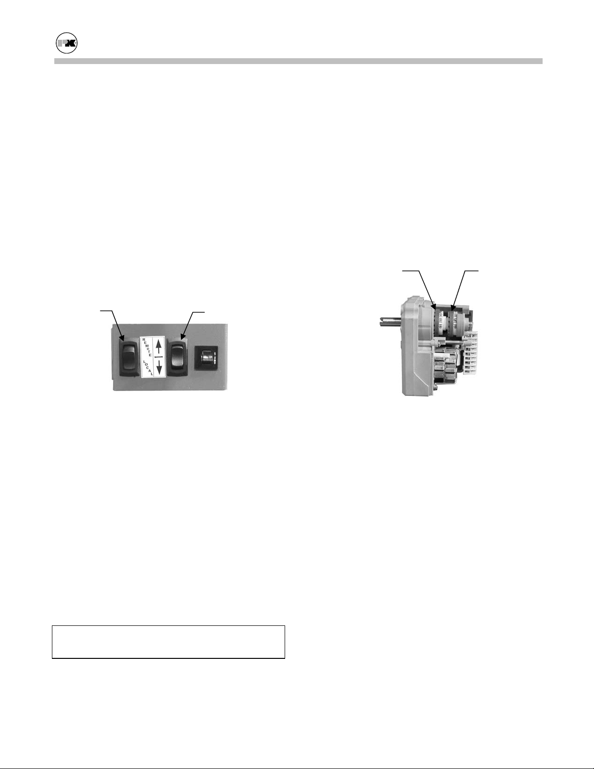
Remote/
Local
Firing Rate
3.12.2 Air Flow Adjustments
The air flow is pre-set at the factory prior to shipment. The air (and gas) may have to be adjusted for
local conditions. All air flow adjustments must be
performed by factory-trained personnel.
The air and gas are adjusted at two firing rates: High
fire and Low fire. The boiler modulates between
these two rates to maintain a steady outlet temperature.
Fuel adjustments for proper fuel/air ratio are made
first at High fire, then at Low fire.
Red Blue
Remote/Local and Firing Rate Switches
Local control is used for setting up and testing the
boiler. Local control of the boiler firing rate can be
obtained by placing the Remote/Local switch in the
local position (This does not bypass # 1 start interlock, # 1 start interlock must be made for the boiler
to fire). With the boiler in local mode, the up/down
switch can be used to control the firing rate of the
boiler. Pressing this switch in the up direction increases the firing rate. Placing this switch in the
down position decreases the firing rate.
To operate the boiler independently from the BMS
(Building Management System) or sequencer, an
external bypass switch of the BMS must be installed
by the control contractor.
WARNING!
Do not bypass any safety limits with this switch.
Air Flow Adjustments
The air flow rates are adjusted by setting the end
switches in the damper actuator. The red end switch
sets the High fire position. The blue end switch sets
the Low fire position. To set the position of the
switch, rotate the colored wheel corresponding to
either High fire or Low fire until it indicates the desired setting. Once the desired setting is set, move
the damper to a mid position and then back to either
Low or High fire as desired.
The red air flow cam should be set so that the cabinet pressure at High fire is at or below that indicated
on the rating plate for High fire. The blue cam
should be set so that the cabinet pressure at Low fire
is at or above that indicated on the rating plate for
Low fire.
The cabinet air pressure at Low fire must be at least
0.3” w.c.
20
Page 24

Modu-Fire® Gas-Fired Boiler Installation
3.12.3 Gas Pressure Adjustment
See ratin g plate for the minimum and maximum gas
pressure of the boiler. Each boiler is furnished with
two plugged taps in the gas manifold for test gauge
connections. One tap is located at the main gas
cock for measuring the gas supply pressure (1/4”
IPS). The supply pressure during main burner operation must be greater than the minimum indicated
on the rating plate. The second tap is located downstream from the last main gas control in the union
elbow where the gas line enters the back of the
cabinet and is for measuring the manifold gas pressure (1/8” I.P.S.)
Low-fire Adjustment
High fire Adjustment
Gas Pressure Adjustment
BASIC COMBUSTION ADJUSTMENT PROCEDURE
To adjust the gas pressure, remove the cover plate
from the air / gas ratio control valve. Set the boiler
at High fire as described in the boiler operation section of the manual. The High fire gas pressure is
adjusted with the lower screw of the air / gas ratio
control vale. Using a combustion analyzer, adjust
the oxygen reading between 6.5% and 7.5%. Set the
boiler at Low fire as described in the boiler operation section of the manual. For initial adjustment
the cabinet pressure should be the same as shown on
the “Factory Firetest” label. The Low fire gas pressure is adjusted with the upper screw of the air / gas
ratio control valve. Using combustion measurement
equipment, adjust the oxygen reading between 6.5%
and 7.5%.
Run the firing rate up and down through the complete firing range and verify that the oxygen readings are within the proper range.
Start boiler in test mode
Adjust start pressure with orange cam 1.0” – 1.2” H2O cabinet air
Adjust pilot gas for good pilot – See factory run out label
Start boiler and measure combustion O2 between 6.0 – 8.0
Ramp to high fire adjust cabinet air to nameplate with red cam. Combustion O2 between 7.0 – 7.5.
Ramp to low fire 0.3” adjust cabinet air with blue cam
Check high fire and low fire again
21
Page 25
Modu-Fire® Gas-Fired Boiler Operation
4.0 OPERATION
GENERAL
4.1
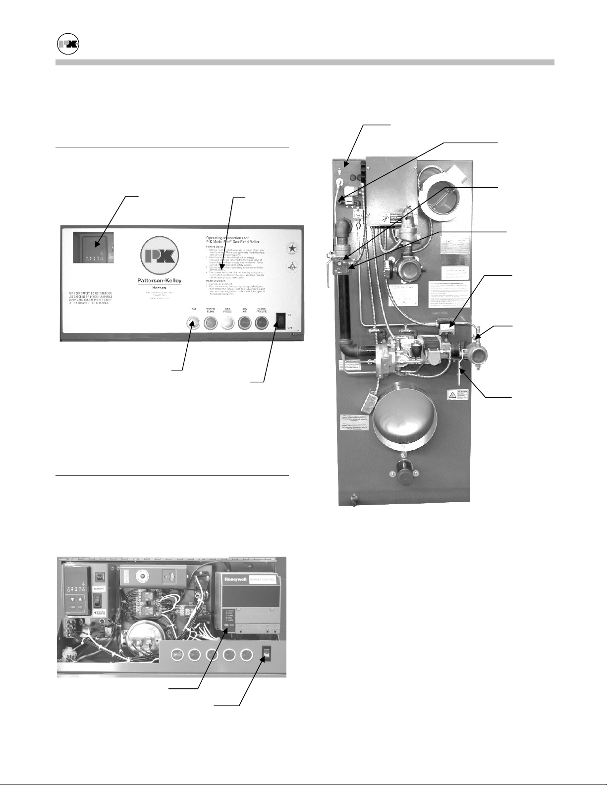
4.1.1 Control Panel Front
Temperature
Control
Operating
Instructions
Indicator Lights
On-Off Switch
The front of the control panel shows Operating Instructions and a series of illuminated indicator lights
which show the condition of the boiler.
Cabinet Air
Pressure
Test
Pilot Gas
Pressure
Test
Main Gas
Pressure
Test
High Gas
Pressure
Switch
Low Gas
Pressure
Switch
Pilot Gas
Cock
Main Gas
Cock
4.2
LIGHTING AND SHUT-DOWN PROCEDURES
Do not use this boiler if any part has been under water. Immediately call factory-trained personnel to
inspect the boiler and to replace any part of the control system and any gas control which has been under water.
Reset Switch
On-Off Switch
4.2.1 Lighting Procedures
1. Utilities: Turn on electric supply to boiler.
Open gas supply valves. Make sure system is
filled with water and turn on circulation pump.
2. Reset Switches: Press reset button on gas pressure switches (attached to main gas valve at
back of boiler) if gas supply was turned off.
Press control reset button after safety lockout.
3. Set desired limit and operating temperature (inside control panel).
22
Page 26

Modu-Fire® Gas-Fired Boiler Operation
4. Turn power switch on. If a red warning indicator is illuminated, see call for factory-trained
personnel to troubleshoot the problem and implement corrective action. Wait five minutes
before attempting to reset boiler.
4.2.2 Normal Shut Down Procedures
1. Close all manual gas valves.
2. Turn off electric power.
4.2.3 Emergency Shut Off
Main and pilot gas cocks should be closed immediately if an emergency situation occurs; see Section
4.2.1 for the location of the gas cocks.
If overheating occurs or the gas supply fails to shut
off, do not turn off or disconnect the electrical sup-
ply to the pump. Instead, shut off the gas supply at
a location external to the boiler.
TYPICAL BOILER OPERATING CONDITIONS
4.3
Natural Gas
(1030 Btu/cu. Ft.)
Gas
Rate
(CFH)
Output
Capacity
(Btu/Hr.)
Model
No.
1000
1500
2000
Input
Rating
(Btu/hr)
1,000,000 971 850,000
1,500,000 1,456 1,275,000
2,000,000 1,942 1,700,000
23
Page 27

Modu-Fire® Gas-Fired Boiler Maintenance
5.0 MAINTENANCE
General Lock out / Tag out procedure must be employed when servicing unit.
Hazard analysis should be performed by end user to
insure safety of their employees and/or service technicians.
In addition to the requirements of Section 2.1, maintenance performed on the Siemens gas valve requires that the valve be removed from the boiler and
securely placed in a vice prior to performing any
maintenance.
5.1
MAINTENANCE AND INSPECTION SCHEDULE
WARNING!
Label all wires prior to disconnection when servicing
controls. Wiring errors can cause improper and
dangerous operation.
Verify proper operation after servicing.
5.1.1 Daily
Observe operating temperature and general conditions. Make sure that the flow of combustion and
ventilating air to the boiler is not obstructed. Determine the cause of any illuminated red indicators,
unusual noises or operating conditions and make the
necessary corrections.
WARNING!
Check daily to be sure that the boiler area is free
and clear of any combustible materials, including
flammable vapors and liquids.
The motorized gas valves contain hydraulic oil
which may be hazardous to the environment.
Should a leak develop, use safe procedures for disposal of this or any other lubricant.
5.1.2 Weekly
Observe the conditions of the pilot and main flame.
A normal High fire flame is blue. If the flame is
yellow, then corrective action must be taken. In
Low fire the burner will glow a yellowish orange.
Correct air adjustment is essential to the efficient
operation of this boiler. If an adjustment in the
combustion is necessary, the flue gas composition
should be checked with a carbon dioxide (CO
oxygen (O
) analyzer to set conditions. Refer to
2
) or
2
Section 3.12.2 and 3.12.3.
5.1.3 Monthly (During Operation)
1. Test flame detection by voltage reading at the
control programmer.
2. Test high-limit control by reducing setting below the operating temperature. Burner should
shut off. After readjusting the thermostat, press
the button to reset the switch.
3. Test operating temperature controls by reducing
or increasing temperature setting as necessary to
check burner operation.
4. Check flue gas temperature at outlet. If there is
a temperature increase over previous readings,
this probably indicates sooting or water scale
build-up.
5. Test the water cutoff by trying to restart boiler
with the system pump off. The boiler should
not operate. Water flow indicator should light.
6. Test low gas pressure switch by closing main
gas cock and attempting to restart boiler.
This work should be performed by factory-trained
personnel.
5.1.4 Semi-Annually
In addition to the recommended monthly service:
1. Inspect and clean blower fan and inlet screen of
any accumulated dust or lint.
2. Clean burner of any accumulated dust or lint.
See Section 5.2 on "Cleaning the Burner."
24
Page 28

Modu-Fire® Gas-Fired Boiler Maintenance
3. Inspect burner for any signs of deterioration or
corrosion. Replace immediately if deterioration
or corrosion is evident.
The blower motor is permanently lubricated and
does not require periodic lubrication.
This work should be performed by factory-trained
personnel.
5.1.5 Annually
In addition to the recommended monthly service:
1. Check burner and clean off any soot or foreign
material that may have accumulated. See Section 5.2 on "Cleaning the Burner." Check for
corrosion of the burner and its parts. If there is
evidence of deterioration or corrosion, replace
immediately.
2. Inspect combustion chamber through access
door on front side of boiler. To remove doors,
remove fasteners, pull door forward slightly,
then pull upward. Note any signs of deterioration. Take corrective action as necessary.
3. Inspect and clean heat exchanger. Clean exterior of finned tubes and flush inside of heat exchanger as required (separate from system
flush).
4. Examine the venting system at least once a year.
a. Check all joints and pipe connections for
tightness.
b. Check pipe for corrosion or deterioration. If
any piping needs replacing, do so immediately.
5. Inspect heating system for other problems. This
work should be performed by factory-trained
personnel.
6. Perform combustion analysis.
7. The relief valve should be tested as per the
valve manufacturer’s recommendations at least
annually or as indicated by local codes.
CLEANING THE BURNER
5.2
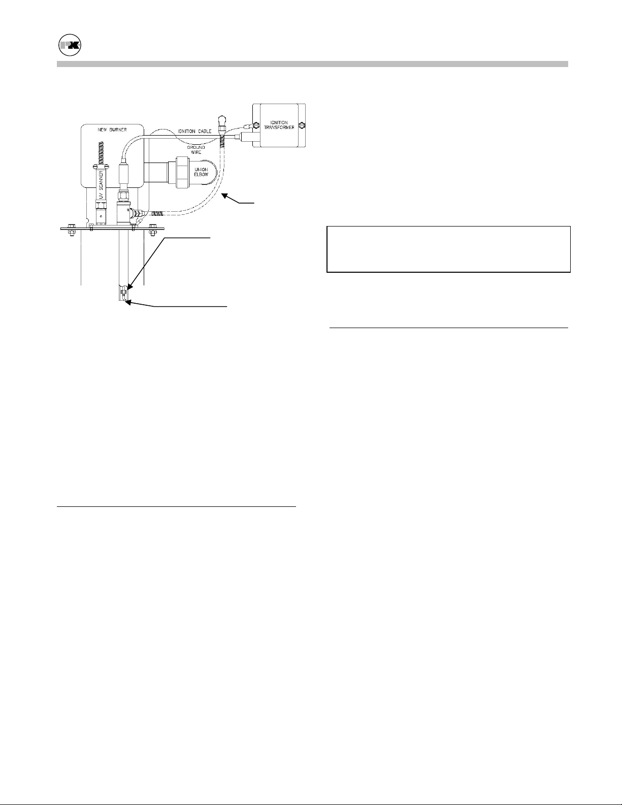
Ignition
Electrode
UV
Scanner
Burner
Burner
Screen
Mixer
Core
Pilot
Tube
Burner Assembly
1. Follow Lock out / Tag out procedures for Electric, Gas, and Water connections.
2. Remove the top cover of the boiler.
3. Disconnect the pilot tube, main gas union, electrode wire, ground wire, mixer core tube, UV
Scanner, and the 4 burner hold down nuts.
4. Remove the burner and mixer core from the
boiler and place it on the floor.
5. Use low pressure air, max. 20 psig, to blow inside the burner first, then outside of the burner,
in order to remove any accumulated dust or lint
build-up. Also blow the air down the pilot tube
to clean away any dust or dirt
6. Check that the electrode is not touching the wall
of the pilot tube. Also be sure the electrode is
not cracked and that the ceramic spider is able
to move up and down freely.
7. Use a soft, clean cloth to remove accumulated
contaminants from the UV radiation tube (UV
scanner) glass envelope.
8. Leak test gas valves.
25
Page 29
Modu-Fire® Gas-Fired Boiler Maintenance
8. Remove the nuts and bolts from the flanges of
the inlet and outlet nozzles at the rear of the
outer casing.
9. Remove the exchanger and clean the fins.
Note: The inner and outer cabinets are separate
Pilot
Tube
Ceramic Spider
parts and reassembly is easier if the inner cabinet
and exchanger are removed together as one unit.
WARNING!
The heat exchanger is heavy; use proper lifting
equipment and techniques.
Ignition
Electrode
8. Before re-installing the burner, check the
cleanliness of the heat exchanger and the condition of the combustion chamber. If corrosion or
leaks are noticed, (green or otherwise, please
call the factory for assistance)
9. Install the burner and mixer core. Reconnect
the pilot tube, main gas union, 4 burner hold
down nuts, electrode wire, ground wire, mixer
core tube, UV Scanner. Be sure the Pilot tube is
not touching any other component.
5.3
REMOVING THE EXCHANGER
1. Remove the burner as above.
2. Remove the front doors by pulling forward and
upward.
3. Remove the top panel of the inner cabinet.
5.4 AFTER ALL REPAIRS OR MAINTENANCE
1. Follow "Pre-Start Check List" (Section 3.10)
and all "Safety Checks" (Section 3.11).
2. Check gas pressure and adjust gas flow if necessary. (See "Gas Pressure Adjustment", Section
3.12.3.)
3. Check air pressure and adjust air flow if necessary. (See "Air Flow Adjustment", Section
3.12.2.)
4. Perform combustion check.
4. Close the isolation valves to the system.
5. Drain the boiler.
6. Disconnect the supply and return lines.
7. Remove the manifold assembly containing the
temperature-pressure indicator, relief valve and
the water flow switch (on the D series units disconnect at the grooved pipe coupling [Victaulic]).
26
Page 30

Modu-Fire® Gas-Fired Boiler Maintenance
SEQUENCE OF OPERATION
5.5
5.5.1 Standard Modulating
1. When the On/Off (Main power) switch is turned
on, the switch illuminates. Power is provided to
the flame safeguard control, the temperature
control, and through normally closed contacts of
relays 2 and 3 to the damper close terminal.
Power is also applied through the “start logic
string” a series of normally closed switches, including water flow, gas pressure, high stack
temp, high limit temperature, and operating
temperature to the flame safeguard programmer.
2. The water flow limit switch is closed when
there is water flow through the boiler.
Note: The closing of this switch does not prove
that flow is adequate. Refer to Technical Data
Sheet # TD110 for proper flow requirements.
3. When adequate gas pressure is available, the
low gas pressure limit switch is closed. Manual
reset is required following conditions resulting
in low gas pressure.
4. When the temperature sensed by the high limit
temperature control is below the set limit, the
switch is closed. Manual reset is required following conditions exceeding high limit temperature.
5. When heat is required as indicated by the outlet
water temperature, power is applied to Terminal
6 of the programmer, which initiates the burner
ignition and operation sequence.
6. The programmer first energizes Terminal 4
which supplies power to a normally open contact of relay 2, the air damper position limit
switch, and the air flow switch. If the damper
motor is on the low fire side of the damper position limit switch, relay 3 is energized through
normally closed contact of relay 2. This supplies
power to the open terminal of the air damper
through the normally open contact of relay 3.
The air damper opens to its start position and
the damper position limit switch applies power
to terminal 6 on the damper motor. This ener-
gizes relay 2 and stops the air damper motor.
The motor contactor is energized through relay
2. The air flow switch initially shows low air
flow with the “LOW AIR” indicator. This indicator will remain on until sufficient air flow is
sensed. If the damper motor is not open enough
for purge, relay 2 is not energized, the combustion air blower will not start and the combustion
sequence does not go any farther.
7. Once sufficient airflow is indicated by the air
flow switch, Terminal 7 of the combustion control is energized. This starts the Prepurge period. The combustion chamber is Prepurged for
30 seconds.
8. A 10-second “trial for ignition” period is initi-
ated with both Terminal 8 and 10 being energized. Terminal 10 of the combustion control
powers the ignition transformer. The transformer output creates a spark at the igniter.
Terminal 8 powers the pilot gas valve.
9. When a pilot flame is detected by the UV scan-
ner a signal is sent to the combustion control.
When this signal is detected, Terminal 10 of the
combustion control is de-energized terminating
the spark.
10. After the 10 second “trial for ignition” period, if
pilot flame has been established, Terminal 9 of
the Combustion Control is energized. This
opens the main gas valve and energizes the air
gas ratio control. The 10 second Main trial for
ignition” period begins. If pilot flame has not
been established, the unit will lock out on pilot
flame failure.
11. After the 10 second “main trial for ignition pe-
riod” if flame has been established, Terminal 8
of the combustion control is de-energized, closing the pilot valve. Terminal 21 is energized,
energizing Relay-1. If main flame has not been
established, the unit will lock out on main flame
failure.
12. Relay 1 releases the temperature control to
modulate.
13. The unit modulates between the low fire setting
and the high fire setting to maintain the desired
outlet water temp set point.
27
Page 31

Modu-Fire® Gas-Fired Boiler Maintenance
14. When the load is below the low fire rating of the
boiler the boiler will continue firing and the outlet water temperature will rise until it reaches
the set point + hysterises value. At this point
the operating control switch opens and the combustion control is de-energized at Terminal 6
and the indicator for HEAT is turned off. This
action also de-energizes Terminal 9 thus closing
the main gas valve and the air gas ratio control
valve. Relay-1 and 2 are de-energized which
applies power to the close terminal of the air
damper motor. The air damper closes.
15. When the water temperature is reduced by the
load on the system, the operating control switch
will close again. The operating sequence will
recycle to step 5, provided the limits on water
flow, gas pressure and high temperature are all
met.
5.5.2 IRI Modulating
1. When the On/Off (Main power) switch is turned
on, the switch illuminates. Power is provided to
the flame safeguard control, the temperature
control, and through the flame safeguard control
to the damper close terminal. Power is also applied through the proof of closure switch on the
air gas ratio control, and to the “start logic
string” a series of normally closed switches, including water flow, gas pressure, high stack
temp, high limit temperature, and operating
temperature to the flame safeguard programmer.
2. The water flow limit switch is closed when
there is water flow through the boiler.
3. Note: The closing of this switch does not prove
that flow is adequate. Refer to Technical Data
Sheet # TD110 for proper flow requirements.
4. When gas pressure is available, the low gas
pressure limit switch is closed. Manual reset is
required following conditions resulting in low
gas pressure.
5. When the temperature sensed by the high limit
temperature control is below the set limit, the
switch is closed. Manual reset is required fol-
lowing conditions exceeding high limit temperature.
6. When heat is required as indicated by the outlet
water temperature, power is applied to Terminal
6 of the programmer, which initiates the burner
ignition and operation sequence.
7. The flame safeguard control first energizes
Terminal 5 which energizes control relay R1,
energizes the motor contactor for the blower
motor, and supplies power to the air flow
switch, which initially shows low air flow with
the “Low Air “ indicator. This indicator will
remain on until air flow is sensed. Terminal 12
is also energized which drives the air damper to
the open position. When the damper motor is at
the full open position, the high fire limit switch
is made which energizes the high fire switch input terminal 19 on the flame safeguard control.
8. Once sufficient airflow is indicated by the air
flow switch, Terminal 7 of the flame safeguard
control is energized. If the high fire switch and
proof of closure switch are in the correct state,
this starts the Prepurge period. The combustion
chamber is Prepurged for 30 seconds.
9. When the Prepurge time period elapses the
flame safeguard control energizes terminal 14,
which drives the damper motor through the position switch to the start position.
10. When the damper motor is at the start position,
the start position limit switch is made, which
energizes the low fire switch input terminal 18
on the flame safeguard control. A 10-second
“trial for ignition” period is initiated with both
Terminal 8 and 10 being energized. Terminal 10
of the combustion control powers the ignition
transformer. The transformer output creates a
spark at the igniter. Terminal 8 powers the pilot
gas valve.
11. When a pilot flame is detected by the UV scan-
ner a signal is sent to the combustion control.
When this signal is detected, Terminal 10 of the
combustion control is de-energized terminating
the spark.
12. After the 10 second “Pilot Flame Establishing”
period, if pilot flame has been established, Ter-
28
Page 32

Modu-Fire® Gas-Fired Boiler Maintenance
minal 9 of the Combustion Control is energized.
This opens the main gas valve and energizes the
air gas ratio control. The 15 second "Main
Flame Establishing” period begins. If pilot
flame has not been established, the unit will
lock out on pilot flame failure.
13. After the 15 second “Main Flame Establishing
Period” if flame has been established, Terminal
8 of the combustion control is de-energized,
closing the pilot valve. Terminal 15 is energized, providing power to the modulating control of the boiler. If main flame has not been established, the unit will lock out on main flame
failure.
14. The unit modulates between the low fire setting
and the high fire setting to maintain the desired
outlet water temp set point.
15. When the load is below the low fire rating of the
boiler the boiler will continue firing and the outlet water temperature will rise until it reaches
operating limit setpoint value. At this point the
operating control switch opens and the combustion control is de-energized at Terminal 6 and
the indicator for HEAT is turned off. This action also de-energizes Terminal 9 thus closing
the main gas valve and the air gas ratio control
valve. Terminal 14 is energized which applies
power to the close terminal of the air damper
motor. The air damper closes.
16. When the water temperature is reduced by the
load on the system, the operating control switch
will close again. The operating sequence will
recycle to step 5, provided the limits on water
flow, gas pressure and high temperature are all
met.
5.6
TROUBLESHOOTING
Loss of Power
In the event of loss of power, the entire boiler system is de-energized, closing all automatic valves
and halting all boiler operations. When power is
restored the sequence of operation will resume at
Step 5, provided that all the limits are satisfied.
Loss of Water Flow
When the "Water Flow" indicator is illuminated,
there is insufficient water flow to close the switch,
and burner operation is interrupted. When water
flow is re-established, the sequence returns to Step
2, provided that the other limits are satisfied.
Gas Pressure
When the "Gas Press" indicator is illuminated, there
has been either insufficient gas pressure or the gas
pressure to the manifold is too high for safe and
proper operation of the boiler. The power to the
programmer will be interrupted.
If a gas-supply shut-off valve is closed for any reason, a low gas condition will result.
When gas pressure is restored, the "Gas Press" indicator will remain on and the boiler will remain
locked out until the gas pressure switch is manually
reset.
In the event of a high gas manifold pressure condition, the “Gas Press” indicator will illuminate indicating a potential air gas ratio control failure. This
must be corrected by factory-trained personnel before restarting the boiler.
Once the switch is reset, the sequence returns to
Step 3, provided that the other limits are satisfied.
High Water Temperature
When the boiler water has exceeded both the operating and high-limit temperature, power to the programmer is interrupted. When the water temperature falls below the high-limit temperature, the
boiler will remain locked out until the switch is
manually reset. Once the switch is reset, the sequence returns to Step 4 to await heat demand provided that the other limits are satisfied.
Low Air
If the "Low Air" indicator remains on for longer
than 20 seconds, there is insufficient airflow through
the burner. An extended low air indication does not
mean that the low air switch is defective.
29
Page 33

Modu-Fire® Gas-Fired Boiler Maintenance
• Check the cabinet pressure for a minimum of
0.3" w.c.
• Check burner is clean (refer to Section 5.2).
Ignition Failure
In the event the pilot flame is not detected by the
UV scanner during the 10 second trial-for-ignition
period (Step 9), the pilot gas valve and spark ignition are de-energized. At this time a safety lockout
occurs which de-energizes all outputs from the programmer except Terminal A, which is connected to
the "Flame Failure" indicator. A manual reset of the
programmer (located inside the control panel) is
required.
WARNING
If any “Manual Reset” limit device trips,
reset without determining and correcting the cause.
(Flame safeguard, high or low gas pressure,
high temperature limit, stack temperature.)
Flame Failure
In the event of a main flame failure during a firing
period, the main fuel valves are de-energized and
the programmer immediately goes into "lockout"
mode. If flame failure occurs and the indicator is
illuminated, the programmer must be manually reset.
DO NOT
30
Page 34

Modu-Fire® Gas-Fired Boiler Parts/Technical Support
6.0 PARTS/TECHNICAL SUPPORT
Spare parts and replacement parts can be ordered
from your local representative or Patterson-Kelley
by calling (570) 476-7261 or Toll Free (877) 728-
5351. The fax number is (570) 476-7247. Refer to
the parts list shown on the assembly drawing provided with this manual.
Technical information is also available at the above
number.
When ordering replacement parts please have the
model number and serial number of your boiler
available.
6.1
SCHEMATIC DIAGRAMS
Typical schematic drawings are shown on the
following pages. Drawings specific to your particular equipment can be supplied by your local
P-K representative.
Table of Contents for this Section:
Standard Unit - Local Control - Logic Diagram
Standard Unit - Remote Control - Logic Diagram
Standard Unit - Local & Remote Control- Logic
Diagram
Standard Unit - Local & Remote Control w/ Options
- Logic Diagram
IRI Unit - Local Control - Logic Diagram
IRI Unit - Remote Control - Logic Diagram
IRI Unit - Local & Remote Control - Logic Diagram
IRI Unit - Local & Remote Control w/ Options - Logic
Diagram
Standard Unit – Panel Layout
IRI Unit – Panel Layout
31
Page 35
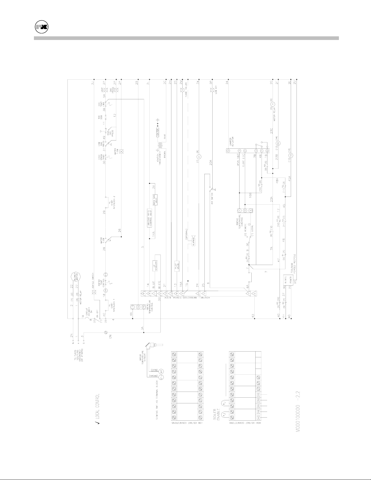
Modu-Fire® Gas-Fired Boiler Parts/Technical Support
Standard Unit - Local Control - Logic Diagram
ALARM
CUSTOMER
CONNECTIONS
FLAME SAFEY
INTERLOCK
# 2 START
INTERLOCK
# 1 START
32
Page 36
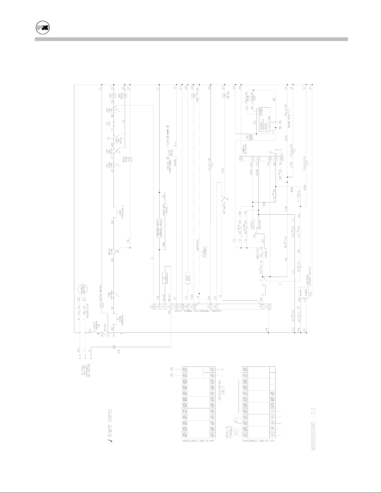
Modu-Fire® Gas-Fired Boiler Parts/Technical Support
Standard Unit - Remote Control - Logic Diagram
INPUT
ANALOG
-- +
ALARM
CUSTOMER
CONNECTIONS
FLAME SAFEY
INTERLOCK
# 2 START
INTERLOCK
# 1 START
33
Page 37
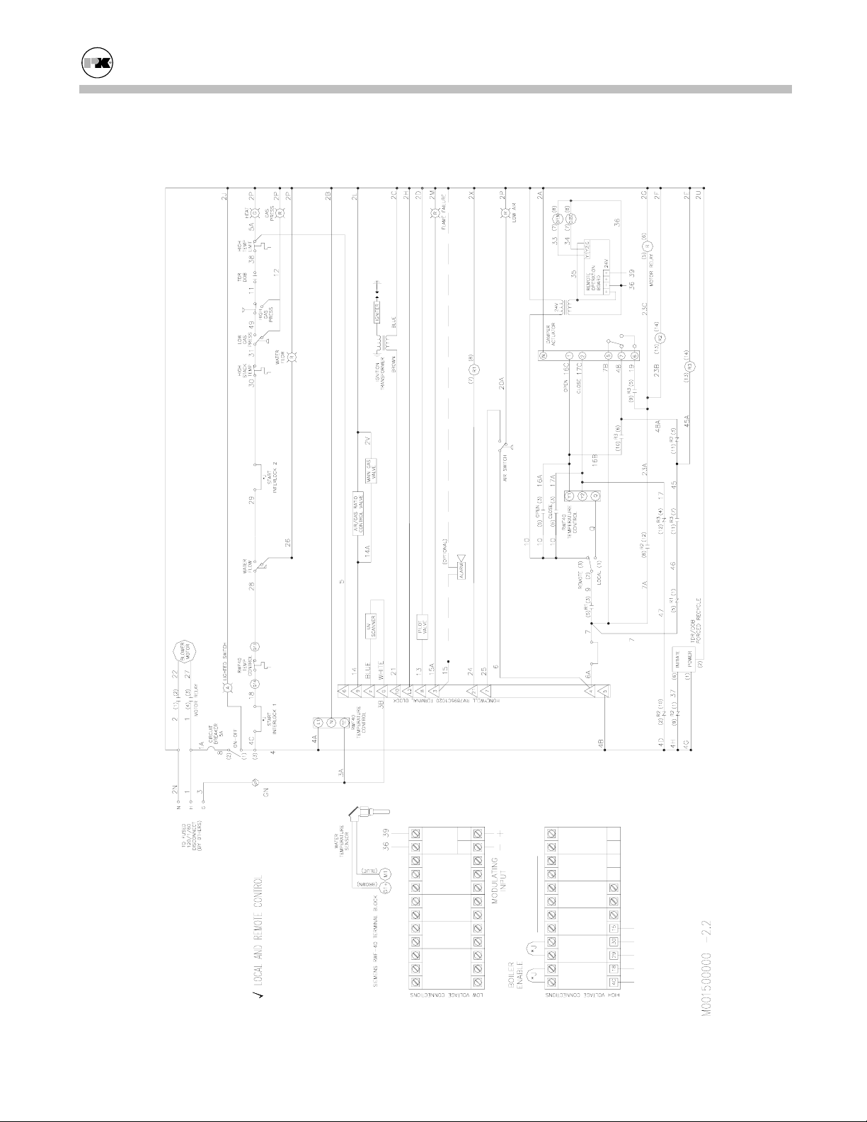
Modu-Fire® Gas-Fired Boiler Parts/Technical Support
Standard Unit - Local & Remote Control - Logic Diagram
INPUT
ANALOG
-- +
ALARM
CUSTOMER
CONNECTIONS
FLAME SAFEY
INTERLOCK
# 2 START
INTERLOCK
# 1 START
34
Page 38
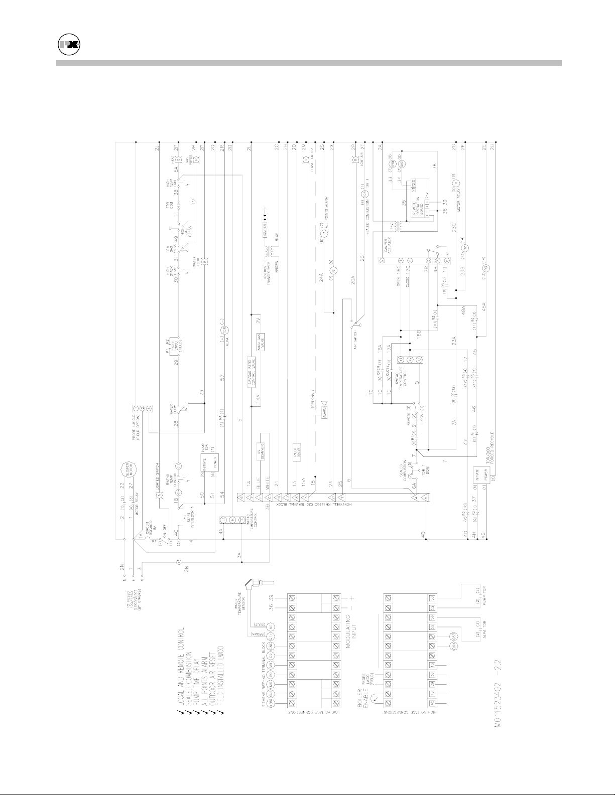
Modu-Fire® Gas-Fired Boiler Parts/Technical Support
Standard Unit - Local & Remote Control w Options - Logic Diagram
INPUT
ANALOG
-- +
SETPOINT
ALTERNATE
TEMPERATURE
OUTDOOR AIR
SETPOINT
(c)
INPUT
+V
ANALOG
+mA
CUSTOMER
CONNECTIONS
DELAY
PUMP
POINTS ALARM
ALL LIMIT
RANGE ALARM
SETPOINT
ALARM
FLAME SAFEY
INTERLOCK
# 2 START
INTERLOCK
# 1 START
35
Page 39
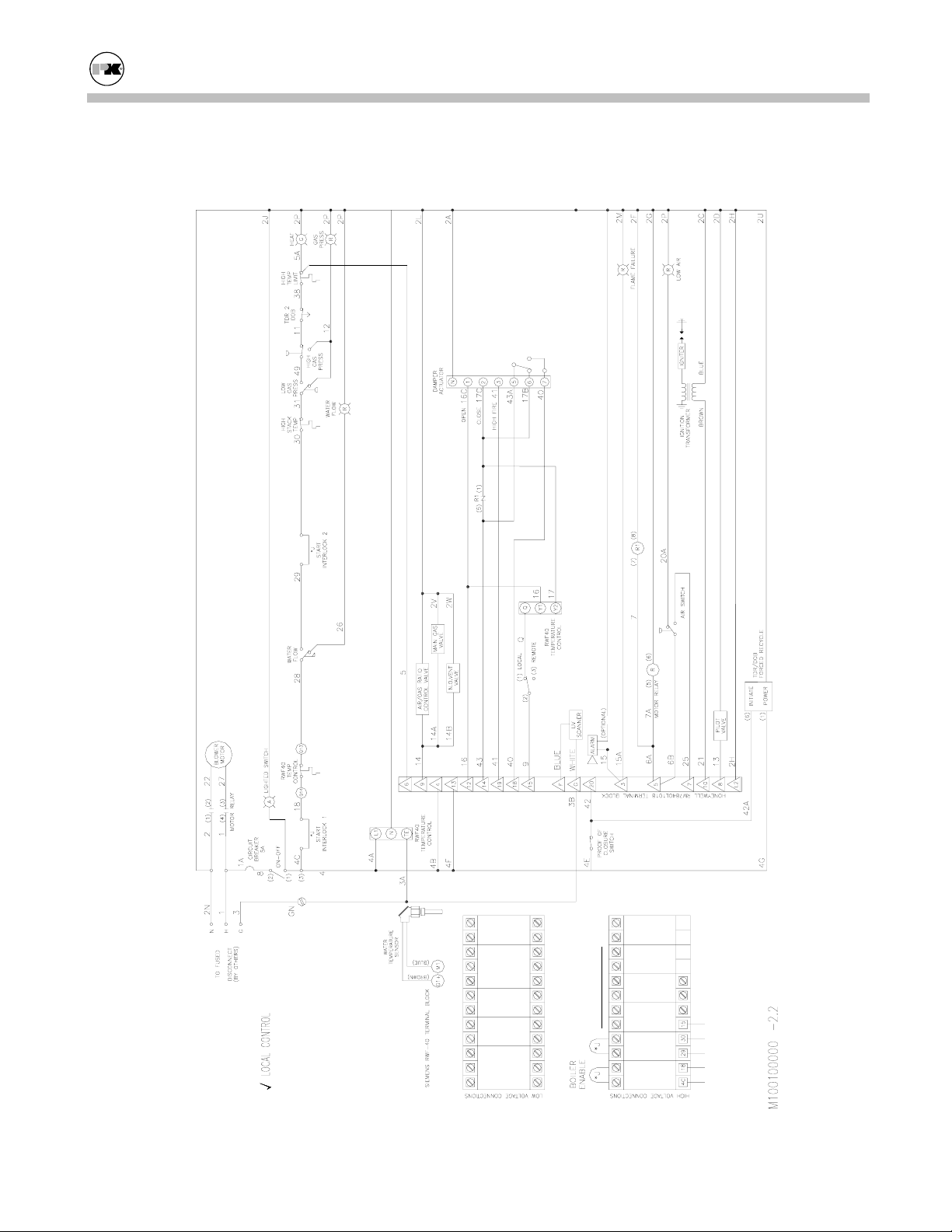
Modu-Fire® Gas-Fired Boiler Parts/Technical Support
IRI Unit - Local Control - Logic Diagram
120/1/60
ALARM
CUSTOMER
CONNECTIONS
FLAME SAFETY
INTERLOCK
# 2 START
INTERLOCK
# 1 START
36
Page 40

Modu-Fire® Gas-Fired Boiler Parts/Technical Support
IRI Unit - Remote Control - Logic Diagram
INPUT
ANALOG
-- +
120/ 1/ 60
ALARM
CUSTOMER
CONNECTIONS
FLAME SAFETY
INTERLOCK
# 2 START
INTERLOCK
# 1 START
37
Page 41
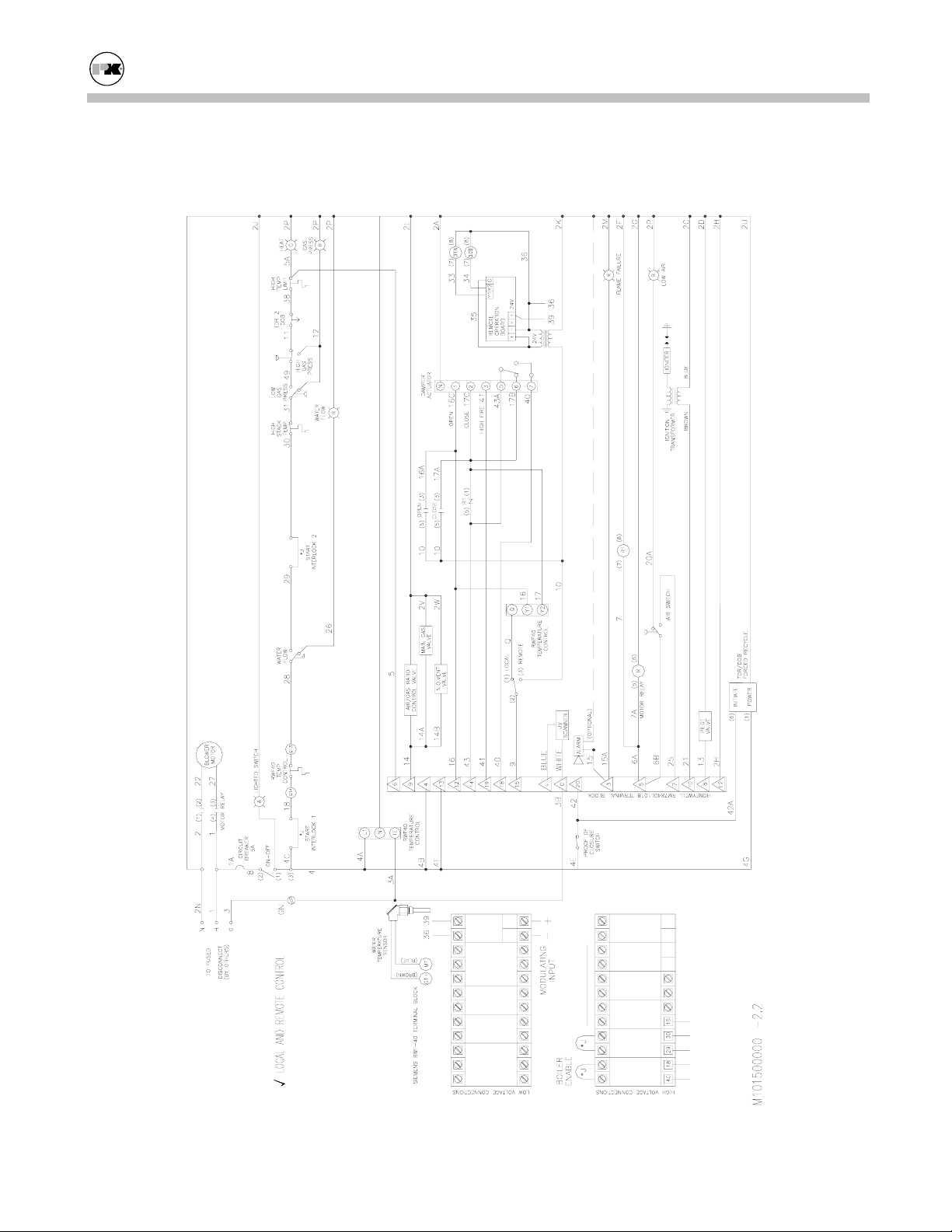
Modu-Fire® Gas-Fired Boiler Parts/Technical Support
IRI Unit - Local & Remote Control - Logic Diagram
INPUT
ANALOG
-- +
120/ 1/ 60
ALARM
CUSTOMER
CONNECTIONS
FLAME SAFETY
INTERLOCK
# 2 START
INTERLOCK
# 1 START
38
Page 42
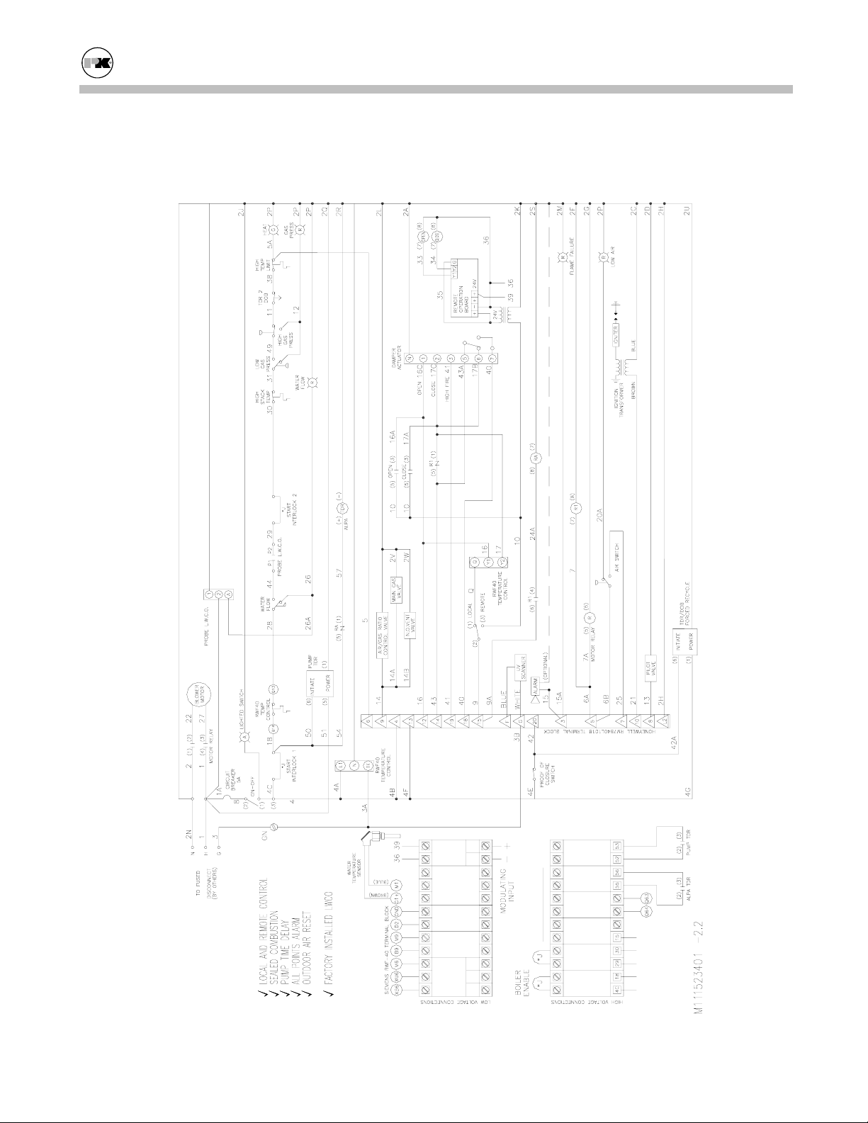
Modu-Fire® Gas-Fired Boiler Parts/Technical Support
IRI Unit - Local & Remote Control w Options - Logic Diagram
INPUT
ANALOG
-- +
120/1/60
SETPOINT
ALTERNATE
TEMPERATURE
OUTDOOR AIR
SETPOINT
(c)
INPUT
ANALOG
+mA +V
CUSTOMER
CONNECTIONS
DELAY
PUMP
POINTS ALARM
ALL LIMIT
RANGE ALARM
SETPOINT
ALARM
FLAME SAFETY
INTERLOCK
# 2 START
INTERLOCK
# 1 START
39
Page 43
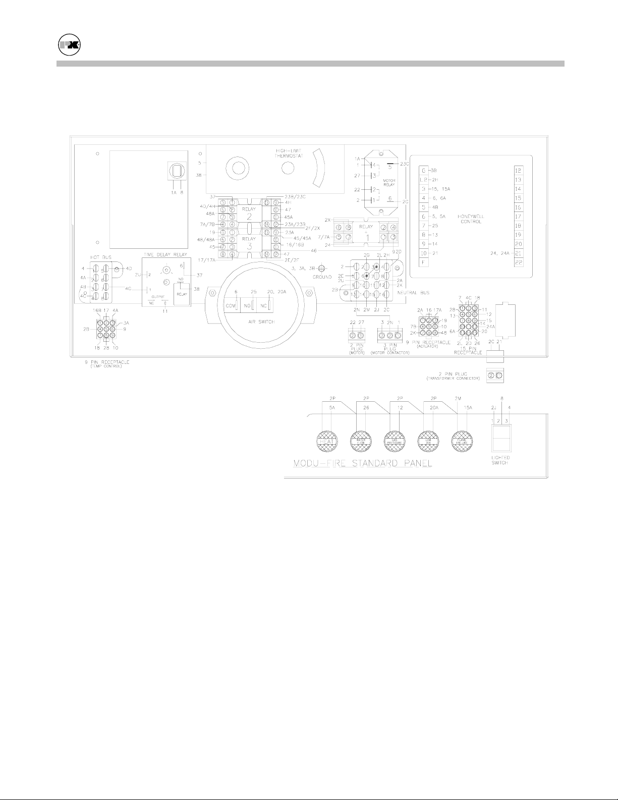
Modu-Fire® Gas-Fired Boiler Parts/Technical Support
Standard Unit – Panel Layout
40
Page 44

Modu-Fire® Gas-Fired Boiler Parts/Technical Support
IRI Unit – Panel Layout
41
Page 45
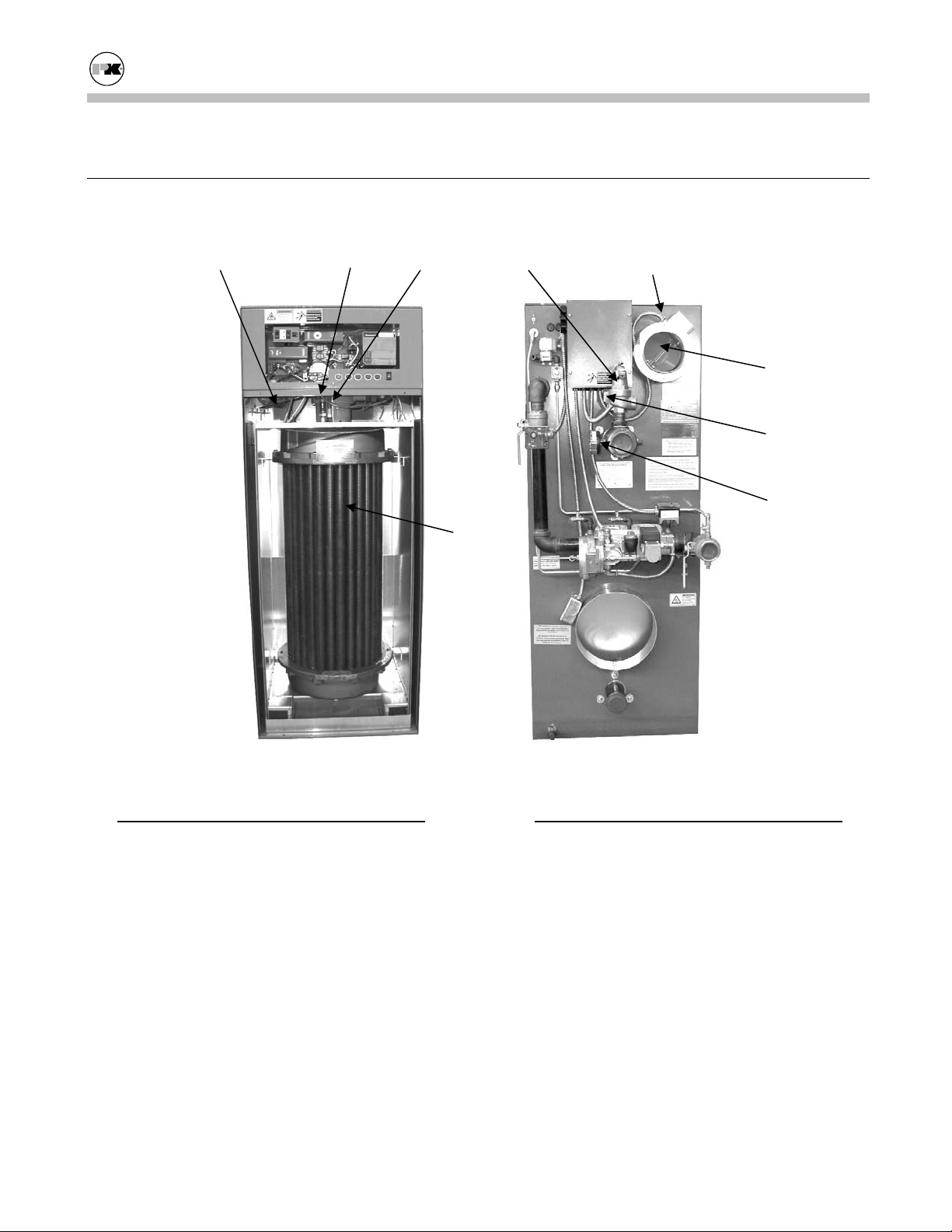
Modu-Fire® Gas-Fired Boiler Parts/Technical Support
BOILER PARTS LIST
6.2
6.2.1 Main Assembly
5 4 3
11
13, 14.
10
12
15
No. Part
1. Mixer Core, Burner (Inside Cabinet)
2. Burner Orifice (Inside Cabinet)
3. Spark Igniter Electrode
4. UV Scanner
5. Thermowell w/Clamp
6. Electrode Assembly w/Mica (Inside Cabi-
net)
7. Pilot Tube (Inside Cabinet)
8. Burner (Inside Cabinet)
9. Heat Exchanger
10. Blower Damper
11. Pressure Relief Valve (100 PSI)
9
No. Part
12. Water Flow Switch
13. Blower, Motor (Inside Cabinet)
14. Blower, Wheel (Inside Cabinet)
15. Press./Temp. Gauge
Installation/Owner’s Manual All Models-MOD
CP Control Panel (Section 6.2.2)
EC Exterior Cabinet (Section 6.2.4)
IC Interior Cabinet (Section 6.2.4)
PG Pilot Gas Train (Section 6.2.3)
MG Main Gas Train (Section 6.2.3)
42
Page 46
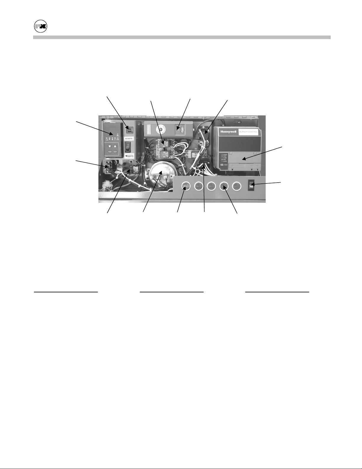
Modu-Fire® Gas-Fired Boiler Parts/Technical Support
6.2.2 Control Panel
Forced Recycle Time
No. Part
1. Thermostat (Manual Re-
set)
2. Thermostat (Oper. Temp)
3. Air Flow Switch
4. Motor Start Relay
5. Terminal Block, Neutral
6. Terminal Block, Power
Circuit Breaker
2
6
Delay Relay
Relays and
Sockets
1 4
3 12 5
Local Control Panel
No. Part
7. Flame Safeguard Programmer
7a. Amplifier (UV Scanner)
7b. Timing Card, 30 sec.
8. Programmer, Sub-Base
9. Switch, On/Off, Lighted
10. Ignition Transformer (not
visible)
7, 7a, 7b, 8
9
11
No. Part
10a. Ignition Cable (not visi-
ble)
11. Indicator Light, Red
12. Indicator Light, Green
43
Page 47
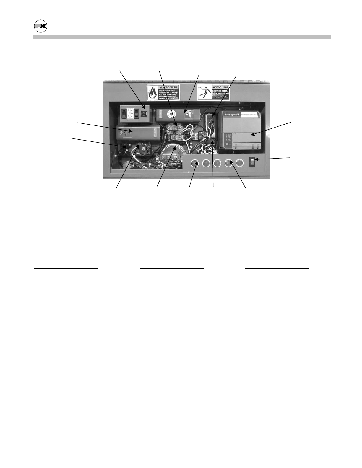
Modu-Fire® Gas-Fired Boiler Parts/Technical Support
Circuit Breaker
2
6
Forced Recycle Time
Delay Relay
No. Part
1. Thermostat (Manual Reset)
2. Thermostat (Oper. Temp)
3. Air Flow Switch
4. Motor Start Relay
5. Terminal Block, Neutral
6. Terminal Block, Power
Relays and
Sockets
3 12 5
1 4
Remote Control Panel
No. Part
7. Flame Safeguard Programmer
7a. Amplifier (UV Scanner)
7b. Timing Card, 30 sec.
8. Programmer, Sub-Base
9. Switch, On/Off, Lighted
10. Ignition Transformer (not
visible)
7, 7a, 7b, 8
9
11
No. Part
10a. Ignition Cable (not visi-
ble)
11. Indicator Light, Red
12. Indicator Light, Green
44
Page 48
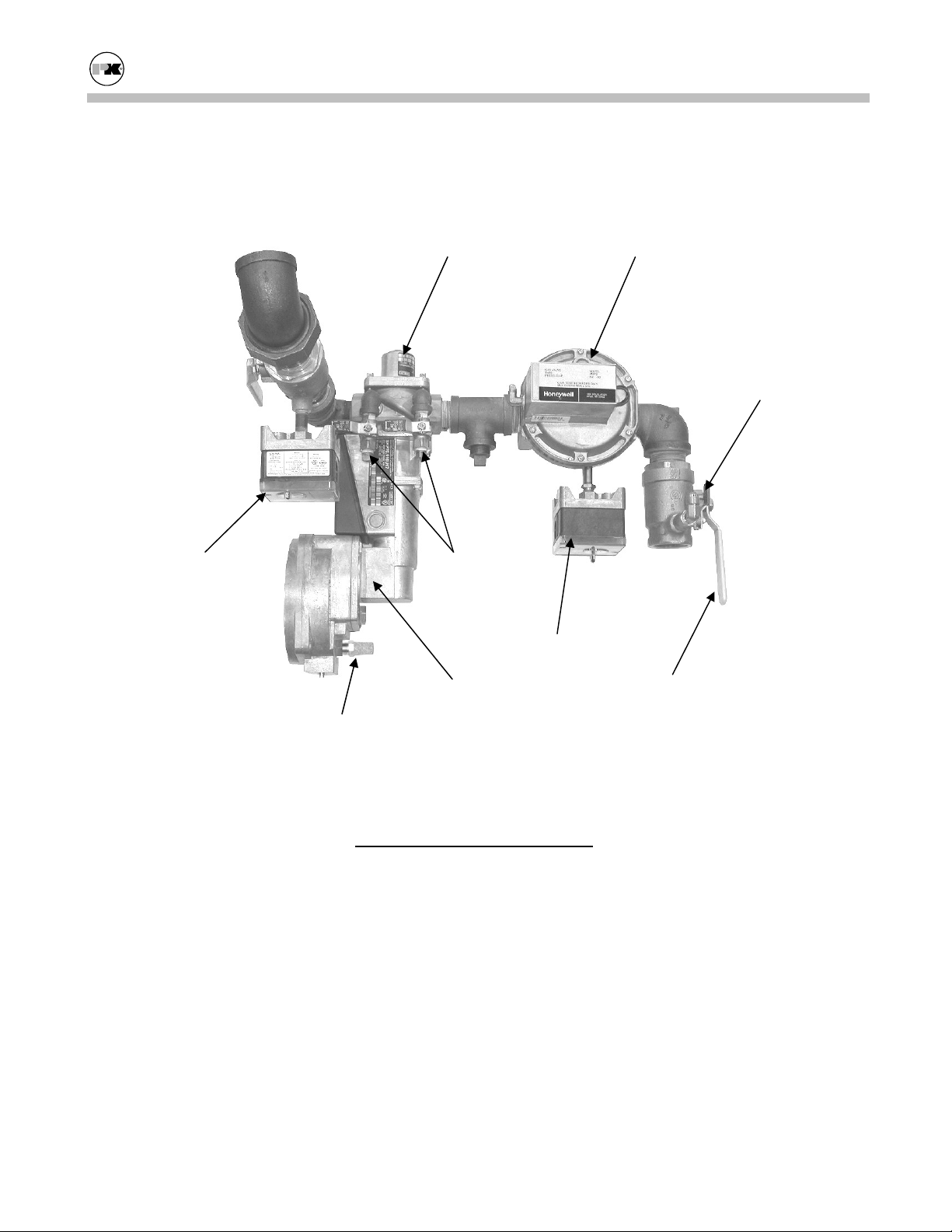
Modu-Fire® Gas-Fired Boiler Parts/Technical Support
6.2.3 Gas Trains
6.2.3.1 Standard Gas Train - 1000
3
2
8
6
7
5
9
No. Part
1. Main Gas Shutoff Cock
2. Main Gas Valve Actuator
3. Main Gas Valve
4. Air/Gas Ratio Control
5. Low Gas Pressure Switch
6. High Gas Pressure Switch
7. Leak Test Valve
8. Pilot Gas Cock
9. Vent Filter
4
1
45
Page 49

Modu-Fire® Gas-Fired Boiler Parts/Technical Support
6.2.3.2 Standard Gas Train - 1500 & 2000
6
7
5
8
9
4
No. Part
1. Main Gas Shutoff Cock
2. Main Gas Valve Actuator
3. Main Gas Valve
4. Air/Gas Ratio Control
5. Low Gas Pressure Switch
6. High Gas Pressure Switch
7. Leak Test Valve
8. Pilot Gas Cock
9. Vent Filter
3
2
1
46
Page 50

Modu-Fire® Gas-Fired Boiler Parts/Technical Support
6.2.3.3 IRI Gas Train - 1000
6
7
5
9
4
10
No. Part
1. Main Gas Shutoff Cock
2. Main Gas Valve Actuator
3. Main Gas Valve
4. Air/Gas Ratio Control
5. Low Gas Pressure Switch
6. High Gas Pressure Switch
7. Leak Test Valve
8. Normally Open Vent Valve
9. Pilot Gas Cock
10. Vent Filter
3
8
1
2
47
Page 51

Modu-Fire® Gas-Fired Boiler Parts/Technical Support
6.2.3.4 IRI Gas Train - 1500 & 2000
7
3
5
6
4
10
No. Part
1. Main Gas Shutoff Cock
2. Main Gas Valve Actuator
3. Main Gas Valve
4. Air/Gas Ratio Control
5. Low Gas Pressure Switch
6. High Gas Pressure Switch
7. Leak Test Valve
8. Normally Open Vent Valve
9. Pilot Gas Cock
10. Vent Filter
9
8
2
1
48
Page 52
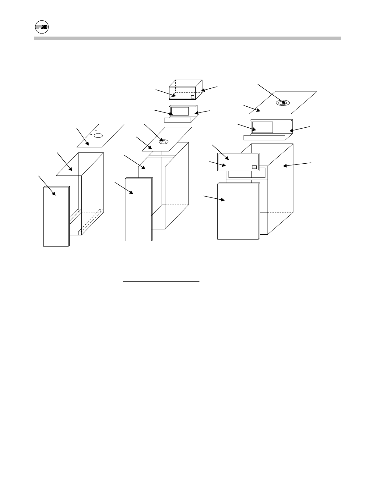
Modu-Fire® Gas-Fired Boiler Parts/Technical Support
6.2.4 Cabinet
9
10
4,5
7
11
3
12
1
6
11
8
2
IC EC EC
Internal Cabinet 1000 - External Cabinet 1500/2000 - External Cabinet
4,5
3
1
12
9
10
2
No. Part
1. Exterior Cabinet, Assy.
2. Exterior Cabinet, Door
3. Exterior Cabinet, Top
4. Sight Glass
5. Sight Glass Bezel
6. Combustion Chamber, Assy.
7. Combustion Chamber, Door
8. Combustion Chamber, Top
9. Control Panel, Label
10. Control Panel, Cover
11. Control Panel, Sub Panel
12. Control Panel, Base Assy.
49
Page 53

Modu-Fire® Gas-Fired Boiler Limited Warranty
7.0 LIMITED WARRANTY
Subject to the terms and conditions herein and except as provided below with respect to products or parts not manufactured
by Patterson - Kelley Co., Seller warrants to the original owner
at the original installation site that products manufactured by
Seller ("Products") comply, at the time of manufacture, with
recognized hydronics industry regulatory agency standards and
requirements then in effect and will be free from defects in materials and workmanship for a period of five (5) years from date
of shipment (the "Warranty Period"). For products or parts not
manufactured by Patterson - Kelley, the warranty obligations
shall, in all respects, be limited to one year.
REMEDY
The sole remedy of this warranty is expressly limited to the
repair or replacement of any part found to be defective under
conditions of normal use within the Warranty Period.
Installation is not included.
Warranty - The owner must notify the original installer of the
Product and Seller (Attention: Patterson-Kelley Co, Box 458,
East Stroudsburg, PA 18301), in writing, within the Warranty
Period, providing a detailed description of all claimed defects.
Transportation to the factory or other designated facility for
repairs of any products or items alleged defective shall, in all
events, be the responsibility and at the cost of the owner.
EXCLUSIONS
Seller shall have no liability for and this warranty does not
cover:
A. Incidental, special or consequential damages, such as loss
of the use of products, facilities or production, inconvenience, loss of time or labor expense involved in repairing
or replacing the alleged defective Product.
B. The performance of any Product under conditions varying
materially from those under which such Product is usually
tested under industry standards as of the time of
shipment.
C. Any damage to the Product due to abrasion, erosion, corro-
sion, deterioration, abnormal temperatures or the influence
of foreign matter or energy.
D. The design or operation of owner's plant or equipment or
of any facility or system of which any Product may be
made a part.
E. The suitability of any Product for any particular applica-
tion.
F. Any failure resulting from misuse, modification not au-
thorized by Seller in writing, improper installation or lack
of or improper maintenance.
G. Equipment furnished by the owner, either mounted or un-
mounted, or when contracted for by the owner to be installed or handled.
H. Leakage or other malfunction caused by:
1. Defective installations in general and specifically,
any installation which is made:
a. in violation of applicable state or local plumbing
housing or building codes,
b. contrary to the written instructions furnished
with this unit
2. Adverse local conditions in general and, specifically,
sediment or lime precipitation in the tubes and/or
headers or corrosive elements in the atmosphere.
3. Misuse in general and, specifically, operation and
maintenance contrary to the written instructions furnished with the unit, disconnection, alteration or addition of components or apparatus, not approved by
seller, operation with fuels or settings other than those
set forth on the rating plate or accidental or exterior
damage.
I. Production of noise, odors, discoloration or rusty water.
J. Damage to surrounding area or property caused by leakage
or malfunction.
K. Costs associated with the replacement and/or repair of the
unit including: any freight, shipping or delivery charges,
any removal, installation or reinstallation charges, any material and/or permits required for installation, reinstallation
or repair, charges to return the boiler and or components.
Seller's liability under this warranty shall not in any case
exceed the amount paid for the Product found to be defective.
THIRD-PARTY WARRANTIES
For goods or components not manufactured by Seller, the warranty obligations of Seller shall, in all respects, conform and be
limited to one year from the date of shipment.
SEVERABILITY
To the extent that any provision of this warranty would be void
or prohibited under applicable law, such provisions shall be
limited in effect to the minimum extent necessary to render the
remaining provisions hereof enforceable.
NO OTHER WARRANTIES
Seller makes no implied warranty of merchantability or fitness
for a particular purpose or other warranties with respect to any
products or services except as expressly set forth in this limited
warranty.
50
Page 54
MODU-FIRE® BOILER
START-UP REPORT
BOILER SERIAL # ___________________________ MODEL # _________________ DATE_________________
INSTALLATION: Name: __________________________________________________
City: _________________________ State: ______ Zip: __________
Installer Name: ____________________ Type of Installation: _________________(Hotel, School, Etc)
1. Factory Fire-Test: (copy from boiler label)
High Low
Cabinet Air "w.c. "w.c. 2. Combustion Air Temperature ° F
Inlet Gas "w.c. "w.c. 3. Water Inlet temperature: ° F
Manifold Gas "w.c. "w.c. Water Outlet temperature: ° F
Oxygen (O2) % % gpm flow through boiler
Carbon Dioxide (CO2) % % 4. a. Operating Temperature Setpoint: ° F
Carbon Monoxide (CO) ppm ppm
Net Stack Temperature ° F ° F b. Bias Setting
Pilot Gas Pressure "w.c. c. Ratio Setting
Pilot Flame Signal Volts 5. Approximate stack lengths:
Main Flame Signal Volts Ft. Horizontal
Start-Up Field Test: DATE: " w.c. (Low)
High Mid Low 7. Incoming Electrical Power Volts a.c.
Cabinet Air "w.c. "w.c. "w.c.
Inlet Gas "w.c. "w.c. "w.c. 8. Total cycles:
Manifold Gas "w.c. "w.c. "w.c. 9. Total hours
Oxygen (O2) % % % 10. Fault Cycle
Carbon Dioxide (CO2) % % % 11. Fault Hours
Carbon Monoxide (CO) ppm ppm ppm 12. Fault Code
(from internal OR external control)
Ft. Vertical
Flue Pipe Diameter
6. Draft (measured where stack exits boiler)
"w.c.
Less than 1 volt between neutral and ground
Net Stack Temperature ° F 13. What time in ignition cycle?
Pilot Gas Pressure "w.c. Additional Comments:
Pilot Flame Signal Volts
Main Flame Signal Volts Volts Volts
Cam Setting
RED ORANGE BLUE
Performed by: Please return a copy to P-K, ATTN: Boiler Tech. Support Department
Patterson-Kelley • 100 Burson Street • E. Stroudsburg, PA 18301
P) 570-476-7261 F) 570-476-7247 www.pkboilers.com
 Loading...