

Patterson-Kelley Thermific Installation & Owner's Manual
PATTERSON-KELLEY
THERMIFIC®
GAS-FIRED BOILER
Installation Date: _______________________
100 Burson Street, P.O. Box 458,
East Stroudsburg, PA 18301
Telephone: (877) 728-5351, Facsimile: (570) 476-7247
www.pkboilers.com
C.S.A Design-Certified
Complies with ANSI Z21.13/CSA 4.9
Gas-Fired Low Pressure Steam and Hot Water
Boilers
ASME Code, Section IV
Certified by Patterson-Kelley
C.S.A Design-Certified
Complies with ANSI Z21.13/CSA 4.9
Gas-Fired Low Pressure Steam and Hot Water
Boilers
TBIG-02
INSTALLATION
OWNER’S
&
MANUAL
INSTALLATION
OWNER’S
&
MANUAL
INSTALLATION
OWNER’S
&
MANUAL
INSTALLATION
OWNER’S
&
MANUAL
INSTALLATION
OWNER’S
&
MANUAL
INSTALLATION
OWNER’S
&
MANUAL
INSTALLATION
OWNER’S
&
MANUAL
INSTALLATION
OWNER’S
&
MANUAL


Thermific® Gas-Fired Boiler Table of Contents
1.0 INTRODUCTION ................................. 1
2.0 SAFETY............................................... 1
2.1 General ......................................................1
2.2 Training......................................................1
2.3 Safety Features..........................................1
2.4 Safety Labels .............................................2
2.5 Safety Precautions.....................................2
2.5.1 Electrical Hazards .............................2
2.5.2 Burn, Fire, and Explosion Hazards ...2
2.5.3 Crush Hazards ..................................3
2.5.4 Chemical Hazards.............................3
2.5.5 Pressure Hazards .............................4
2.5.6 Slip, Fall Hazards..............................4
3.0 INSTALLATION ................................... 5
3.1 Receiving and Storage ..............................5
3.1.1 Initial Inspection ................................5
3.1.2 Storage Prior to Installation...............5
3.2 Compliance with Codes .............................5
3.3 Setup .........................................................5
3.3.1 Foundation ........................................5
3.3.2 Placement .........................................5
3.3.3 Clearances........................................6
3.4 Electrical Connections ...............................6
3.5 Combustion Air ..........................................7
3.6 Flue Venting...............................................7
3.6.1 Vent Elbows ......................................8
3.6.2 Barometric Damper...........................8
3.6.3 Barometric Damper Location ............8
3.6.4 Flue Connection................................8
3.6.5 Vent Termination...............................9
3.6.6 Removing an Existing Boiler .............9
3.7 Gas Piping .................................................9
3.7.1 Gas Supply Piping by Installer ........11
3.7.2 Gas Bleeds and Vents ....................11
3.8 Boiler Water Piping..................................11
3.8.1 Piping Design..................................11
3.8.2 Boiler Inlet and Outlet Connections 12
3.8.3 Boiler Water Piping by Installer.......12
3.8.4 Flushing and Filling.........................13
3.9 Burner and Ignition System .....................13
3.9.1 Inspection .......................................13
3.10 Pre-Start Check List...............................13
3.11 Safety Checks........................................13
3.11.1 Test of Ignition Safety System ...... 13
3.11.2 Test of Low Water Cut-off.............14
3.11.3 Test of High-Limit Control ............. 14
3.11.4 Test of Gas Pressure Switch ........14
3.12 Initial Adjustments..................................15
3.12.1 Operating Temperature Controller for
Lo-Hi-Lo Thermific
®
.............................15
3.12.2 Gas Pressure Adjustment.............16
3.12.3 Air Flow Adjustments .................... 16
4.0 OPERATION ..................................... 19
4.1 General....................................................19
4.1.1 Control Panel Front.........................19
4.1.2 Tests ............................................... 19
4.2 Lighting and Shut-Down Procedures.......19
4.2.1 Lighting Procedures........................19
4.2.2 Normal Shut Down Procedures ......20
4.2.3 Emergency Shut Off .......................20
4.3 Typical Boiler Operating Conditions ........20
5.0 MAINTENANCE ................................ 21
5.1 Maintenance and Inspection Schedule.... 21
5.1.1 Daily................................................21
5.1.2 Weekly ............................................ 21
5.1.3 Monthly (During Operation) ............21
5.1.4 Semi-Annually.................................21
5.1.5 Annually .......................................... 22
Thermific® Gas-Fired Boiler Table of Contents
5.2 Cleaning the Burner.................................22
5.2.1 Semi-Annual Cleaning ....................22
5.2.2 Annual Cleaning .............................22
5.3 Removing the Exchanger ........................23
5.4 After All Repairs or Maintenance .............23
5.5 Sequence Of Operation ...........................23
5.6 Troubleshooting .......................................24
6.0 PARTS/TECHNICAL SUPPORT .......26
6.1 Wiring Diagrams ......................................27
6.1.1 On-Off .............................................28
6.1.1a On-Off IRI .....................................30
6.1.2 Lo-Hi-Lo .......................................... 32
!
WARNING
Improper use may
result in fire or injury.
Read instructions/safety
manual before installing,
c
1998 HCS, Inc. 800-748-0241
WARNING!
It is essential to read, understand, and follow the recommendations of this manual before installing, operating, or servicing this equipment. Failure to do so could
result in fire or explosion and serious injury, death,
and/or property damage.
The same features which permit this boiler to achieve
high-efficiency performance make it unlike most other
boilers of this general size, so it is important to understand how this boiler operates.
Do not store or use gasoline or other flammable vapors
or liquids in the vicinity of this or any other appliance.
WARNING!
operating or servicing boiler.
Reorder No. 6020-V2WHPK
6.1.2a Lo-Hi-Lo IRI ..................................34
6.1.3 Water Cut-Off.................................. 36
6.2 Boiler Parts List .......................................38
6.2.1 Main Assembly ...............................38
6.2.2 Control Panel.................................. 39
6.2.3 Gas Train........................................ 40
6.2.4 Cabinet ...........................................41
7.0 LIMITED WARRANTY ....................... 42
7.1 Express Warranty .................................... 42
7.2 Warranty Disclaimer ................................ 42
What to do if you smell gas:
• Do not try to light any appliance.
• Do not touch any electrical switch.
• Do not use any phone in your building. Immedi-
ately call your gas supplier from a neighbor's
phone. Follow the gas supplier's instructions.
• If you cannot reach your gas supplier call the fire
department.
Installation and service must be performed by a qualified installer, service agency, or gas supplier.
Thermific® Gas-Fired Boiler Introduction/Safety
1.0 INTRODUCTION
The P-K Thermific® Gas-Fired Boiler combines a radial pre-mix fan-assisted burner with a compact, finned-tube heat exchanger to provide maximum efficiency in a minimum of space. The high-quality materials and thoroughly tested design of the boiler should
provide years of trouble-free, hot-water service, if the
instructions in this manual are followed carefully.
This manual covers installation of P-K Thermific
®
Boiler Series 700, 1000, 1200, 1500, 1700, and 2000.
The model numbers may be followed by a prefix or
suffix letter in some cases to indicate special features
or different options.
While details may differ slightly, basic operation is the
same for all models. Boilers may be built to operate
with natural gas or liquefied petroleum gas (propane).
Check the rating plate for correct fuel usage and gas
pressures.
The boiler is only a part of the complete heating system. This boiler may be fully operational and yet because of poor circulation, control or other operating
characteristics, not deliver heat to the desired location.
Additional equipment such as temperature sensors,
pumps, flow switches, balancing valves and check
valves will be required for satisfactory operation of
any system. Patterson-Kelley cannot be responsible
for the design or operation of such systems and a
qualified engineer or contractor must be consulted.
2.0 SAFETY
2.1
GENERAL
The Thermific gas-fired boiler must be:
• Installed by qualified personnel in accordance with
designs prepared by qualified facility engineers including: structural, mechanical, electrical, and
other applicable disciplines.
• Operated and serviced by qualified, properly
trained personnel in accordance with all applicable
codes, laws, and regulations.
2.2
TRAINING
!
WARNING
Improper use may
result in fire or injury.
Read instructions/safety
manual before installing,
c
1998 HCS, Inc. 800-748-0241
operating or servicing boiler.
Reorder No. 6020-V2WHPK
It is essential to read, understand, and follow the recommendations of this manual before installing, operating, or servicing this equipment. Failure to do so
could result in serious injury, death, and/or property
damage.
Proper training is the best protection against accidents.
Operating and service personnel must be thoroughly
familiar with the basic construction of the Thermific
boiler, the use and locations of the controls, the operation of the boiler, adjustment of its various mechanisms, and all applicable safety precautions. If any of
the provisions of this manual are not fully and completely understood, contact the Patterson-Kelley Sales
Department toll-free at (877) 728-5351 for assistance.
2.3
SAFETY FEATURES
It is the responsibility of the customer to maintain the
safety features of this machine, such as: guards, safety
labels, safety controls, interlocks, lockout devices, etc.,
in place and operable.
• Operated and serviced in accordance with a com-
prehensive safety program determined and established by the customer. Do not attempt to operate
or service until such a program has been established.
Page 1
Thermific® Gas-Fired Boiler Safety
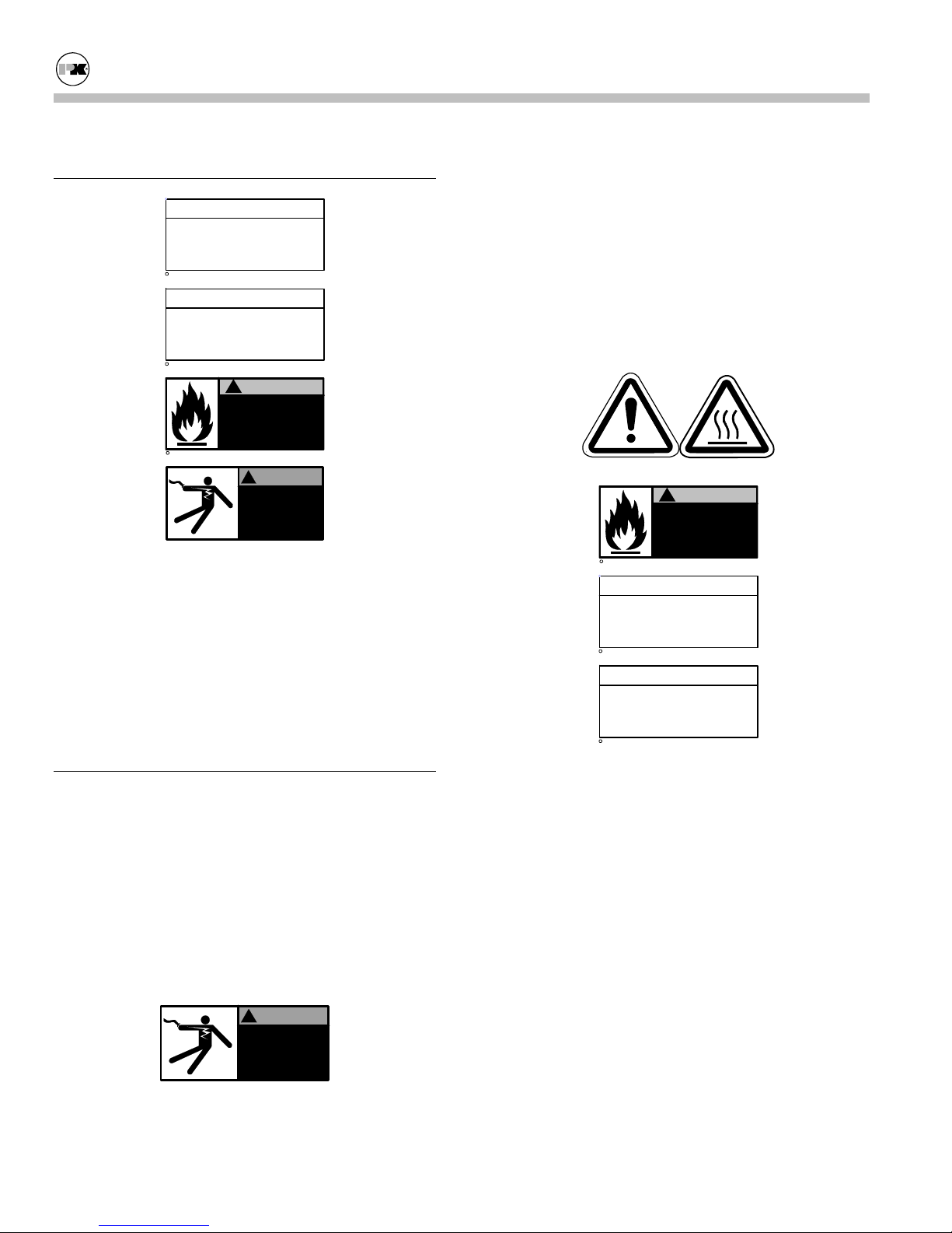
2.4 SAFETY LABELS
NOTE
Make sure this union is
tight before closing cabinet
cover after servicing boiler.
c
1998 HCS, Inc. 800-748-0241
Reorder No. 8032-02NHAK
NOTE
When opening leak test valves,
always follow instructions in
operation and safety manual.
c
1998 HCS, Inc. 800-748-0241
Improper use may
result in fire or injury.
Read instructions/safety
manual before installing,
c
1998 HCS, Inc. 800-748-0241
C 1998 HCS, Inc. 800-748-0241
operating or servicing boiler.
The safety labels shown above are affixed to your
boiler. Although the labels are of high quality, they
may become dislodged or unreadable over time. Contact Patterson-Kelley toll-free at (877) 728-5351 for
replacement labels.
2.5
SAFETY PRECAUTIONS
Reorder No. 8032-01NHPK
!
WARNING
Reorder No. 6020-V2WHPK
!
WARNING
Electrical hazard.
Follow lockout/tagout
procedure when
servicing this boiler.
Reorder No. 5025-V1WHPK
• Shock hazard! Properly lockout/tagout the electri-
cal service and all other energy sources before
working on or near the machine.
• Shock hazard! Boiler is not rated for wash-down
service.
2.5.2 Burn, Fire, and Explosion Hazards
General Warning
c
1998 HCS, Inc. 800-748-0241
Improper use may
result in fire or injury.
Read instructions/safety
manual before installing,
operating or servicing boiler.
Hot Surface
!
WARNING
Reorder No. 6020-V2WHPK
NOTE
Make sure this union is
tight before closing cabinet
cover after servicing boiler.
c
1998 HCS, Inc. 800-748-0241
Reorder No. 8032-02NHAK
NOTE
When opening leak test valves,
always follow instructions in
operation and safety manual.
c
1998 HCS, Inc. 800-748-0241
Reorder No. 8032-01NHPK
Provide a suitable location for the boiler, away from
normal personnel traffic, with adequate working space,
adequate clearances, proper ventilation and lighting,
with a structure sufficiently strong and rigid to support
the weight of the boiler, all piping, and accessories.
2.5.1 Electrical Hazards
!
WARNING
Electrical hazard.
Follow lockout/tagout
procedure when
servicing this boiler.
C 1998 HCS, Inc. 800-748-0241
Reorder No. 5025-V1WHPK
Page 2
• Burn, fire, and explosion hazards! Installation
must be in strict conformance to all applicable
codes and standards including NFPA 54, ANSI
Z223.1 and CAN/CGA B.149. Install all required
ventlines for gas devices. Refer to Section 3.7.2
below.
• Hazard from incorrect fuels! Possible fire, explo-
sion, overheating, and damage. Do not use any
fuels except the design fuel for the unit.
• Overfire hazards! High pressure in gas or propane
supply could result in overfiring of other devices
supplied from the same source.
• Fire and explosion hazards! Close the main gas
shutoff before servicing boiler.
Thermific® Gas-Fired Boiler Safety
• Fire and explosion hazards! Do not store or use
gasoline or other flammable vapors or liquids in
the vicinity of this or any other gas fired appliance.
• Burn hazard! Possible hot surfaces. Do not touch
gas vent during firing operation. Use only factory
recommended vent components.
• Burn hazard! Hot fluids. Use caution when ser-
vicing or draining boiler.
• Fire and explosion hazards! Use caution when
servicing burner. Propane (LPG) is heavier than
air and may linger in the combustion chamber,
vent lines, or elsewhere.
• Gas leak hazard! Make sure all connections to
main burner are tight when reassembling the
burner. These connections cannot be tested after
the burner is assembled.
• Gas leak hazard! All threaded gas connections
must be made using a pipe compound that is resistant to liquefied petroleum. Do not use Teflon
tape on threaded gas piping.
• Gas leak hazard! Check entire gas train for leaks
after installation. If there is a smell of gas, shut
down the boiler and obtain immediate assistance
from trained service personnel and/or your local
fire department.
• Overfire hazard! Possible fire and explosion from
excess gas pressure. Make sure that gas inlet pressure does not exceed 14 inches W.C. to the regulator.
• Overfire hazard! Possible fire and explosion.
Possible malfunction of regulators and/or motorized gas valves. Maintain all gas train components
in good condition. Do not alter wiring connections. Annual inspection by factory-trained personnel for proper set-up and operation is recommended.
• Overfire and underfire hazards! Possible fire, ex-
plosion, overheating, and component failure. Do
not attempt to adjust firing rate of the boiler. The
firing rate must be adjusted only by factory trained
personnel.
2.5.3 Crush Hazards
General Warning
• Lifting hazards! Use properly rated lifting equip-
ment to lift and position the boiler. The load is
unbalanced. Test balance before lifting 3 ft. above
the floor. Do not allow personnel beneath the
lifted load. Refer to approximate weights in the
table below:
Boiler Size Weight in Pounds
700,000 Btu 595
1,000,000 Btu 595
1,200,000 Btu 685
1,500,000 Btu 990
1,700,000 Btu 985
2,000,000 Btu 1,025
• Bump hazard from overhead piping. Install piping
with adequate vertical clearance.
2.5.4 Chemical Hazards
• Environmental hazard! The motorized gas valves
may contain hydraulic oil. Use safe procedures
for the disposal of all lubricants.
• Chemical hazards from cleaning products. Use
caution when cleaning the system. The use of professional assistance is recommended. Use safe
procedures for the disposal of all cleaning solutions.
Page 3
Thermific® Gas-Fired Boiler Safety
2.5.5 Pressure Hazards
!
WARNING
Improper use may
result in fire or injury.
Read instructions/safety
manual before installing,
c
1998 HCS, Inc. 800-748-0241
operating or servicing boiler.
• Pressure hazard! Hot fluids. Install isolation
valves on boiler water inlet and outlet. Make sure
isolation valves are closed before servicing boiler.
• Pressure hazard! Hot fluids. Annually test safety
relief valve for proper operation. Do not operate
boiler with faulty relief valve.
2.5.6 Slip, Fall Hazards
!
WARNING
Improper use may
result in fire or injury.
Read instructions/safety
manual before installing,
c
1998 HCS, Inc. 800-748-0241
operating or servicing boiler.
• Tripping hazard! Do not install piping on floor
surfaces. Maintain clear path around boiler.
• Slip and fall hazard! Use drip pan to catch water
while draining the boiler. Maintain dry floor surfaces.
• Slip and fall hazard! Do not locate intake or ex-
haust terminations directly above a walkway;
dripping of condensation can cause icing of the
walking surface.
Page 4

Thermific® Gas-Fired Boiler Installation
3.0 INSTALLATION
RECEIVING AND STORAGE
3.1
3.1.1 Initial Inspection
Upon receiving the boiler, inspect it for signs of shipping damage. Pay particular attention to the control
panel on the top of the boiler and the components
mounted on the back, which may show damage from
mishandling.
The exterior cabinet must be reasonably air-tight for
the burner to operate correctly. Leaks caused by dents
in the sheet metal or panels out of position may cause
the limit controls to show Low Air. Check to be sure
that the mixer core in the top burner is centered and
has not moved in shipment; (see Section 5.2, "Cleaning the Burner" for proper location). Verify that the
total number of pieces shown on the packing slip
agrees with those actually received.
Important: Note any damage or shortage on the
freight bill and immediately notify the carrier. File
all claims for shortage or damage with the carrier.
3.1.2 Storage Prior to Installation
If the boiler is not installed immediately, it must be
stored in a location adequately protected from the
weather, preferably indoors. If this is not possible,
then it should remain in the shipping container and be
covered by a tarpaulin or other waterproof covering.
Note: Controls and other equipment that are damaged
or fail due to weather exposure are not covered by
warranty.
3.2
COMPLIANCE WITH CODES
The P-K Thermific® Boiler with standard components
and many options complies with American National
Standard/CSA Standard ANSI Z21.13/CSA 4.9, latest
edition, Gas-Fired Low Pressure Steam and Hot Water
Boilers. The heat exchanger is constructed and
stamped in accordance with ASME Boiler and Pres-
sure Vessel Code, Section IV for 160 psig maximum
operating pressure and/or 250º F maximum operating
temperature. Other codes or approvals which apply
will be labeled on the boiler.
Installation of the boiler must conform to all the requirements of all national, state and local codes established by the authorities having jurisdiction or, in the
absence of such requirements, in the U.S. to the National Fuel Gas Code, ANSI Z223.1/NFPA 54, latest
edition. In Canada, the equipment shall be installed in
accordance with the current Installation Code for Gas
Burning Appliances and Equipment, CAN/CGAB.149, and applicable Provincial Regulations for the
class, which should be carefully followed in all cases.
Authorities having jurisdiction should be consulted
before installations are made.
Where required by local codes, the installation must
conform to American Society of Mechanical Engineers Safety Code for Controls and Safety Devices for
Automatically Fired Boilers (ASME CSD-1).
3.3
SETUP
3.3.1 Foundation
Provide a firm, level foundation, preferably of concrete.
Note: The boiler may be installed on a combustible
floor; however, the boiler must never be installed on
carpeting.
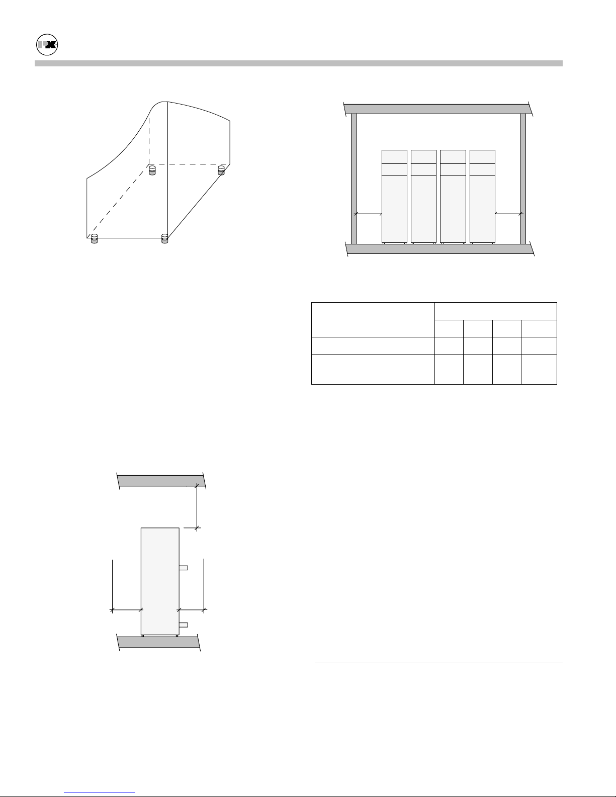
3.3.2 Placement
The boiler must be level to function properly. To assist in leveling the boiler, the four (4) leg bolts (1/2"NC) holding the boiler to the shipping skid must be
reinstalled in the threaded legs on the bottom. The
adjustable legs are also necessary to provide adequate
floor clearance and prevent distortion on the cabinet,
(twisting, etc.) in addition to leveling.
Page 5
Thermific® Gas-Fired Boiler Installation
DD
Adjustable Legs for Leveling and Floor Clearance
3.3.3 Clearances
If the boiler is to be installed near combustible surfaces, the minimum clearances shown in the table below must be maintained.
Failure to provide for the service access clearances,
even with non-combustible surfaces, may cause future
problems servicing the boiler.
The boiler must be installed in a space large in comparison to the boiler as described in Section 6.3 of the
National Fuel Gas Code, ANSI Z223.1, latest edition.
Minimum Clearances from Adjacent Walls, Ceiling, and
Type of Surface
Dimensions (inches)
Obstructions
A B C† D
Combustible Surfaces 30 24 24 24
Non-combustible Sur-
30 24* 24 24**
faces
† "C" dimension includes clearance to remove the
burner. Do not put pipes, ducts, etc. in this area above
the boiler.
* CSA minimum. Actual clearance depends upon
stacking requirements.
No pipes,
ducts, etc.
in this area.
AB
C
Page 6
** Service access need be only on one side of a boiler
or row of boilers. Boilers may be installed immediately adjacent to each other. However, P-K recommends this clearance between each boiler when there
is insufficient access at the rear to allow for service
and adjustment.
In Canada: The boilers are approved for installation
with zero clearance to combustible surfaces, but 24
inch service clearances are recommended.
ELECTRICAL CONNECTIONS
3.4
The boiler is wired for 120 volts, single phase, 60
hertz. The total operating amperage is indicated on the
rating nameplate. The 700 and 1000 series require less
than 8 amps; the 1200 series less than 9 amps; the
1500, 1700, 2000 series less than 12 amps. Before
Thermific® Gas-Fired Boiler Installation
starting the boiler, check to ensure that the proper
voltage and amperage is connected to the boiler.
An external electrical disconnect (not supplied with
the boiler) with adequate overload protection is required. The boiler must be grounded in accordance
with local codes or in the absence of such requirements, in the U.S. with National Electrical Codes,
ANSI/NFPA No. 70 latest edition and in Canada, wire
according to the current Canadian Electrical Code.
Note: A dedicated earth ground (green wire) is required to avoid nuisance shutdowns. Do not ground
through the conduit. It is also important that proper
polarity be maintained.
COMBUSTION AIR
3.5
Combustion air must be free from dust, lint, etc. The
presence of such materials in the air supplied to the
burner could cause nuisance "Low Air" shutdowns or
premature burner failure. The boiler should not be
operated during construction while the possibility of
drywall dust, demolition dust, etc. exists.
Provisions for combustion and ventilation air must be
in accordance with Section 5.3, Air for Combustion
and Ventilation, of the National Fuel Gas Code, ANSI
Z223.1, latest edition, or applicable provisions of the
local building codes. In Canada, combustion air openings shall comply with CSA 4.9. The formula is "1 sq.
in. per 1,000 Btu/hr of gas input not less than 100 sq.
in." The location shall be "neither more than 18," nor
less than 6" above the floor level.
The boiler room shall be provided with two openings
to ensure adequate combustion air and proper ventilation. One opening should be 6 to 12 inches above the
floor and the other 6 to 12 inches below the ceiling,
preferably on opposite walls. The size of each opening is determined by whether air is taken from inside
or outside the building. In Canada, ventilation air
openings shall be at least 10% of the cross sectional
area required for combustion air, but not less than 10
square inches. It is to be located at the highest practical point communicating with outdoors.
If air is taken directly from outside the building, each
opening should have a net free area of 1 square inch
for each 4,000 Btu per hour of total boiler input. For
instance, 300 square inches (2-1/12 square feet) are
required for 1,200,000 Btu per hour input.
When air is taken from the outdoors through a vertical
duct, 1 square inch per 4,000 Btu per hour is required.
If a horizontal duct is used, 1 square inch per 2,000
Btu per hour is required, i.e., 600 square inches for
1,200,000 Btu per hour input.
If air is taken from another interior space, each opening should have a net free area of 1 square inch for
each 1,000 Btu per hour of boiler input (1,200 square
inches for a 1,200,000 Btu per hour.)
WARNING!
Under no circumstances shall the boiler room ever be
under a negative pressure. Particular care should be
taken when exhaust fans, compressors, air-handling
units or other equipment may rob air from the boiler.
The combustion air supply must be completely free of
chemical fumes which may be corrosive when burned
in the boiler. Common chemicals which must be
avoided are fluorocarbons and other halogenated compounds, most commonly present as refrigerants or solvents, such as freon, trichlorethylene, perchlorethylene, chlorine, etc. These chemicals, when burned,
form acids which quickly attack the boiler tubes, tube
sheets, flue collectors and the boiler stack. The result
is improper combustion and premature boiler failure.
3.6
FLUE VENTING
For boilers connected to gas vents or chimneys, vent
installations shall be in accordance with Part 7, Venting of Equipment, of the National Fuel Gas Code,
ANSI Z223.1, or applicable provisions of the local
building codes.
This boiler is certified as Category I as it is defined in
ANSI Z21.13/CSA 4.9, latest edition. This boiler is
suitable for use with Type "B" vent.
In Canada, the boiler is certified for installation with a
"Power Venter" by the Canadian Gas Association
when installed with the "listed accessories." Consult
your local distributor for information on proper selection.
Page 7
Thermific® Gas-Fired Boiler Installation
The venting system and the horizontal portions of the
venting system shall be supported to prevent sagging.
Consult your local vent supplier for correct vent sizing
and structural support requirements. Vent diameter is
dictated by the length and height of horizontal and vertical portions of the vent installation and the materials
of construction. Correct sizing should provide a
slightly negative pressure (less than 0.1 inches of water column) at the boiler flue outlet with a stack temperature of 280º F.
3.6.1 Vent Elbows
The turn from horizontal to vertical should be made
with two 45º ells or with one long radius 90º ell for
best operation. Do not use "short radius" ells.
3.6.2 Barometric Damper
This boiler is certified for operation without a barometric damper. However, some venting installations
may require a barometric damper for smooth operation. A barometric damper is supplied with each
boiler, and when used, should be installed according to
the following guidelines.
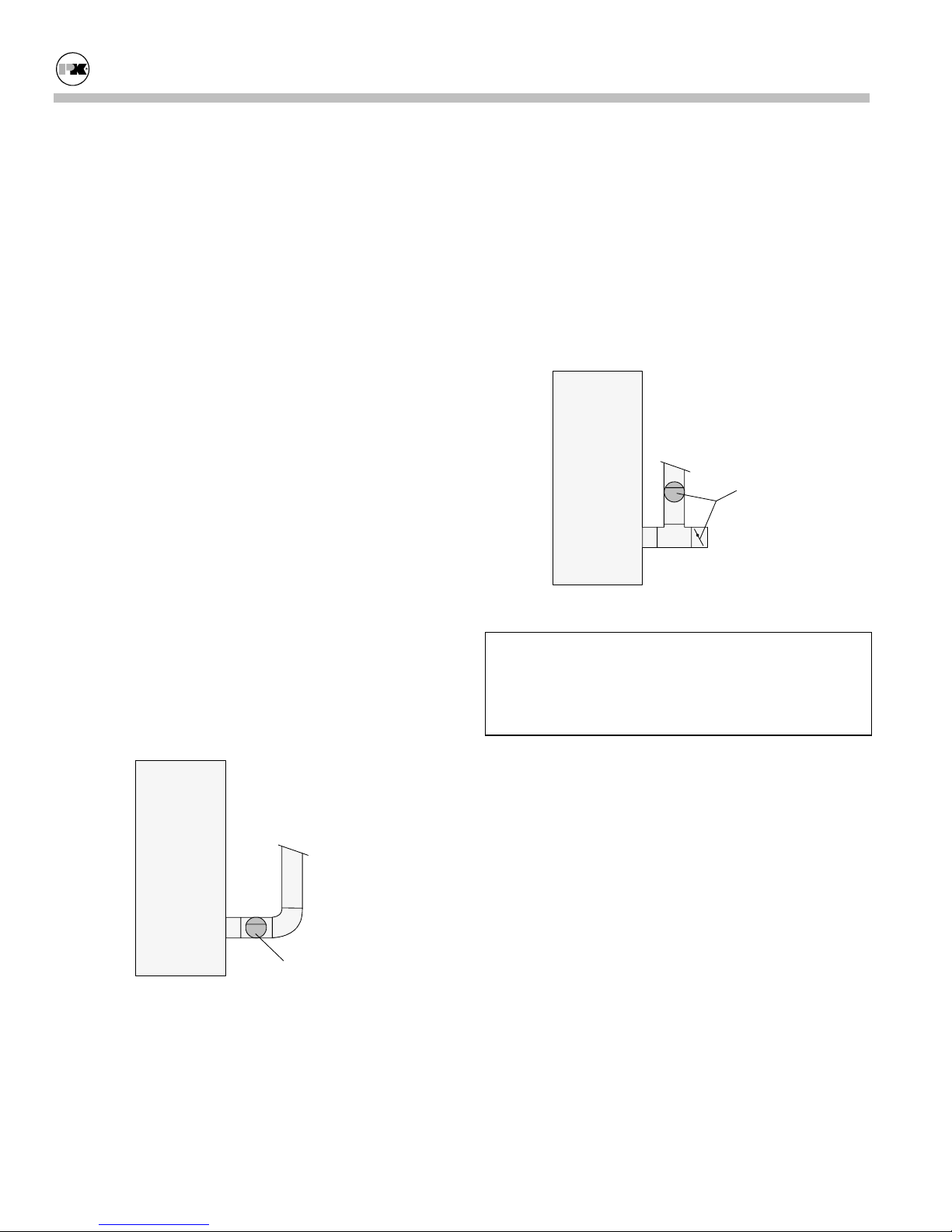
3.6.3 Barometric Damper Location
2. The damper may be located in either side of the
horizontal section of stack.
3. In a multiple boiler installation, one barometric
damper must be installed with each boiler.
Be sure that the damper is mounted horizontally (never
vertically). Be sure to remove all three red stops from
the damper before start-up. The damper door should
swing freely. Carefully follow all the instructions provided with the barometric damper.
Boiler
Barometric
Damper,
incorrect
(
locations)
Incorrect Damper Locations
WARNING!
To avoid spillage into the boiler room of dangerous
flue gas containing carbon monoxide, the opening in
the damper (draft control gate) must never face
against the flow of flue gas.
Boiler
Barometric
Damper
Correct Damper Location
1. We recommend that the barometric damper be
located immediately after the flue connector for
best operation. Consult vent supplier for specific
installation requirements.
Page 8
3.6.4 Flue Connection
The connection from the boiler to the vent should be
as direct as possible and the upward slope of any horizontal breaching should be at least 1/4 inch per linear
foot. This boiler should not be connected into any portion of a mechanical draft system operating under
positive pressure. Provisions must be made for supports to prevent contact of the vent with combustible
surfaces.
Note: If the vent is erected directly behind the boiler,
make sure that the weight of the vent is not supported
by the boiler vent collar. The collar is not designed to
support the weight of the vent. Structural support and
spacing from combustible surfaces must be in accordance with the vent manufacturer's requirements.
Thermific® Gas-Fired Boiler Installation
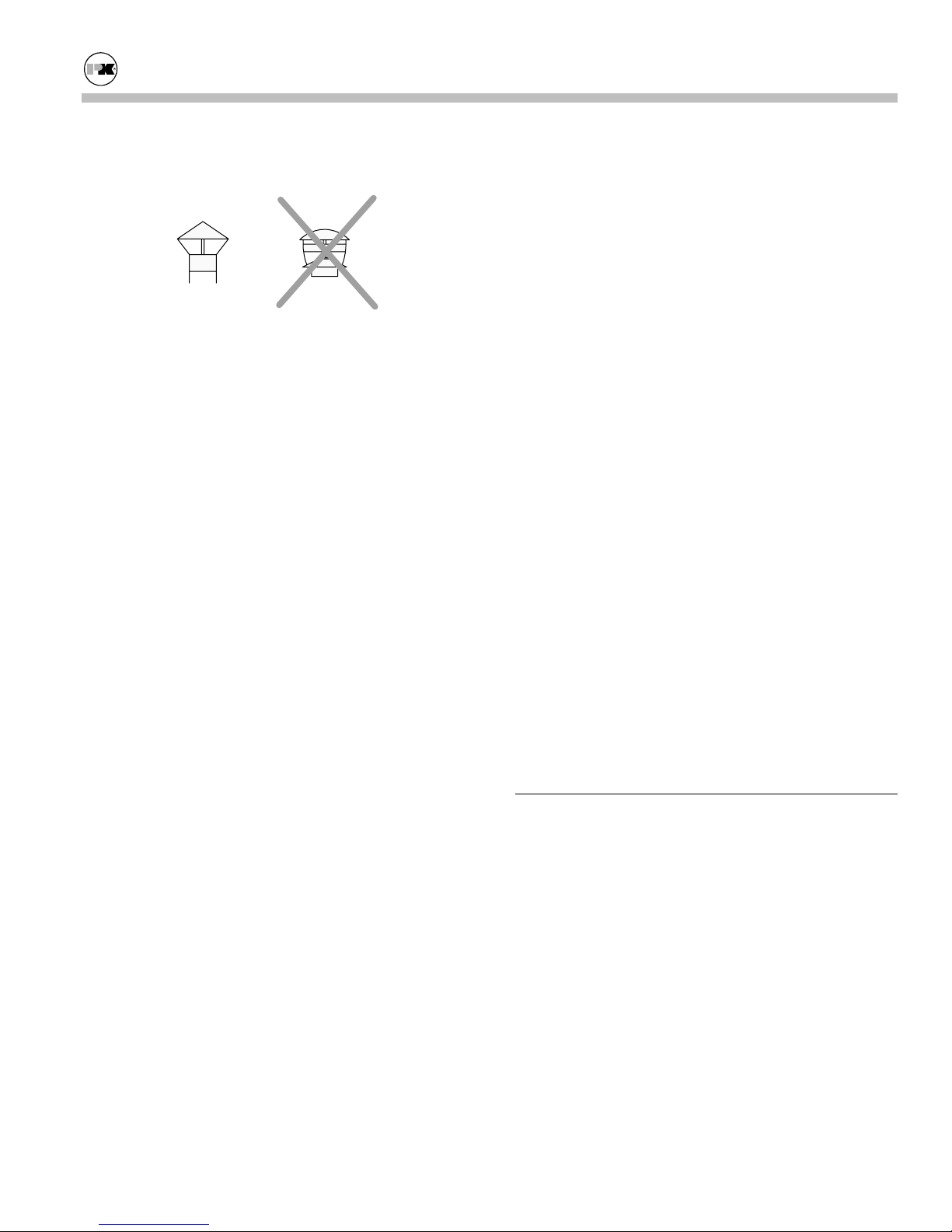
3.6.5 Vent Termination
Correct
Listed
Te rm ination
Typical Incorrect
(too restrictive)
Vent Termination
The minimum vent height above the flue outlet must
be five (5) feet and the vent should extend at least
three (3) feet above the roof, or at least two (2) feet
above the highest part of any structure within ten (10)
feet of the vent.
The vent must be provided with a weather cap of approved design and adequate capacity.
3.6.6 Removing an Existing Boiler
(from a common venting system)
When an existing boiler is removed from a common
venting system, the common venting system is likely
to be too large for proper venting of the appliances
remaining connected to it.
system. Turn on any exhaust fans, such as range
hoods and bathroom exhausts, so they will operate
at maximum speed. Do not operate a summer exhaust fan. Close fireplace dampers.
4. Place the appliance being inspected in operation.
Follow the lighting instructions. Adjust the thermostat so that the appliance will operate continuously.
5. Test for spillage at the draft hood relief opening
after 5 minutes of main burner operation. Use the
flame of a match or candle or smoke from a cigarette, cigar or pipe.
6. After it has been determined that each appliance
remaining connected to the common venting system properly vents when tested as outlined above,
return doors, windows, exhaust fans, fireplace
dampers and any other gas-burning appliance to
their previous conditions of use.
Any improper operation of the common venting system should be corrected so the installation conforms
with the National Fuel Gas Code, ANSI Z223.1.
When resizing any portion of the common venting system, the common venting system should be resized to
approach the minimum size as determined using the
appropriate tables in Part II in the National Fuel Gas
Code, ANSI Z223.1.
At the time of removal of an existing boiler, while the
other appliances remaining connected to the common
venting system are not in operation, the following
steps should be followed with each appliance remaining connected to the common venting system placed in
operation:
1. Seal any unused openings in the common venting
system.
2. Visually inspect the venting system for proper size
and horizontal pitch and determine that there is no
blockage or restriction, leakage, corrosion or other
deficiency which could cause an unsafe condition.
3. Insofar as is practical, close all building doors and
windows and all doors between the space in which
the appliances remaining connected to the common venting system are located and other spaces
of the building. Turn on clothes dryers and any
appliances not connected to the common venting
Page 9
3.7
GAS PIPING
Before making the gas hook-up, make sure the boiler
is being supplied with the type of fuel shown on the
boiler nameplate.
The boiler shall be installed such that the gas ignition
system components are protected from water (dripping, spraying, rain, etc.) during appliance operation
and service (circulator replacement, control replacement, etc.)
The gas pressure regulator supplied with the boiler is
set during a factory fire-test to provide the proper pressure to the main burner, which for natural gas is based
on 7 inches W.C. inlet pressure to the regulator (11
inches W.C. for propane). The gas train components
are designed to handle a maximum inlet pressure of 14
inches water column (1/2 psig.). If the available gas
pressure exceeds 14 inch W.C., a suitable additional
Thermific® Gas-Fired Boiler Installation
intermediate gas pressure regulator of the "lock up"
type must be provided to reduce the pressure to less
than 14 inch W.C.
WARNING!
All threaded connections must be made using a pipe
compound that is resistant to the action of liquefied
petroleum gases. Do not use Teflon tape on gas line
threads.
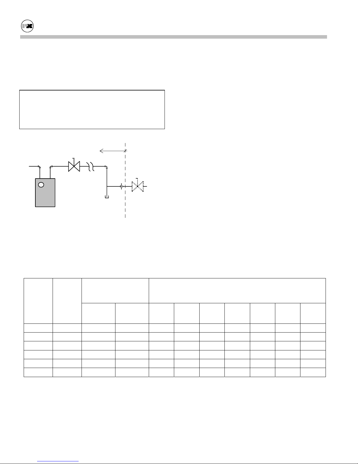
by installer
natural gas
supply
remote gas shutoff
(not supplied)
drip leg
meter
(not supplied)
union
shutoff
(on boiler)
Gas Piping
Pipe Capacity for Natural Gas
Nominal
Iron
Pipe
Size
(Inches)
Internal
Diame-
ter
(Inches)
Equivalent Pipe Length Maximum Capacity in Cubic Feet of Natural Gas per Hour
90º Ell
(Feet)
Tee
(Feet)
Note: Install a sediment trap (drip leg) and a union
connection ahead of the primary manual shutoff valve
on the boiler. Gas piping should be installed in accordance with National Fuel Gas Code, ANSI Z223.1,
latest edition, and any other local codes which may
apply; in Canada see CAN/CGA-B 149.
Note: See chart below for required pipe size, based on
overall length of pipe from meter plus equivalent
length of all fittings. Approximate sizing may be based
on 1 cubic foot of natural gas per 1,000 Btu per hour
input, i.e., 900,000 Btu per hour requires about 900
cubic feet per hour. (See Typical Boiler Operating
Conditions, Section 4.3, for more information.)
Pressure Drop of 0.5 inch Water Column/Equivalent Length of
Pipe (in feet)
20
40
60
80
100
150
200
1-1/4 1.380 3.5 6.9 950
1-1/2 1.610 4.0 8.0 1,460 990 810
2 2.067 5.2 10.3 2,750 1,900 1,520 1,300 1,150 950 950
2-1/2 2.469 6.2 12.3 4,350 3,000 2,400 2,050 1,850 1,500 1,280
3 3.068 7.7 15.3 7,700 5,300 4,300 3,700 3,250 2,650 2,280
4 4.026 10.1 20.2 15,800 15,800 8,800 7,500 6,700 5,500 4,800
Page 10
 Loading...