

Patterson-Kelley MACH C1500, MACH C2000 Installation And Owner's Manual
PATTERSON-KELLEY
MACH C1500/C2000
GAS-FIRED BOILER
LMACH- 07
C.S.A Design-Certified
Complies with ANSI Z21.13/CSA 4.9
Gas-Fired Low Pressure Steam and Hot Water
Boilers
ASME Code, Section IV
Certified by Patterson-Kelley
C.S.A Design-Certified
Complies with ANSI Z21.13/CSA 4.9
Gas-Fired Low Pressure Steam and Hot Water
Boilers
Installation Date: _______________________
100 Burson Street, P.O. Box 458,
East Stroudsburg, PA 18301
Telephone: (877) 728-5351, Facsimile: (570) 476-7247
www.pkboilers.com

MACH® Series Gas-Fired Boiler Table of Contents

MACH® Series Gas-Fired Boiler Table of Contents
1.0 INTRODUCTION ........................................1
2.0 SAFETY......................................................1
2.1 General..............................................................1
2.2 Training..............................................................1
2.3 Safety Features .................................................2
2.4 Safety Labels.....................................................2
2.5 Safety Precautions ............................................2
2.5.2 Burn, Fire, and Explosion Hazards..........2
2.5.3 Crush Hazards.........................................3
2.5.4 Chemical Hazards....................................4
2.5.5 Pressure Hazards ....................................4
2.5.6 Slip, Fall Hazards.....................................4
3.0 INSTALLATION..........................................5
3.1 Receiving and Storage......................................5
3.1.1 Initial Inspection .......................................5
3.1.2 Storage Prior to Installation......................5
3.2 Compliance with Codes.....................................5
3.3 Setup .................................................................5
3.3.1 Foundation and Placement......................5
3.3.2 Clearances...............................................6
3.4 Electrical Connections.......................................6
3.5 Combustion Air..................................................7
3.5.1 Air Inlet Requirements..............................7
3.6 Flue Venting.......................................................8
3.6.1 Barometric Damper..................................9
3.6.2 Flue Connection.......................................9
3.6.3 Required Clearances ...............................9
3.6.4 Vertical Vent Systems............................10
3.6.5 Vent Terminations..................................10
3.6.6. Direct Vent (Sealed Combustion) Systems
...................................................................
3.6.7 Sidewall Venting with Sealed Combustion11
3.6.8 Intake Duct Materials and Sizes: ...........12
3.6.9 Sealing the Intake Duct..........................12
3.6.10 Intake Duct Connection to Boiler .........12
3.6.11 Venting for Multiple Boilers..................12
11
3.6.12 Removing an Existing Boiler................12
3.7 Gas Piping.......................................................13
3.7.1 Gas Supply Piping by Installer...............15
3.8 Boiler Water Piping..........................................15
3.8.1 Piping Design.........................................15
3.8.2 Boiler Inlet and Outlet Connections.......16
3.8.3 Boiler Water Piping by Installer..............17
3.8.4 Flushing and Filling................................17
3.9 Burner and Ignition System.............................18
3.9.1 Inspection...............................................18
3.10 Pre-Start Check List ......................................18
3.11 Safety Checks ...............................................19
3.11.1 Test of Ignition Safety System.............19
3.11.2 Test of Low Water Cut-out...................19
3.11.3 Test of High-Limit Control....................19
3.11.4 Test of Gas Pressure Switch ...............19
3.12 Initial Adjustments .........................................20
3.12.1 Operating Temperature Controller.......20
3.12.2 Burner Setup...................................24
3.12.3 Gas Pressure Adjustment....................25
3.12.4 Air Flow Adjustments...........................25
3.12.5 Gas Valve Setup and Adjustment........25
4.0 OPERATION ............................................28
4.1 General............................................................28
4.1.1 Control Panel Front................................28
4.1.2 Tests ......................................................28
4.2 Normal Lighting and Shut-Down Procedures..28
4.2.1 Lighting Procedures...............................28
4.2.2 Normal Shut Down Procedures .............28
4.2.3 Emergency Shut-Off ..............................28
4.3 Typical Boiler Operating Conditions................29
5.0 MAINTENANCE.......................................30
5.1 Maintenance and Inspection Schedule ...........30
5.1.1 Daily.......................................................30
5.1.2 Weekly ...................................................30
5.1.3 Monthly (During Operation)....................30
MACH® Series Gas-Fired Boiler Table of Contents
5.1.4 Semi-Annually (required for boilers operated
year round) ................................................
5.1.5 Annually .................................................31
5.2 Cleaning the Burner.........................................31
5.3 After All Repairs or Maintenance.....................32
5.4 Sequence of Operation....................................32
5.5 Troubleshooting...............................................33
5.5.1 Manual Reset Service Codes ................37
5.5.2 Auto-reset Service Codes......................38
31
6.0 PARTS/TECHNICAL SUPPORT..............39
6.1 Schematic Diagrams ........................................39
6.2 Wiring Diagrams..............................................40
WARNING!
It is essential to read, understand, and follow the
recommendations of this manual before installing,
operating, or servicing this equipment. Failure to
do so could result in fire or explosion and serious
injury, death, and/or property damage.
The same features which permit this boiler to achieve
high-efficiency performance make it unlike most other
boilers of this general size, so it is important to
understand how this boiler operates.
WARNING
Do not store or use gasoline or other flammable
vapors or liquids in the vicinity of this or any other
appliance.
6.2.1a Terminal Block Assignments – High
Voltage Circuit (TB2).................................
6.2.1b Terminal Block Assignments – Low Voltage
Circuit (TB1) ..............................................
6.2.2 Wiring Diagram for Series C-1500/C-200042
6.3 Boiler Parts List ...............................................43
6.3.1 Main Assembly.......................................43
6.3.2 Control Panel.........................................44
6.3.3 C1500/C2000 Heat Engine....................45
6.3.4 C1500/C2000 Gas Train........................46
40
41
7.0 LIMITED WARRANTY .............................47
8.0 APPENDIX ...............................................50
WARNING!
Chemicals, fuels, or other potentially hazardous
or toxic materials must not be stored in the same
room as the boiler.
WARNING!
Installation and service must be performed by a
qualified installer or service agency who has been
trained on the Patterson-Kelley MACH Boiler.
What to do if you smell gas:
• Do not try to light any appliance.
• Do not touch any electrical switch.
• Do not use any phone in your building.
Immediately call your gas supplier from a
neighbor's phone. Follow the gas supplier's
instructions.
• If you cannot reach your gas supplier call the fire
department.
MACH® Series Gas-Fired Boiler Installation
1.0 INTRODUCTION
The P-K MACH® C1500/C2000
fully modulating using a variable speed combustion
blower, sophisticated microprocessor controls,
modulating gas safety shut off / control valves and a
unique aluminum alloy heat exchanger capable of
operating in a fully condensing mode to provide
maximum efficiency in a minimum amount of space.
The high-quality materials and thoroughly tested
design of the boiler should provide years of troublefree service if the instructions in this manual are
followed carefully.
This manual covers installation of P-K MACH
C1500/C2000 Boilers. The model numbers may be
followed by a prefix or suffix letter in some cases to
indicate special features or different options.
While details may differ slightly, basic operation is the
same for all models. Check the rating plate for correct
fuel usage and gas pressures.
The boiler is only a part of the complete heating
system. This boiler may be fully operational and yet
because of poor circulation, control, or other operating
characteristics, not deliver heat to the desired location.
Additional equipment such as temperature sensors,
pumps, flow switches, balancing valves, and check
valves will be required for satisfactory operation of
any system. Patterson-Kelley cannot be responsible
for the design or operation of such systems and a
qualified engineer or contractor must be consulted.
Gas-Fired Boilers are
2.0 SAFETY
2.1
GENERAL
The MACH C1500/C2000 gas-fired boiler must be:
• Installed, operated, and serviced in accordance
with instructions contained in this manual.
• Installed by qualified personnel in accordance with
designs prepared by qualified facility engineers
including: structural, mechanical, electrical, and
other applicable disciplines.
• Operated and serviced in accordance with a
comprehensive safety program determined and
established by the customer. Do not attempt to
operate or service until such a program has been
established.
• Operated and serviced by qualified and
knowledgeable personnel in accordance with all
applicable codes, laws, and regulations.
• The use of the term “factory-trained personnel”
throughout this manual indicates PattersonKelley trained on this specific piece of
equipment.
Note: Each safety device must be maintained and
checked per the recommended schedule; refer to
Section 5.1 of this manual.
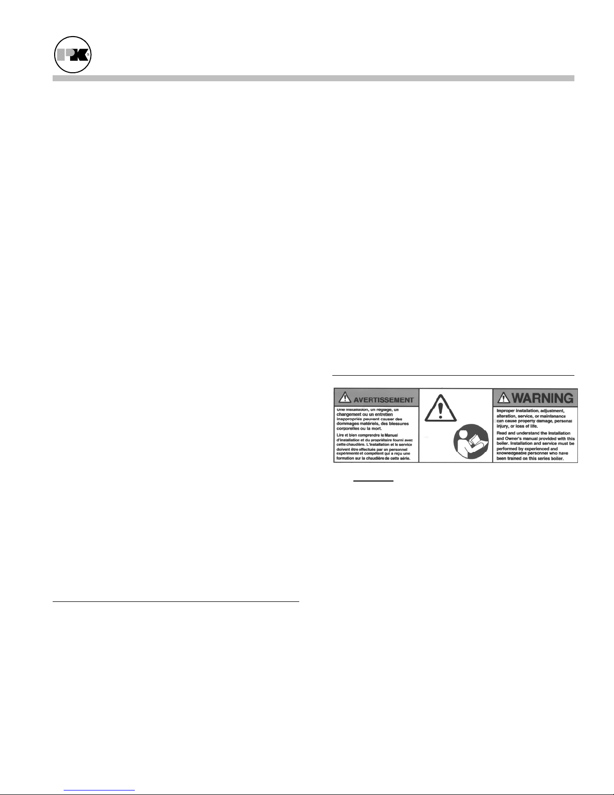
TRAINING
2.2
It is essential
to read, understand, and follow the
recommendations of this manual before installing,
operating, or servicing this equipment. Failure to do
so could result in fire or explosion and serious injury,
death, and/or property damage.
Proper training is the best protection against
accidents. Operating and service personnel must be
thoroughly familiar with the basic construction of the
P-K MACH C1500/C2000
boiler, the use and
locations of the controls, the operation of the boiler,
adjustment of its various mechanisms, and all
applicable safety precautions. If any of the
provisions of this manual are not fully and completely
understood, contact the Patterson-Kelley Sales
Department toll-free at (877) 728-5351 for assistance.
Page 1
MACH® Series Gas-Fired Boiler Installation
2.3 SAFETY FEATURES
It is the responsibility of the customer to maintain the
safety features, such as but not limited to: guards,
safety labels, safety controls, interlocks, lockout
devices, in place and operable.
SAFETY LABELS
2.4
The following words are used in this manual to denote the degree of seriousness of the individual
hazards.
DANGER – Used to indicate an imminently hazardous
situation which, if not avoided, will result in death or
serious injury. This signal word is to be limited to the
most extreme conditions.
WARNING – Indicates a potentially hazardous
situation which, if not avoided, could result in death or
serious injury.
CAUTION – Used to indicate a potentially hazardous
situation which, if not avoided, may result in minor or
moderate injury.
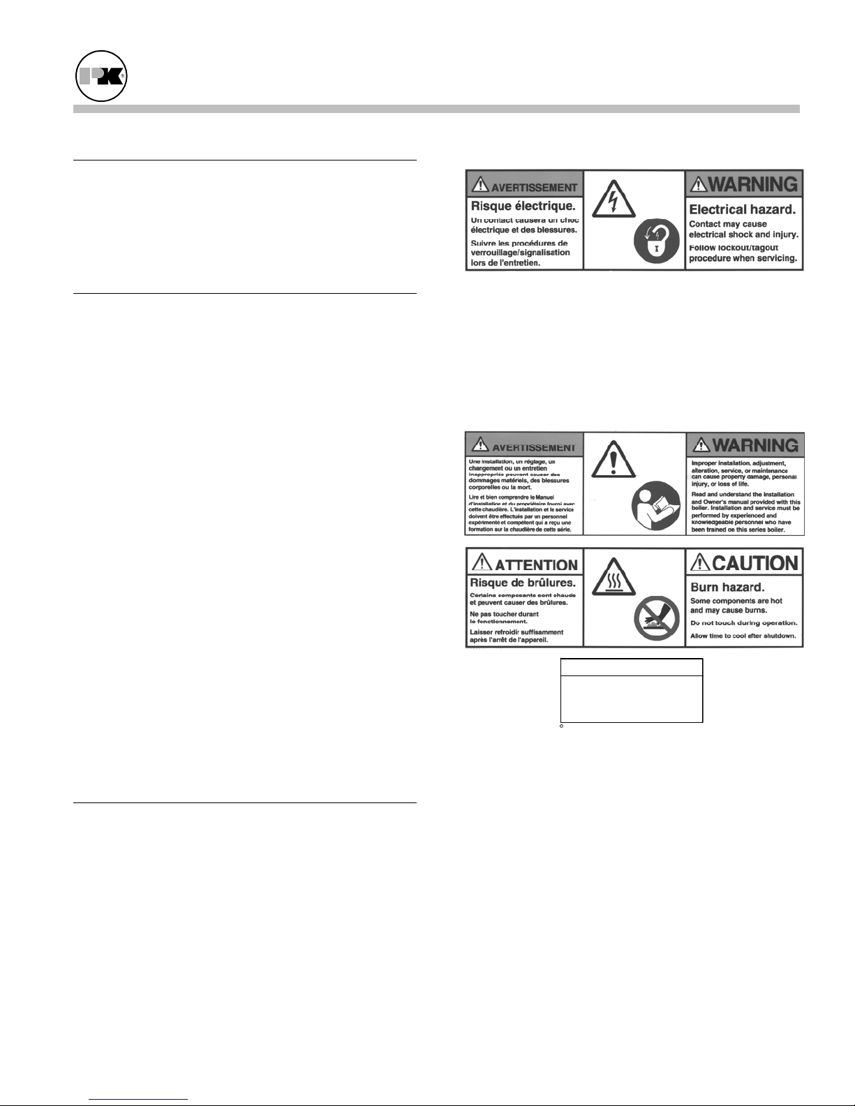
2.5.1 Electrical Hazards
• Shock hazard! Properly lockout/tagout the
electrical service and all other energy sources
before working on or near the boiler.
• Shock hazard! Do not spray water directly on
this boiler or on any electrical components.
2.5.2 Burn, Fire, and Explosion Hazards
NOTICE/NOTE - NOTICE is the preferred signal
word to address practices not related to personal
injury. The safety alert symbol is not used with this
signal word.
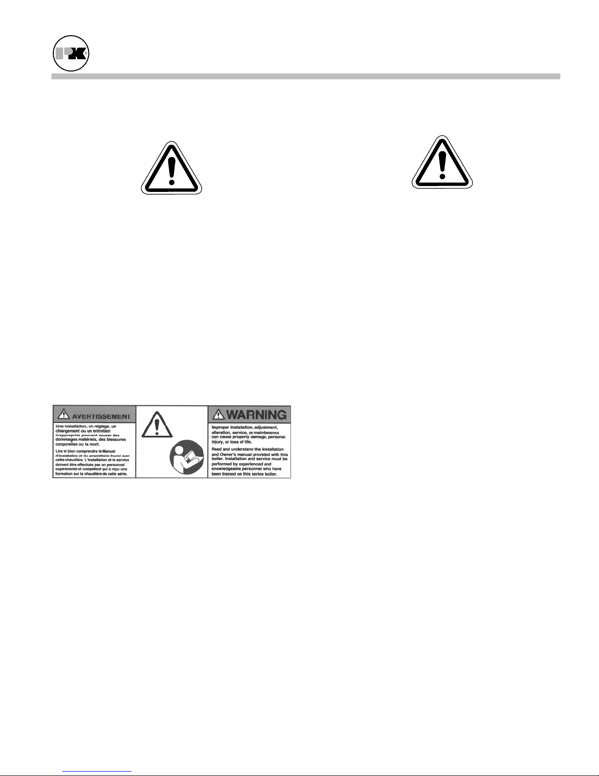
The safety labels shown below are affixed to your
boiler. Although the labels are of high quality, they
may become dislodged or unreadable over time.
Contact Patterson-Kelley toll-free at (877) 728-5351
for replacement labels.
SAFETY PRECAUTIONS
2.5
Provide a suitable location for the boiler, away from
normal personnel traffic, with adequate working space,
adequate clearances, proper ventilation and lighting,
with a structure sufficiently strong and rigid to support
the weight of the boiler, all piping, and accessories.
NOTE
When opening leak test valves,
always follow instructions in
operation and safety manual.
c
1998 HCS, Inc. 800-748-0241
• Burn, fire, and explosion hazards! Installation
must be in strict conformance to all applicable
codes and standards including NFPA 54, ANSI
Z223.1 and CSA B.149. Install all required vent
lines for gas devices. Refer to Section 3.7.1.
• Hazard from incorrect fuels! Possible fire,
explosion, overheating, and damage. Do not use
any fuels except the design fuels for the unit.
• Overfire hazards! High pressure in gas supply
could result in overfiring of this or other devices
supplied from the same source.
Reorder No. 8032-01NHPK
Page 2
• Fire and explosion hazards! Close the main gas
shutoff before servicing boiler.
MACH® Series Gas-Fired Boiler Installation
• Fire and explosion hazards! Do not store or use
gasoline or other flammable vapors or liquids in
the vicinity of this or any other gas fired appliance.
• Burn hazard! Possible hot surfaces. Do not touch
gas vent during firing operation. Use only factory
recommended vent components.
• Burn hazard! Pipes, vents, and boiler components
could be hot. Do not touch piping or stack
surfaces during operation or immediately after
shutdown of the boiler.
• Burn hazard! Hot fluids. Use caution when
servicing or draining boiler.
• Fire and explosion hazards! Use caution when
servicing burner. Propane (LPG) is heavier than
air and may linger in the combustion chamber,
vent lines, or elsewhere.
• Gas leak hazard! Make sure the burner is installed
correctly and blower/transition is securely fastened
following any maintenance performed on them.
These connections may leak gas if assembled
incorrectly.
• Gas leak hazard! All threaded gas connections
must be made using a pipe compound that is
resistant to liquefied petroleum gas. Do not use
Teflon™ tape on threaded gas piping.
• Gas leak hazard! Check entire gas train for leaks
after installation. If there is a smell of gas, shut
down the boiler and obtain immediate assistance
from trained service personnel and/or your local
fire department.
• Overfire and underfire hazards! Possible fire,
explosion, overheating, and component failure.
Do not attempt to adjust firing rate of the boiler.
The firing rate must be adjusted only by factory
trained personnel.
2.5.3 Crush Hazards
General Warning
• Lifting hazards! Use properly rated lifting
equipment to lift and position the boiler. The
load is unbalanced. Test balance before lifting 3
ft. above the floor. Do not allow personnel
beneath the lifted load. Refer to approximate
weights in the table below:
Boiler Size Weight in Pounds
C1500 1200
C2000 1400
• Bump hazard from overhead ductwork and
piping. Install components with adequate vertical
clearance.
• Overfire hazard! Possible fire and explosion from
excess gas pressure. Make sure that gas inlet
pressure does not exceed 14 inches W.C.
• Overfire hazard! Possible fire and explosion.
Possible malfunction of regulators and/or gas
safety shut off / control valves. Maintain all gas
train components in good condition. Do not alter
wiring connections. Annual inspection by factorytrained personnel for proper set-up and operation
is recommended.
Page 3
MACH® Series Gas-Fired Boiler Installation
2.5.4 Chemical Hazards
General Warning
• Chemical hazards from cleaning products. Use
caution when cleaning the system. The use of
professional assistance is recommended. Use safe
procedures for the disposal of all cleaning
solutions.
• Combustion Condensate – a pH of approximately
3 to 5 can be expected. Use PVC or CPVC piping.
Collection and disposal must be in accordance
with all applicable regulations.
2.5.5 Pressure Hazards
2.5.6 Slip, Fall Hazards
General Warning
• Tripping hazard! Do not install piping on floor
surfaces. Maintain clear path around boiler.
• Slip and fall hazard! Use drip pan to catch water
while draining the boiler. Maintain dry floor
surfaces.
• Slip and fall hazard! Do not locate intake or
exhaust terminations directly above a walkway;
dripping of condensation can cause icing of the
walking surface.
• Fall hazard! Do not stand on any part of the
boiler.
• Catch hazard! Do not wear rings, jewelry, long
hair, loose clothing while working on the boiler.
• Pressure hazard! Hot fluids. Install isolation
valves on boiler water inlet and outlet. Make sure
isolation valves are closed before servicing boiler.
• Pressure hazard! Hot fluids. Annually test safety
relief valve for proper operation. Do not operate
boiler with faulty relief valve.
Page 4
MACH® Series Gas-Fired Boiler Installation
3.0 INSTALLATION
WARNING!
Installation and service must be performed by a
qualified installer, service agency, or gas supplier.
RECEIVING AND STORAGE
3.1
3.1.1 Initial Inspection
Upon receiving the boiler, inspect it for signs of
shipping damage. Since some damage may be hidden,
unpack the boiler, open the front and side doors and
inspect the internals of the boiler.
Verify that the total number of pieces shown on the
packing slip agrees with those actually received.
Important: Note any damage, suspected potential
damage, or shortage of materials on the freight bill and
immediately notify the carrier. File all claims for
shortage or damage with the carrier. Claims for
hidden damages must be filed with your carrier within
7 days. The boiler carton is equipped with a “Tip (N)
Tell”. If "Tip (N) Tell” arrow point is blue, or if the
“Tip (N) Tell” is missing, it is likely that the package
has been on its side or tipped over in transit.
3.1.2 Storage Prior to Installation
If the boiler is not installed immediately, it must be
stored in a location adequately protected from the
weather, preferably indoors. If this is not possible,
then it should remain in the shipping container and be
covered by a tarpaulin or other waterproof covering.
Note: controls and other equipment that are
damaged or fail due to weather exposure are not
covered by warranty.
COMPLIANCE WITH CODES
3.2
The P-K MACH C1500/C2000 Boiler with standard
components and options complies with American
National Standard/CSA Standard ANSI Z21.13/CSA
4.9, latest edition, Gas-Fired Low Pressure Steam and
Hot Water Boilers.
The heat exchanger is constructed and stamped in
accordance with ASME Boiler and Pressure Vessel
Code, Section IV for 100 psig maximum operating
pressure and/or 200º F maximum temperature.
Installation of the boiler must comply with the
requirements of all national, state and local codes
established by the authorities having jurisdiction.
Authorities having jurisdiction should be consulted
before installations are made.
Within the US, and in the absence of such local
requirements, this boiler should be installed using the
National Fuel Gas Code, ANSI Z223.1/NFPA 54,
latest edition.
In Canada, the equipment shall be installed in
accordance with the current Installation Code for Gas
Burning Appliances and Equipment, CAN/CSAB149, latest edition and applicable Provincial
Regulations for the class, which should be carefully
followed in all cases.
Where required by local codes, the installation must
conform to American Society of Mechanical
Engineers Safety Code for Controls and Safety
Devices for Automatically Fired Boilers (ASME
CSD-1).
In the Commonwealth of Massachusetts see the
Supplement for Massachusetts.
SETUP
3.3
3.3.1 Foundation and Placement
Provide a firm, level foundation, preferably of
concrete.
WARNING! The wheels provided with this boiler
are for positioning purposes only. When positioning
this boiler, maintain positive control of it at all times.
Do not attempt to move the boiler on surfaces that are
not level. Failure to heed this warning could result in
personal injury or death.
Lifting the front of the boiler slightly will allow the
boiler to be rolled off the shipping skid onto the
concrete foundation. Once in position, the wheel
Page 5
MACH® Series Gas-Fired Boiler Installation
bolts may be removed allowing the wheels to recess up
into the boiler. The base will sit flat on the provided
foundation. If the boiler is to be pulled out for
maintenance, the wheels may be left attached.
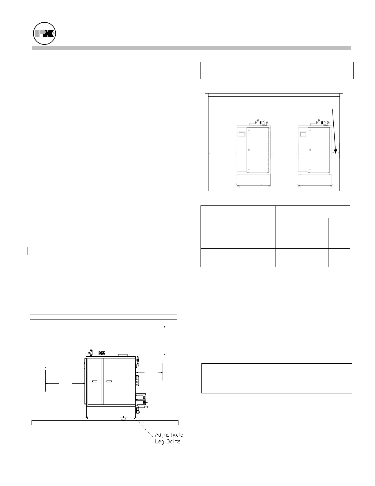
The boiler must be level to function properly. To
assist in leveling the boiler, the four (4) adjustable leg
bolts (1/2"- 13 NC) must be installed. The adjustable
legs are also necessary to prevent distortion of the
cabinet, (twisting, etc.) in addition to leveling.
Additionally there are three holes in the front and rear
of the base that may be used for seismic anchoring.
Note: The boiler may be installed on a combustible
floor; however, the boiler must never be installed on
carpeting.
3.3.2 Clearances
If the boiler is to be installed near combustible
surfaces, the minimum clearances shown in the
pictures and table below must be maintained.
Failure to provide for the service access clearances,
even with non-combustible surfaces, may cause future
problems servicing the boiler.
Maintain a clearance from the vent to combustible
surfaces of 18” or as specified in the vent
manufacturer’s listed installation instructions.
The boiler must be installed in a space large in
comparison to the boiler as described in the National
Fuel Gas Code, ANSI Z223.1, latest edition.
C
A
B
Minimum Clearances from Adjacent Walls,
Ceiling, and Obstructions (shown above &below)
D
Combustible Surfaces
Minimum Clearances
Recommended Service
Clearances
D
D
Dimensions (inches) Type of Surface
A B C† D
18 18 18 18
12*
30
12 18**
† "C" Space required for pipes, ducts, etc. in this
area above the boiler.
* Clearance depends upon exhaust vent configuration.
** Service access is required on left side of boiler to
facilitate boiler maintenance. Minimum 2” clearance
is required on right side. Do not
put pipes, ducts,
vents, etc in this space. Electrical conduit must be
installed vertically so that the side doors can be
opened.
CAUTION!
Bumping hazard from overhead ducts! Install all
components with adequate vertical clearances.
ELECTRICAL CONNECTIONS
3.4
The boiler is wired for 120 volts, single phase, 60
hertz. The total operating amperage is indicated on
the rating nameplate. Each C1500/C2000 boiler
Page 6
MACH® Series Gas-Fired Boiler Installation
requires less than 15 amps. Before starting the boiler,
check to ensure that the proper electrical service is
connected to the boiler.
An external electrical disconnect (not supplied with
the boiler) is required. The boiler electrical service
must be installed and grounded in accordance with
local codes or in the absence of such requirements, in
the U.S. with National Electrical Codes, ANSI/NFPA
No. 70 latest edition or, in Canada, to the Canadian
Electrical Code, Part I, CSA C22.1, latest edition.
Conduit must be installed vertically so that the side
doors can be opened.
Note: A dedicated earth ground (green wire) and
neutral is required to avoid nuisance shutdowns. Do
not ground through the conduit. It is also important
that proper polarity be maintained.
Note: Refer to electrical wiring section for terminal
block assignments (Section 6.1).
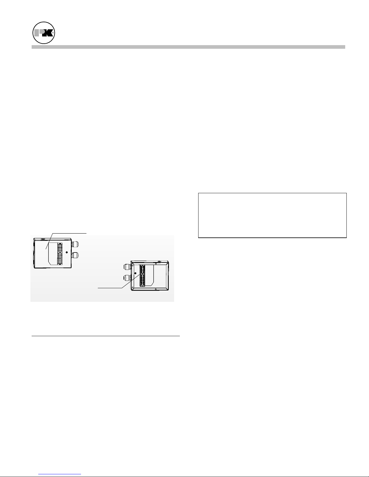
120 Volt
Junction Box
Low Voltage
Junction Box
Customer Connections for the Boiler
Viewed from Front of Boiler.
COMBUSTION AIR
3.5
Note: Additional information is contained in the
venting supplement “MACH-07VG”.
Combustion air must be free from dust, lint, etc. The
presence of such materials in the air supplied to the
burner could cause nuisance "Low Air" shutdowns or
premature burner failure. The boiler should not be
operated during construction while the possibility of
drywall dust, demolition dust, etc. exists.
The combustion air supply must be completely free of
chemical fumes which may be corrosive when burned
in the boiler. Common chemicals which must be
avoided are fluorocarbons and other halogenated
compounds, most commonly present as refrigerants
or solvents, such as freon, trichlorethylene,
perchlorethylene, chlorine, etc. These chemicals,
when burned, form acids which quickly attack the
boiler and the boiler stack. The result is improper
combustion and premature boiler failure.
Provisions for combustion and ventilation air must be
in accordance with Section 9.3, Air for Combustion
and Ventilation, of the National Fuel Gas Code,
ANSI Z223.1, latest edition, or applicable provisions
of the local building codes. In Canada, combustion
air openings shall comply with CSA B.149
Installation Code.
3.5.1 Air Inlet Requirements
Caution.
The boiler room should not be at a negative
pressure. Particular care should be taken when
exhaust fans, compressors, air-handling units or
other equipment may rob air from the boiler.
Combustion air may be supplied from within the
building or from outdoors. The minimum required
volume of the mechanical room and connected spaces
is 50 cu. Ft. per 1000 Btu/hr (4.8 m
3
/kW). If this
volume is not available, air must be taken from
outdoors.
When air is supplied from inside the building, the
total required volume shall be the sum of the required
volume for all the appliances located in the
mechanical room. Adjacent rooms furnished with
fixed openings communicating directly with the
mechanical room are considered part of the required
volume.
Openings used to connect indoor spaces to obtain the
required minimum volume shall be sized as follows:
• When rooms are on the same floor, each opening
shall have an area equal to 1 square inch for each
1000 Btu/hr (2200 mm
2
/ kW) of installed
appliance input capacity, but not less than 100
square
inches. One opening should be less than
12 inches above the floor and the other less than
12 inches below the ceiling. The minimum
dimension of air openings shall be 3 inches.
Page 7
MACH® Series Gas-Fired Boiler Installation
• When rooms are on different floors, each opening
shall have an area equal to 2 square inches for
each 1000 Btu/hr (4400 mm
2
/ kW) of installed
appliance input capacity.
When combustion air is supplied from outside the
building, the boiler room shall be provided with one or
two openings to ensure adequate combustion air and
proper ventilation.
When using one permanent opening, the opening shall
commence within 12 inches of the ceiling and shall
communicate directly with the outdoors or through a
vertical or horizontal duct that communicates to the
outdoors.
Minimum free area of the opening is;
• 1 square inch for each 3000 Btu/hr (700 mm
2
/
kW) of installed appliance input capacity, and
• not less than the sum of the areas of all vent
connectors in the room.
When using two permanent openings, one opening
shall be less than 12 inches above the floor and the
other less than 12 inches below the ceiling, preferably
on opposite walls. The openings shall communicate
directly, or by way of ducts, with free outdoor air.
Minimum net free area of the openings shall be
calculated in accordance with the following:
• When air is taken directly from outside the
building, each opening (minimum of two, as
outlined above), 1 square inch for each 4,000 Btu
per hour of total boiler input is required.
• When air is taken from the outdoors through a
vertical duct, 1 square inch per 4,000 Btu per hour
of total boiler input is required.
• When air is taken from the outdoors through a
horizontal duct , 1 square inch per 2,000 Btu per
hour of total boiler input is required.
NOTE:
1. The required size of openings for combustion,
ventilation and dilution air shall be based on the
net free area of the opening.
2. Screens shall be not smaller than ¼”.
3. Motorized louvers shall be interlocked with the
appliance so that they are proven open prior to
main burner ignition and operation.
FLUE VENTING
3.6
Note: Additional information is contained in the
venting supplement “MACH-07VG”.
Caution!
All boiler venting systems should be designed by
a qualified professional engineer experienced in
venting system design. The information
contained herein should be used as a guide only
and is not intended to be used in lieu of qualified
technical expertise.
This boiler is Category IV (condensing – positive
pressure) as it is defined in ANSI Z21.13/CSA 4.9,
latest edition. This boiler is not certified for use
with Type "B" vent.
The vent material must be :
• AL29-4C Stainless Steel Vent Systems
listed and labeled to UL1738 Venting
Systems for Gas-Burning Appliances,
Categories II, III, and IV
• 316L Stainless Steel where certified
and warranted by the vent
manufacturer for venting of Category
IV appliances
Vent installations shall be in accordance with Part 12,
Venting of Equipment, of the National Fuel Gas Code,
ANSI Z223.1 or Part 8, Venting Systems and Air
Supply for Appliances of the Natural Gas and Propane
Installation Code CAN/CSA-B149 current revision,
or applicable provisions of the local building codes.
The vent must be sized in accordance with the
ASHRAE Systems and Equipment
handbook,
Chapter 30 or according to the vent manufacturer’s
recommendations. When using manufactured vent
systems; consult your vent supplier for correct sizing
and structural support requirements.
Page 8
MACH® Series Gas-Fired Boiler Installation
Vent design calculations should be based on a
maximum of 0.44" W.C. combined frictional
resistance across the air inlet duct and the stack, with a
stack temperature of 185° F (gross) and a CO
level of
2
9.2% on natural gas. Consult your local vent
manufacturer for proper sizing.
3.6.1 Barometric Damper
WARNING!
Do not use a barometric damper with this
boiler. (This is a positive pressure system;
combustion gas may leak into the room.)
3.6.2 Flue Connection
Note: Additional information is contained in the
venting supplement “MACH-07VG”.
The outlet of the boiler is a metric female pipe with a
gasket. It requires a male adapter that is 9.79” OD as
the mating piece. This adapter should be obtained
from the venting manufacturer and will be specific for
this boiler. The connection from the boiler to the stack
should be as direct as possible and any horizontal
breaching should have an upward slope at least 1/4
inch per linear foot.
This boiler should not be connected into any portion
of another mechanical draft system without
consulting your venting manufacturer. This boiler
shall not be connected to any part of a vent system
serving a Category I appliance, nor shall a Category I
appliance be connected to any part of the vent system
serving this appliance.
Note: If the vent is erected vertically directly from
the boiler outlet, make sure that the weight of the vent
is not supported by the boiler vent collar. The
collar is not designed to support the weight of the
vent. Structural support and spacing from
combustible surfaces must be in accordance with the
vent manufacturer's requirements.
3.6.3 Required Clearances
Provide clearances between combustion air intake,
exhaust vent, roof and wall surfaces, doors and
window, and snow line as shown in the following
diagrams. All dimensions should take into account
the snow line for the installation area.
WARNING!
Do not locate intake or exhaust terminations
directly above a walkway; dripping of condensation can cause icing of the walking surface.
Page 9

MACH® Series Gas-Fired Boiler Installation
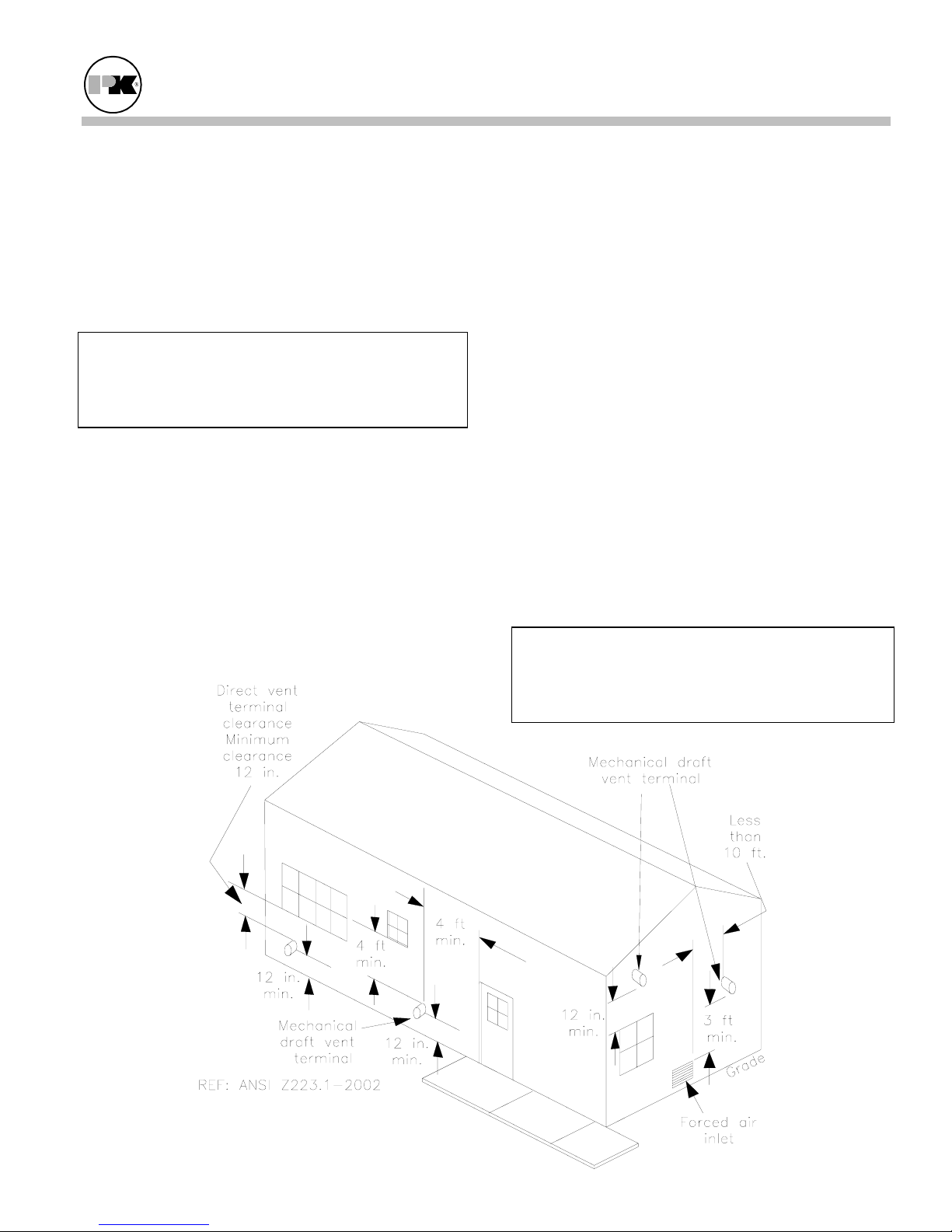
3.6.4 Vertical Vent Systems
The following termination clearance requirements are
for conventional, non-direct vent installations.
The vent system shall terminate at least 3 ft above a
forced air inlet within 10 feet horizontally.
The vent system shall terminate at least 4 ft below, 4 ft
horizontally from or 1 ft above any door, operable
window or gravity inlet into any building. The bottom
of the vent terminal shall be at least 12 in. above grade
or highest expected snow line (if applicable).
The boiler vent connection is vertical and may be
reduced. The stack size may be a nominal ten (10”),
eight (8”), or six (6”), so long as the combined air and
stack pressure resistance of 0.44” total is not exceeded.
When using 10” or 8” stack, a sealed air inlet duct may
also be used. When using 6” stack, the only allowable
configuration is vertical without offsets (elbows, tees,
etc.) which results in 0.44” or less of resistance and
without a sealed air inlet.
Combustion Air
Inlet of *another*
appliance
10' min*.
3' min.
Boiler Flue
Gas Outlet
Typical through the roof venting.
3.6.5 Vent Terminations
Vent Supports
4' min above
snow line
No rain cap
required,
or Tee.
Vertical Vent Termination Details
The vent should extend at least four (4) feet above the
roof, or at least two (2) feet above the highest part of
any structure within ten (10) feet of the vent.
To prevent the possible re-circulation of flue gases, the vent designer must take into consideration such things as
prevailing winds, eddy zones, building configurations, etc. Patterson-Kelley Co. can not be responsible for the
effects such adverse conditions may have on the operation of the boilers. Dimensions listed above or those
illustrated are minimum, and may or may not be sufficient for conditions at a specific job site.
A tee must be of approved design and adequate capacity.
The installation of a bird screen on the vent termination is recommended.
A rain cap is not
recommended for the vent.
Page 10
MACH® Series Gas-Fired Boiler Installation
3.6.6. Direct Vent (Sealed Combustion)
Systems
The vent terminal shall be located at least 12 in. from
any air opening into a building. The bottom of the
vent terminal shall be at least 12 in. above grade. Both
the vent and air intake terminals must be at least 12 in.
above the highest expected snow line.
Through the wall terminations shall not terminate over
public walkways. Maintain a minimum clearance of 4
ft (1.22 m) horizontally from any electric of gas meter,
regulator or relief equipment.
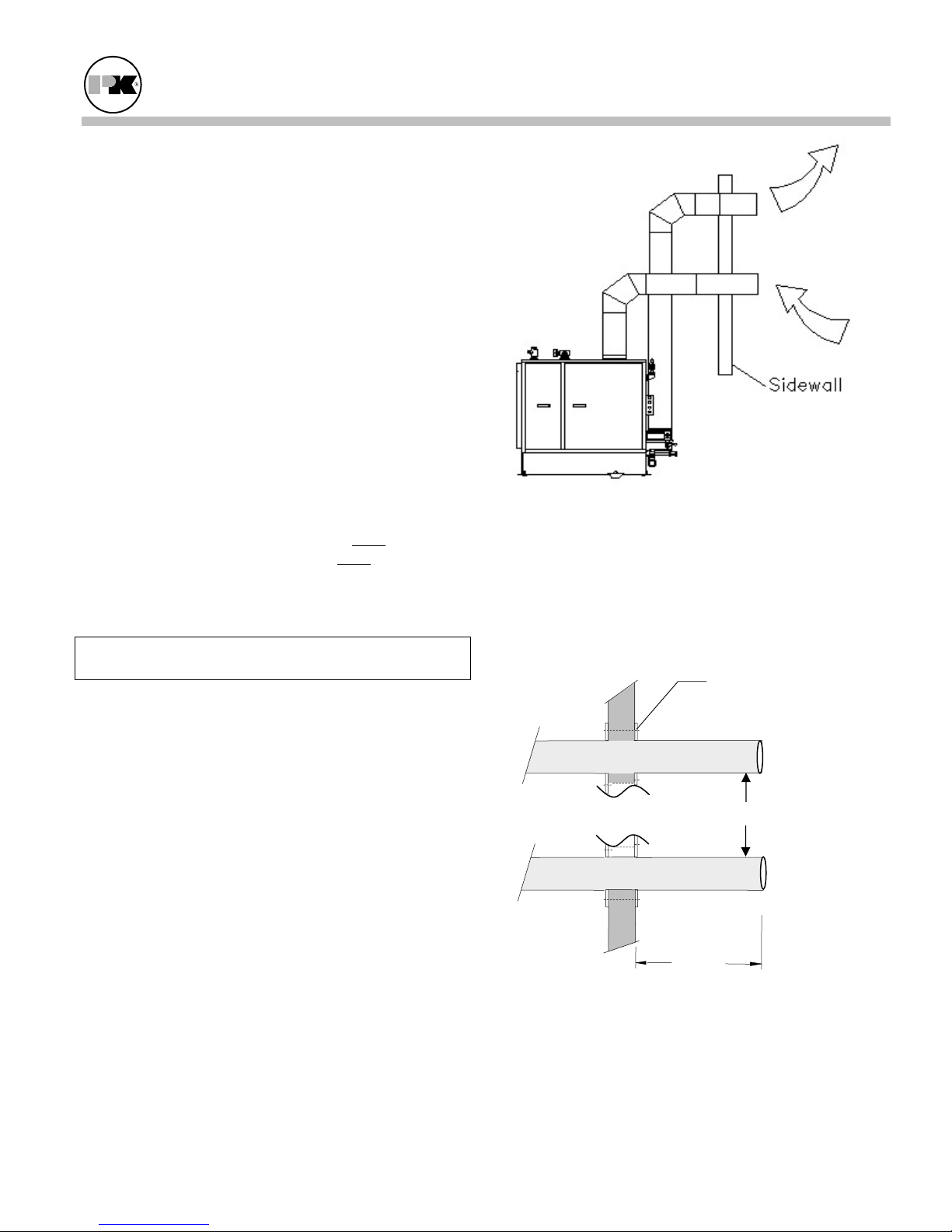
3.6.7 Sidewall Venting with Sealed
Combustion
The MACH C1500/C2000 Boilers are certified for
direct sidewall venting with a sidewall air inlet only.
Both the air inlet and the exhaust vent must
on the same wall of the building and must
terminate
utilize the
same type of termination fitting with the same
orientation. Allowable termination fittings are: 90°
elbows, tees, or straight vents.
Do not install this boiler with sidewall vent and room
air inlet!
The air inlet and vent must be sized so that the total
pressure loss for the combined inlet and vent ducts
does not exceed 0.44” w.c.. For example, if the inlet
air duct loss is 0.2” w.c., the vent duct loss cannot
exceed 0.24 “w.c.. The vent should be sized using a
gross vent temperature of 185°F, a CO2 level of 9.2%
and the residual vent pressure loss as indicated above.
The air inlet duct should be sized as indicated in
paragraph 3.6.8.
Typical
Sidewall
venting.
Vent Installation Details
This Installation must conform to the vent
manufacturer's instructions in all respects including
joining, clearances, fastening, fire-stopping, and other
matters.
Vent Manufacturers
Wall Penetration Kit
3’ min.
Page 11
12" min.
Sidewall Penetration Detail
MACH® Series Gas-Fired Boiler Installation
3.6.8 Intake Duct Materials and Sizes:
Material: PVC, CPVC, single wall galvanized steel, or
other suitable materials.
The intake duct must be sized for a pressure drop as
indicated in paragraph 3.6.7 and for the SCFM as
specified below.
Boiler Size Required SCFM
1500 350
2000 467
The installation of a bird screen on the intake
termination is recommended. Ensure that the screen
does not become blocked with snow, ice, etc.
3.6.9 Sealing the Intake Duct
Proper sealing of the intake ductwork is necessary to
prevent infiltration of air from conditioned space.
Joints in PVC or CPVC must be cemented. For
galvanized duct, wrap each joint and seam with
adhesive aluminum tape.
3.6.10 Intake Duct Connection to Boiler
Connect the air supply duct to the 10” OD collar on
the top of the boiler. Fasten the duct to the collar with
sheet metal screws at 90º angles. Seal the joint.
3.6.11 Venting for Multiple Boilers
The venting instructions in this manual apply to a
single boiler.
Venting systems for multiple boilers must be
designed by qualified professionals and verified by
the stack manufacturer. The venting system must
prevent backflow of exhaust gas through idle
boilers which are not operating.
3.6.12 Removing an Existing Boiler
(from a common venting system)
When an existing boiler is removed from a common
venting system, the common venting system is likely
to be too large for proper venting of the appliances
remaining connected to it.
At the time of removal of an existing boiler, while the
other appliances remaining connected to the common
venting system are not in operation, the following
steps should be followed with each appliance
remaining connected to the common venting system
placed in operation:
1. Seal any unused openings in the common venting
system.
2. Visually inspect the venting system for proper
size and horizontal pitch and determine that there
is no blockage or restriction, leakage, corrosion
or other deficiency which could cause an unsafe
condition.
3. Insofar as is practical, close all building doors
and windows and all doors between the space in
which the appliances remaining connected to the
common venting system are located and other
spaces of the building. Turn on clothes dryers
and any appliances not connected to the common
venting system. Turn on any exhaust fans, such
as range hoods and bathroom exhausts, so they
will operate at maximum speed. Do not operate a
summer exhaust fan. Close fireplace dampers.
4. Place the appliance being inspected in operation.
Follow the lighting instructions. Adjust the
thermostat so that the appliance will operate
continuously.
5. Test for spillage at the draft hood relief opening
after 5 minutes of main burner operation. Use the
flame of a match or candle or smoke from a
cigarette, cigar or pipe.
6. After it has been determined that each appliance
remaining connected to the common venting
system properly vents when tested as outlined
above, return doors, windows, exhaust fans,
fireplace dampers and any other gas-burning
appliance to their previous conditions of use.
Any improper operation of the common venting
system should be corrected so the installation
conforms with the National Fuel Gas Code, ANSI
Z223.1 and CSA B149 Installation Code. When
resizing any portion of the common venting system,
the common vent system should be resized to
approach the minimum size as determined using the
appropriate tables.
Page 12
 Loading...