

4264-A
V95100137
Voice Synthesized Horn Speaker and Rotating Light
Instruction Manual
TYPE : RT-VF
Thank you for purchasing the Voice Synthesized Horn Speaker and Rotating Light
Combination for you application. Please read these instructions carefully before
installation, maintenance and repair. Store this manual in a safe place for future
reference. If you have any questions regarding this product, please contact our
PATLITE Sales Representatives.
Notice for Safe Operation
In order to prevent any damage to the user and other personnel or to assets, note the
following:
■
The warning indications are divided into the following classes according to the degree of danger
or damage incurred when the warning is not taken into consideration and the product is not
correctly used.
Warning
Caution
PLEASE
NOTE
1. To operate this product properly, observe the following:
Warning
● Be sure the power is disconnected before wiring or installing this product. Possibility of
electric shock may occur.
●
Do not dissasemble or modify this product. Possibility of fire or electric shock may occur. If
repair is needed, refer to [8. Before Requesting Repair]. For questions concerning our
product or for when repair is necessary, refer to the end of this document for contacting your
nearest PATLITE Sales Representative.
● Be carefull not to miswire this product. Possible miswiring can cause product failure or fire.
● Be sure to stay within the operating voltage range. Possibility of fire, failure or malfunction
may occur.
● Request the installation and wiring be accompanied by a professional contractor. Possiblility
of fire, electric shock or falling from high places may result.
Caution
● To protect the power supply and other internal circuitry, be sure to connect an external fuse.
● Do not use bulbs other than the type specified in [9. Specifications] or what is indicated on the
name plate. Possibility of failure or product damage due to fire may occur.
● Do not operate with the globe removed. Possible burns from the heat of the bulb or injury
from the mirror may occur.
Contrary to Warnings and Cautions indicated by this document, product failure due to mishandling,
dissasembly, modifications or natural disasters, etc. is not covered by any Warranty. Moreover,
avoid any applications outside those indicated in this document.
PLEASE
● Do not use in an environment exposing strong radio waves or inductance noise. Noise may
be induced from the speaker horn causing malfunction or failure.
● Do not use in an environment where corrosive gas is present. Possible cause of failure may
occur.
● To prevent damage from static electricity, touch hands or other body parts to metals or an
earth ground to discharge the body from static charge before handling static sensitive parts,
such as the SD Card.
● Use the recommended torque when attaching parts for installation, etc.
● When this product is used for security purposes, it should be inspected daily. In case a
malfunction should occur, it is recommended that you use this product together with other
security products.
● Do not operate with the globe removed or broken. Water or dust entering the product may
cause damage.
- Caution on copyright Work that was recorded or copied from music CDs or other media used in public
places may infringe upon copyrights and law enforcement may be imposed.
When using a work that was recorded or copied from music CDs or other media, be
sure to obtain permission from the author.
In addition, copyright of audio/music data distributed or sold by PATLITE Corporation
belongs to PATLITE.
It is strictly prohibited to copy/reprint whole or partial contents of audio/music data
belonging to PATLITE Corporation, or to transfer/sell such material on computer
networks etc., without permission of the rightful holder.
Indicates an imminently dangerous condition : failure to follow the instructions may
lead to death or serious injury.
Indicates a potentially dangerous condition: failure to follow the instructions may
lead to slight injury or property damage.
Indicates something to observe before using this product. The disregard to this
indication may lead to product malfunction or failure.
Notice regarding supplementary information or convenient explanation is
indicated.
2. Model Number Configuration
RT - 100 V F UL - R
Rated Voltage
24 :D C 24 V
100 :A C 10 0V
Sound Type
V :Voice Synthesis
Standard
UL:UL standard
(only model of 24V DC)
200 :A C 20 0V
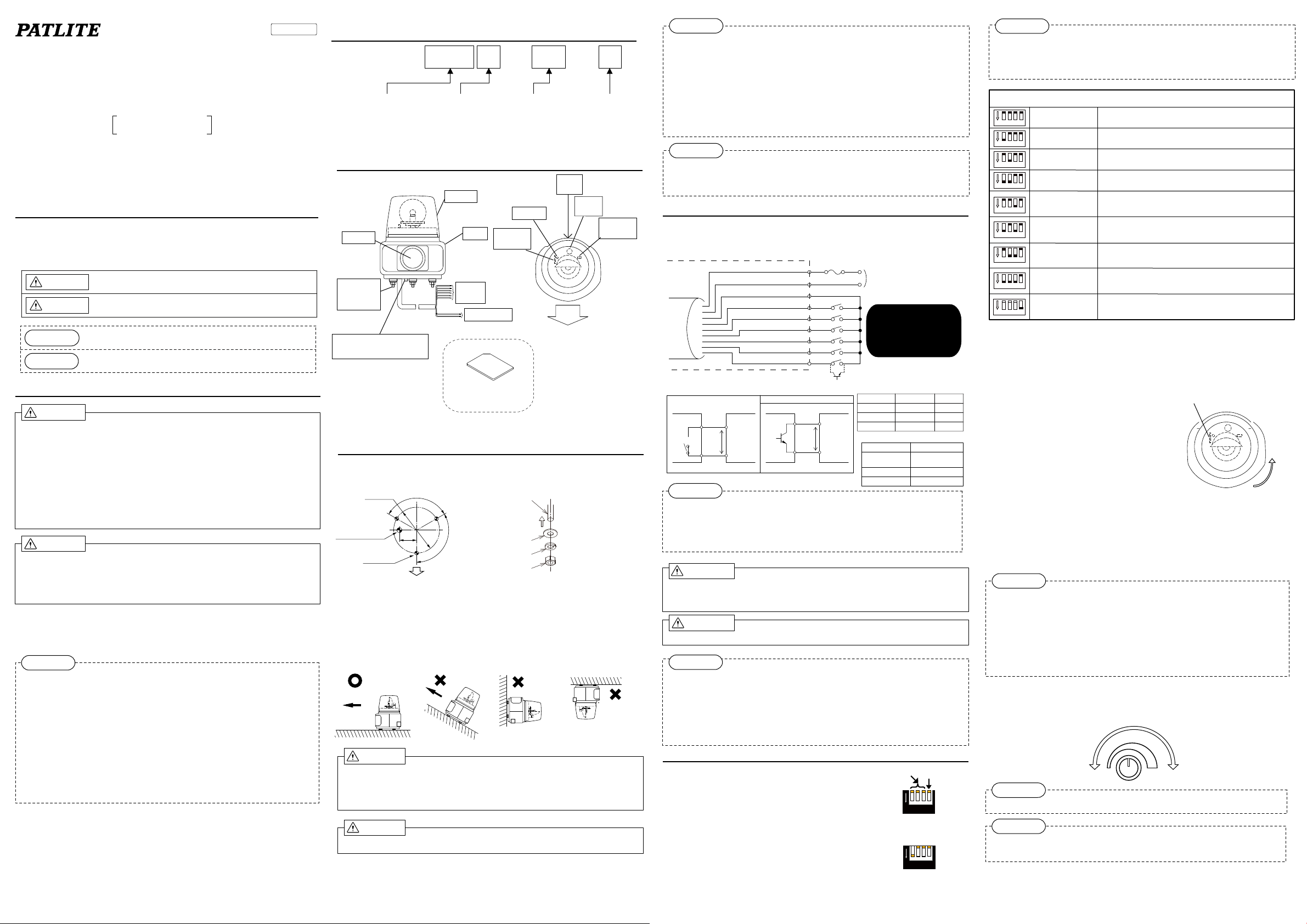
3. Part Names
【Front View】 【Top View】
Globe
Body
Horn
Installation
Feet
3-M8
Signal
Wires
SD Card
Slot
Power Cord
Earth Terminal
(See NOTE For AC200V)
(Model:SDV-128P Sold Separate)
Member of the SD Card Association
SD Card
※ Patlite Corporation is a
Volume
Name
Plate
4. Installation
●
Install onto a mounting surface by drilling holes.
(Refer to the Installation Drawing below)
φ140
Cord Hole φ15
Installation
Hole
3-φ9
Installation Drawing (mm)
(View from Installation Surface)
120゜
50
Front Direction
Installation Feet
゜
20
1
Washer
Spring
Washer
Nut
Nut Assembly Drawing
Maximum Installation Thickness: 5mm
Upward
Horizontal
Angle
Position
Upward
Direction
Warning
●
Be sure the power is disconnected before wiring or installing this product. Possibility of
electric shock may occur.
● Request the installation and wiring be accompanied by a professional contractor. Possiblility
of fire, electric shock or falling from high places may result.
Caution
● Ensure the installation surface is sufficient enough to handle the weight of the product.
Globe Color
RY:Red
G :Green
B :Blue
※ Serial Number is
Printed here.
Spare
Bulb
Selection
Switch
Front
Direction
Remove the Washer,
Spring Washer and Nut
before intallation and
use when mounting.
Recommended Torque
is 6.2N・m.
:Yellow
Inverted
PLEASE
● When installing in high places, choose a location which is accessable by a scaffold, ladder,
etc., for repairs.
● When opeating the product by controlling the power ON/OFF, be sure to include a switch by
which the power supply can be easily cut near the main power for safety.
● Do not attach with the speaker horn in an upward angle. Water and dust can enter and cause
failure.
● Do not install the product in an inverted or upright position.
● Do not pull the wires while wiring, or push it into the main body.
● Perform a periodic maintenance check, tightening screws, bolts, etc., to prevent the product
from falling if installed in a place where vibration occurs.
NOTE
● Depending on the material quality and thickness of installation surface and volume, the
product may resonate and cause an oscillating sound.
● The lifespan of the bulb will be shortened if installed in a location of intense vibrations.
5. Wiring
When wiring to external contacts, use non-voltage contacts such as relays or switches, or open
collector circuits (NPN). Refer to the following circuit diagrams for circuit wiring configurations.
External Fuse
Power (White)
Power (Black)
Signal Common (Brown)
Signal Rotation (Red)
Signal CH1 (Lt. Blue)
Signal CH2 (Yellow)
Signal CH3 (Peach)
Signal CH4 (Lt. Green)
STOP (Blue)
Table1. Signal Wire Circuit Diagram
Non-voltage Contact Circuit
External
Contact
※Voltage drop at DC24V ※Voltage drop at DC24V
RT
6mA
Each
←
Signal
Wire
18V
※
Common Common
NPN Open Collector Circuit
External
Contact
6mA
←
18V
※
Refer to Table 2
External Contact
(Table3)
RT
Each
Signal
Wire
Power Supply
(For DC24V, Black is negative)
Power Cord (0.75mm2)
Signal Wire (0.3mm
Do not apply voltage
directly to the signal
wires, possible
damage may occur.
←Wire for NPN as indicated
in the figure on the left.
Table 2. Inrush Current/Fuse ※1
Model Inrush Current Fuse
RT-24VF/24VFUL
Voltage Capacity
Leakage Current
ON Voltage(V
Max. 10A /20ms
RT-100VF
RT-200VF
Table 3. Signal Wire Contact Capacity
Withstanding
Voltage
Nominal
Nominal
No more than 10mA
No more than DC27V
No more than 0.1mA
)
1V or less
sat
2
)
250V 2A
250V 0.5A
250V 0.5A
NOTE
※ For AC200V
Remove the M4 grounding terminal screw at the bottom of the product. Crimp an “O” terminal
connector to the ground wire. Reconnect the ground terminal to its original position after checking the
crimp connection. The recommended gauge for the earth wire is AWG 16. For wire gauge larger than
AWG 16, please purchase additional connectors etc. It is recommended to use a crimping tool that
corresponds to the crimp terminal being used.
Warning
● Ensure the power has been disconnected. Possible electric shock may occur.
● Ensure the wiring is corrrect before connecting the power. Miswiring may result in failure or
product damage.
Caution
● To protect the power supply and other internal circuitry, be sure to connect an external fuse.
PLEASE
● Check for proper wiring before switching on the power supply.
● To take countermeasure steps against noise, shorten the wiring as much as possible, and it
is recommended to use shielded wire. Moreover, if a high-voltage line is in close proximity
to the wiring where it is easy to intercept noise, it may influence signal inputs and possibility
cause product malfunction.
● When you control two or more products simultaneously, use independent contacts.
*1 When using non-voltage contacts, such as relays, include the inrush current value. If the
capacity is not enough, it will cause arcing, pitting or other malfunctions to the contacts.
6. How to Operate
6-1. Playback Mode Selection
Nine Modes are possible with the selection switch.
6-1-1 Playback Mode Selection Procedure
● Select the switch according to the desired mode.
● Re-insert the power supply.
● Verify the selected playback mode by playing each channel.
Playback Mode
Selection Switch
(Factory Setting:
4 or less recorded messages)
Selection Switch
(Factory Setting:
5 or more recorded messages)
1 2 3 4
ON
1 2 34
ON
Test Mode
4
PLEASE
● Use tweezers, small flat-head driver, etc., to change the selection switch.
● Do not force the selection switch when changing it. The selection switch is delecate and
easily breakable.
● Do not short-circuit the signal wire to ground in the TEST mode.
Playback Mode (Operation Mode Switch Settings)
Bit Input
1 2 3
ON
4
1 2 3
ON
4
1 2 3
ON
4
1 2 3
ON
4
1 2 3
ON
4
1 2 3
ON
4
1 2 3
ON
4
1 2 3
ON
4
1 2 3
ON
4
Refer to [6-5. Message Playback Method] for a detailed explanation of operation.
Mode
Binary Input
Mode
Bit Input Sound
Reduction Mode
Binary Input Sound
Reduction Mode
Bit Input Interrupt
Playback Mode
Binary Input Interrupt
Playback Mode
Bit Input Hold
Playback Mode
Binary Input Hold
Playback Mode
Test Mode
A maximum of 4 messages can be used from CH1 toCH4
A maximum of 15 messages can be used from CH1 toCH4
A maximum of 3 messages can be used from CH1 toCH3.
When an input is applied to CH4, the volume decrease by 20dB.
A maximum of 7 messages can be used from CH1 toCH3.
When an input is applied to CH4, the volume decrease by 20dB.
A maximum of 4 messages can be used from CH1 toCH4.
If an input is applied while a message is in playback, the mesage
playing will stop and resume after the interrupted message ends.
A maximum of 15 messages can be used from CH1 toCH4.
If an input is applied while a message is in playback, the mesage
playing will stop and resume after the interrupted message ends.
A maximum of 4 messages can be used from CH1 toCH4.
While the input is held on, the message will playback. When the
input is released, the mesage playback will stop.
A maximum of 15 messages can be used from CH1 toCH4.
While the input is held on, the message will playback. When the
input is released, the mesage playback will stop.
Message number 1 will playback (selection switches1 to 3 will
have no effect). To end the test mode, set switch 4 back to the
“OFF” position.
6-2. Recording Message
By using our PATLITE Playlist Editor (download from our homepage is possible without
extra charge), an SD card (Model: SDV-128P sold separately), and an MP3 sound
editing tool, the message can be rewritten. The maximum playback time for this product
is 63 seconds (at a rate of 64kbit/s, Fs=44.1kHz and internal memory size of 504Kb).
Refer to the “Help” section of the corresponding software for the procedure to create the
MP3 Data and storing it onto an SD Card.
SD Card Slot
6-2-1 Message Registration Procedure
●
Turn the globe counterclockwise to remove it.
●
Turn the product on.
●
Insert the SD card containing the stored messages
into the slot, and a beeping sound will indicate the data
is being registered.
* C
autionary Note: The message registration cannot be
performed during playback. Even if the power is
turned on after the SD card has been inserted, the message
registration will start.
●
Once the data registration is complete, the product will indicate
completion with a short beep and the SD card can be extracted.
* Rewriting should be completed within 60 seconds. If an indication of long beeps are
sounded, or no indication whatsoever occurs, it is an indication of an error while registering
the data. Refer to "[8. Before Requesting Repair]" for troubleshooting. Also, verify the
volume is not at a minimum level when the beeping sounds cannot be heard.
●
Playback the messages for each channel to check that the rewriting was done properly.
Front
View
Globe
Removal
Direction
PLEASE
●
Optional SDV-128P type should be used for the SD card. Using other SD cards is not
guaranteed for proper operation.
●
When formatting an SD card, please use the FAT16 format.
●
To prevent the possibility of damage to the product or SD card, please beware of the
following.
・
When inserting the SD card in the card slot, be careful of the direction of the SD card.
・
Do not forcibly insert the SD card into the card slot.
・
Do not operate the product with the SD card inserted.
・
Avoid any foreign substances from entering the card slot.
6-3. Volume Adjustment
The sound level is adjustable by the volume control.
● Remove the globe by turning counterclockwise. (Refer to 「6-2. Recording Message」)
● Turning the built-in volume clockwise will increase the volume.
Minimum
Volume
VOL
Maximum
Volume
MAX
PLEASE
● Turn the volume lightly, a torque over 0.3N・m can damage the volume control.
NOTE
● As the sound increases, the possibiliy of distortion may also occur.
● Due to environmental conditions and tolerances. the volume may not be at zero sound
level.
6-4. Rotating Light Operation
Short the rotating light wire to common for the rotating light to operate.
6-5. Message Playback
Turn the product on and when the signal line to common is short-circuited, a message will playback.
・Short the signal wire to common for 100ms or more (pulse input) to play back a message once.
・When controlling this product via the power supply, start-up time is at least 0.5 seconds.
・The STOP input and CH input timing for message playback is common to all modes. Please
refer to the following table for operation.
・When two or more signal wires are simultaneously short-circuited to the common line for bit
input, the larger number of the channels is played back.
Input priority: STOP>CH4>CH3>CH2>CH1
Input Timing (Bit)
Input Hold
CH
100ms or more
Input
Voice
Playback
Other channel inputs are not received
untill the played back message
finishes. (Priority input mode and test
mode are the exception)
100ms
Playback lag
about 300ms
Stablized
Input
Input Timing (Binary)
Input Hold
CH
100ms or more
Input 2
Input Hold
CH
100ms or more
Input 1
Playback lag
Voice
Playback
Input a binary channel within 5 ms, and
hold it for 100 ms or more. Binary channel
inputs are not received untill the end of the
played back message. (Priority input mode
and test mode are the exception)
about 300ms
Input Timing (STOP)
Input Delay
STOP
100ms or more
Input
Voice
Playback
A STOP input is received at any
time. (Test Mode is an exception)
100ms
STOP lag time
about 300ms
Stablized
Input
NOTE
● Although a pop noise may occur when the playback is controlled via the power supply or
playback start and finish, it is not an indication of failure.
● Even when starting two or more units simultaneously, a lag will occur during message
playback.
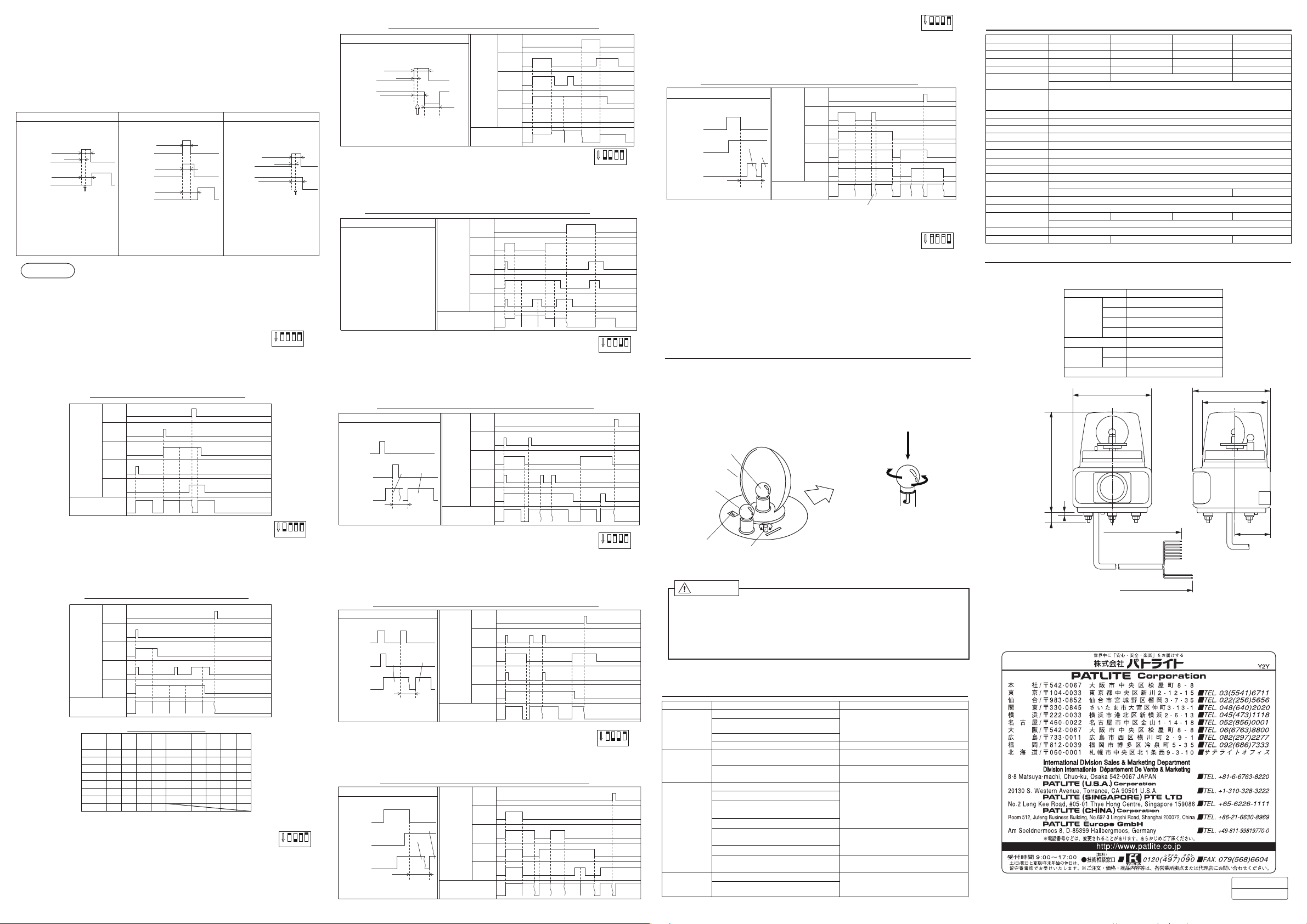
6-5-1. Bit Input Mode
If the signal wires from CH1 to 4 are short-circuited to common, the message of the selected
channel will play back.
● Any input other than STOP will not be received during message playback.
Signal Input Timing Chart (Bit Input)
STOP
CH4
Signal
CH3
Input
CH2
CH1
Message No.
No.2 No.4 No.3 No.3
6-5-2. Binary Input Mode
If the signal wires from CH1 to 4 are short-circuited to common, the message corresponding to
the binary input conversion table will be played back. (Refer to the binary input conversion
table)
● Any input other than STOP will not be received during message playback.
Signal Input Timing Chart (Binary Input)
STOP
CH4
Signal
CH3
Input
CH2
CH1
Message No.
No.15 No.5 No.1 No.1 No.3
Binary Input Table
Message
CH1 CH2 CH3 CH4
No.
1 1 0 0 0
2 0 1 0 0
3 1 1 0 0
4 0 0 1 0
5 1 0 1 0
6 0 1 1 0
7 1 1 1 0
8 0 0 0 1
※ A”1” in the table refers to the short-circuit of the signal line to the common line.
6-5-3. Bit Input Sound Reduction Mode
Channel 1 to 3 corresponds to a bit input.
Channel 4 corresponds to a 20dB sound reduction of the message.
● Channel 4 is not a priority in this mode.
● Any input other than STOP or sound reduction will not be received during message playback.
(Selection Switch
(Selection Switch
Message
CH1 CH2 CH3 CH4
No.
9 1 000 1
10 0 1 0 1
11 1 1 0 1
12
0
13
1
14
15
0
0
1
1
1
(Selection Switch
:
1 2 3
ON
4
:
)
1 2 3
ON
4
1
1
1
1
1
1
1
1
:
)
1 2 3
ON
Signal Input Timing Chart (Bit Input Sound Reduction)
Input Timing
Input Hold Time
100ms or more
CH4 Input
(Red.)
Sound
Volume
100ms
Full Vol. Full Vol.
Stablized
Input
Red.
Reduction
Return
lag time
ab. 300ms
Reduction lag
time
ab. 300ms
6-5-4. Binary Input Sound Reduction Mode
STOP
CH4
(Red.)
CH3
Signal
Input
CH2
CH1
Message No.
Red.
No.3
(Selection Switch
Channel 1 to 3 corresponds to a binary input.
Channel 4 corresponds to a 20dB sound reduction of the message.
● Any input other than STOP or sound reduction will not be received during message playback.
Signal Input Timing Chart (Binary Input・Sound Reduction)
Input Timing
Same as Bit Input・Sound
Reduction Mode. See [6-5-3
Bit Input・Sound Reduction
Mode].
Signal
Input
STOP
CH4
(Red.)
CH3
CH2
CH1
Red.
Red.
No.2
No.2
No.3
(Selection Switch
)
6-5-5. Bit Input Interrupt Playback Mode
Message No.
Red.
No.7
When the signal wires from channels 1 to 4 for a bit input are entered and the next input is during
message playback, the message under playback is interrupted for the next message to playback,
and resumes after the next message ends.
● Even if the input is held on, the message playback is only reproduced once.
Signal Input Timing Chart (Bit Input Interrupt Playback)
Input Timing
CH2
Input
CH1
Input
No.2 No.1
Voice
Playback
within 300ms
6-5-6. Binary Input Interrupt Playback Mode
STOP
CH4
Signal
CH3
Input
CH2
CH1
Message No.
No.4 No.4 No.2 No.2 No.3 No.1
(Selection Switch
No.2
:
ON
:
:
Red.
No.6
ON
ON
Red.
No.2
1 2 3
1 2 3
1 2 3
6-5-8. Binary Input Hold Playback Mode
(Selection Switch
:
ON
If the signal wires from CH1 to 4 are held down to common, a message is played while
holding.
Playback will stop when an input is lost.
Signal Input Timing Chart (Binary Input・Hold Playback)
Input Timing
CH2
Input
CH1
)
4
Input
Voice
Playback
within 300ms
No.3
No.1
6-5-9. Test Playback Mode
STOP
CH4
Signal
CH3
Input
CH2
CH1
Message No.
No.15 No.2No.7
No.15
(Selection Switch
No.7 No.3 No.1
:
)
ON
Message from CH1 continues being played back. Any other CH inputs are
ignored during test playback.
・ Use the “Test Playback Mode” when checking the operation or adjusting the
volume.
・ To operate in the “Test Playback Mode”, select the “Operation Mode Switch” to
any mode from “I” to “P”.
・ Because the “Test Playback Mode” automatically resets the “Operation Mode” to
‘A’, reboot the product after exiting the “Test Playback Mode” in order for the new
settings to take effect.
)
4
7. Bulb Replacement
When the bulb is burned out, use the following steps to replace it with the spare bulb.
● Turn power “OFF”.
● Remove the Globe. (Refer to [6-2. Recording Message])
● Push the bulb down and turn counterclockwise to remove it.
● Push the new bulb down and turn clockwise to install it.
● Place the globe back on, ensuring it is sealed tight.
Push Downward
Bulb
Mirror
Spare
Bulb
)
4
Selector
Switch
Volume
Front Direction
Clockwise
(Install)
1 2 3
4
1 2 3
4
Counterclockwise
(Remove)
)
9. Specifications
Model Name
Rated Voltage
Operating Voltage Range
Consumption Current
Rotating Speed
Bulb Type
Sound Pressure Level
Sound Reduction Function
Audio File
File Format
Internal Memory Size
Signal Input Method
Start-up Delay
Number of Playback Messages
Operating Temperature Range
Relative Humidity
Mounting Location
Protection Rating
Insulation Resistance
Withstanding Voltage
Vibration Resistance
Mass
Maximum Volume 105dB : Placed on a 300mm
wave at a -6dB input.
Volume Adjustable.※Sound level of message will vary with the surrounding environment.
MPEG1 - Audio Layer III (MP3) Standard Bit Rate : 64kbits/s, Sample Frequency (Fs)=44.1kHz
AC 500V for 1 minute AC 500V for 1 minute
RT-24VF RT-24VFUL
DC 24V AC 100V (50/60Hz) AC 200V (50/60Hz)
DC 21 - 27V AC 90 - 110V AC 180 - 240V
24W± 25%
115± 30rpm 105± 30rpm
24V 20W
-20dB
±2dB
504kB (Total MP3 Data)/Maximum Playback time: 63 sec (at standard bit rate of 64kb/s)
No less than 300ms (no less than 500ms when Power is controled)
1M
Ω or more (at
19.6m/s
RT-100VF
32W± 20% 30W± 20%
Glass Bulb : G18 Base BA15S
drop at maximum volume with a 1kHz sine wave signal input at -6dB.
Bit/Binary Input (Dependent Upon Selection Switch Input)
Bit Input : 4 / Binary Input : 15
-10℃ to +50
No more than 85% RH (No Condensation)
Indoor and Outdoor Use
DC 500V) between conductive and non-conductive metal parts.
AC 1000V for 1 minute
Between conductive and non-conductive metal parts.
2
(30Hz Back and Forth: 2h・Right to Left: 2h・Up and Down:4h)
Upright Postion Only
RT-200VF
95± 30rpm
2
base at a distance of 1 meter with a 1kHz sine
FAT16
℃
IP 23
AC 1500V for 1 minute
2.4kg± 5%2.0kg± 5% 2.0kg± 5%
10. Maintenance Parts
● Refer to the address and phone numbers below to contact your PATLITE Sales
Representative for maintenance parts.
【Outer Appearance】
260
23
※Earth Terminal
(For AC200V)
Part Name Part Number
Red
Yellow
Globe
Green
Globe Packing
Bulb
Blue
12V 15W
24V 20W
Rotor Rubber
200
6
※
Length from
Cord Hole:ab.300
A31110018-1
A31110018-2
A31110018-3
A31110018-4
C33410001
D01201503
D02402003
A51120003
198
φ162
DC 24V
DC 21 - 27V
24W± 25%
115± 30rpm
24V 20W12V 15W
Indoor Use Only
※
88
When the signal wires from channels 1 to 4 for a binary input are entered and the next input is
during message playback, the message under playback is interrupted for the next message to
playback, and resumes after the next message ends.
● Even if the input is held on, the message playback is only reproduced once.
Signal Input Timing Chart (Binary Input Interrupt Playback)
Input Timing
CH 2
Input
CH 1
Input
No.3
No.2
Voice
Playback
within 300ms
6-5-7. Bit Input Hold Playback Mode
If the signal wires from CH1 to 4 are held down to common, a message is played while holding.
Playback will be stopped if an input is lost.
STOP
CH4
Signal
CH3
Input
CH2
CH1
Message No.
No.15 No.9 No.11 No.5
(Selection Switch
:
)
1 2 3
ON
4
Signal Input Timing Chart (Bit Input Hold Playback)
Input Timing
CH 2
Input
4
CH 1
Input
No.1
No.2
Voice
Playback
within 300ms
STOP
CH4
Signal
CH3
Input
CH2
CH1
Message No.
No.4 No.3 No.2 No.2 No.2No.3 No.1 No.1
Caution
● Before changing the bulb, be sure to disconnect the power. Possible short circuiting may
occur.
● Remove the bulb after it has plenty of time to cool down. Handling while hot may inflict
burns.
● Do not use bulbs other than what is specified in [9. Specifications] or what is indicated on
the Name Plate located on the product. Possible damage, failure or fire may occur.
8. Before Requesting Repair
Problem
No
Sound
Different
Channel
Plays Back
Cannot
Record
Message
Rotating Light
’
t Work
Doesn
Is there power supplied?
Is the signal line to common line short-
circuited correctly?
Is the STOP input on?
Is the volume turned down to minimum?
Is the signal line to common line short-
circuited correctly?
Is the selection mode switch set correctly?
Is there power supplied?
Is the playlist created on the SD card?
Is the file name and contents of the playlist
folder right?
Is the data storage location correct?
Is the SD card an option product from our
company?
Is the SD card inserted correctly?
Is the selection switch position 4 set to ON
(test reproduction mode) during playback?
Is there power supplied?
Is the signal line to common line short
circuited correctly?
Where to Check
What to do
Double check the wiring. (5. Wiring)
Adjust the volume. (6-3. Volume Control)
Double check the wiring. (5. Wiring)
Double check the Selection Switch.
(6-1. Playback Mode Selection)
Double check the wiring. (5. Wiring)
Double check the contents of the SD Card
Playlist and Data Folder. (FV-Win or
Patlite Playlist Editor Help File.)
Double check the SD Card.
(6-2. Recording Message)
Double check the Selection Switch.
(6-1. Playback Mode Selection)
Double check the wiring. (5. Wiring)
※ Specifications may change without notice due to continual product improvement.
● Despite the cautions and warnings provided in this manual, it is not the responsibility of
PATLITE for any failure or damage occured from mishandling.
● Due to changes,improvements,etc., contents of this manual may change without advance
notice.
Length from
Cord Hole: ab.320
Unit:(mm)
4264-A
'10.10 .NHI
 Loading...