


PATLITE FV-127JP User Manual
V95100117
MP3 File Playback Circuit Board
User’s Manual
[ TYPE FV-127JP ]

Index
Introduction 3
1. Product Summary 3
2. Safety Precautions 4
3. Part Names and Function 5
4. Installation 7
5. Wiring 8
5-1. Terminal Wiring and Names 8
5-2. Wiring 9
5-2-1 Power Input Terminal Wiring 10
5-2-2 FG Terminal Wiring / Noise Reduction Pin 11
5-2-3 Speaker Output Terminal Wiring 12
5-2-4 AUX Output Terminal Wiring 13
5-2-5 BUSY Output Terminal Wiring 14
5-2-6 Input Terminal Wiring 15
6. Volume Adjustment 16
6-1. Volume Adjustment 16
6-2. Reduction Function 16
7. Mode Switch Settings 17
7-1. Channel (CH) Terminal Input 17
7-2. Playback Modes 19
7-3. SD Card Operation 25
7-4. Input Hold Time 29
7-5. Speaker Output 29
8. Playback Method 30
9. Error Table 31
10. Binary Input Table 32
11. Optional Sales Items 33
12. Before Requesting Service 34
13. Specifi cations 35
14. Guarantee Provisions 37
Concerning the Product Guarantee 37
Duration of Guarantee 37
Concerning the Warranty Contents 37
Items Outside Warranty Limitations 37
Guarantee Disclaimer 37
Limitation of Liability 37
- 2 -

Introduction
Thank you for purchasing our Patlite Signal Voice MP3 Playback Circuit Board. Prior to installation, please read
through this manual for proper installation and precautionary steps. In additon, please store this manual for future
reference when performing maintenance, repairs or inspections.
After reviewing this manual, if there are any inquiries, please direct them to your PATLITE Sales Representative.
• Markings in this book
The bit rate of 64 kbit/s is given as the standard rate for the MP3 fi le. When the bit rates differ, reproduction time differs.
Optional SDV-128P should be used for the SD card. Using other SD cards is not guaranteed.
(☞ Refer to page 38 [(1) SD card (MP3 voice messages")]
Format the SD card using the FAT16 protocol. The SD card cannot be recognized if it is formatted in any form other than
FAT16.
• Copyrights
Work that was recorded or copied from music CDs or other media used in public places may infringe upon copyrights
and law enforcement may be imposed. When using a work that was recorded or copied from music CDs or other media,
be sure to obtain permission from the author.
Moreover, the copyright of the sound and music data which PATLITE Corporation distributes or sells belongs to our
company. In addition, copyrights of audio/music data distributed or sold by PATLITE Corporation belongs to PATLITE. It
is strictly prohibited to copy/reprint whole or partial contents of audio/music data belonging to PATLITE Corporation, or to
transfer/sell such material on computer networks etc. without the permission of the rightful holder.
● Windows® is a registered trademark of Microsoft Corporation of America, Japan and other countries.
● The PATLITE Corporaation is a member of the SD Card Association.
1. Product Summary
This product is a small sized MP3 fi le reproduction board which can also be used for factory automation (FA).
Since MP3 is used as compressed data, it is possible to reproduce a high-quality sound voice message for an
extended period of time. Moreover, the registered voice message can be rewritten freely. (A maximum of 127
messages can be registered)
• High Quality Sound/Long Playback Time
The maximum voice message playback is a maximum of about 8 minutes.
Moreover, extende reproduction for a maximum of about 240 minutes can be done by using the optional SD card.
• Voice Message Rewrite - Export Function
A voice message can be rewritten freely using the SD card.
The voice messages registered to this product can be read to the SD card.
• Noise Reduction
Malfunction due to noise can be suppressed by the setup of input noise fi lters.
The noise reduction pin can reduce the effect of noise according to the environment.
• Replay According to Application
Five different modes can be selected for different playback modes.
With the control of an external signal, three levels of noise reduction can be made.
- 3 -
2. Safety Precautions
In order to prevent any damage to the user and other personnel or to assets, note the following:
The warning indications are divided into the following classes according to the degree of danger or damage incurred when the
warning is not taken into consideration and the product is not correctly used.
9CTPKPI
%CWVKQP
For safe application, observe the following:
Indicates an immediately dangerous condition: failure to follow the instructions may lead to
death or serious injury.
Indicates a potentially dangerous condition: failure to follow the instructions may lead from
slight to medium injury or to property or physical damage.
9CTPKPI
• Ensure the power is in the correct tolerance for voltage supply. Failure to do so may result in malfunction or fi re.
• Do not modify or disassemble the product. Failure to do so may result in malfunction or fi re.
• During operation, the parts get hot, so do not touch the product and keep fl ammable things away. Failure to do
so may result in serious burns or fi re.
%CWVKQP
• Before handling this product, be sure to discharge any static electricity by touching other metal parts to discharge
static electricity. Moreover, don't touch the parts or printed circuit board pattern that is not specifi ed.
• The parts on a board may be destroyed by static electricity, or the part leads may cause injury. This product
incorporates a circuit board for exclusive use. Protect the board from conductive foreign substances, such as
water and dust.
• Don't allow tools etc. to contact with the board. The possibility of short-circuiting and part damage may occur.
• Make sure the power is off before wiring and mounting. The danger of burning the internal circuitry by shortcircuiting may occur.
• Don't install the product in a location where vibrations exceed the specifi cations. Possible product damage or
falling may occur.
• This product is not guaranteed from failure produced by transportation, handling, natural disasters, etc. or the
disassembly and modifi cation contrary to warnings and notes. Moreover, please avoid the use of this product
outside the contents written in this book.
Please
• For safety purposes, be sure to carry out daily inspections and to perform preventative maintenance which can
avoid down-time and possible failure.
• Don't control message reproduction by controlling the power source. Possible malfunction may occur.
• Don't use in a location with corrosive gas present. Possible malfunction may occur.
• Use this product only in environmental conditions indicated in this manual. Possible malfunction may occur in
another environment.
- 4 -
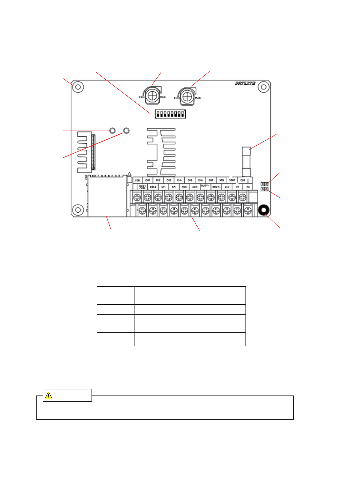
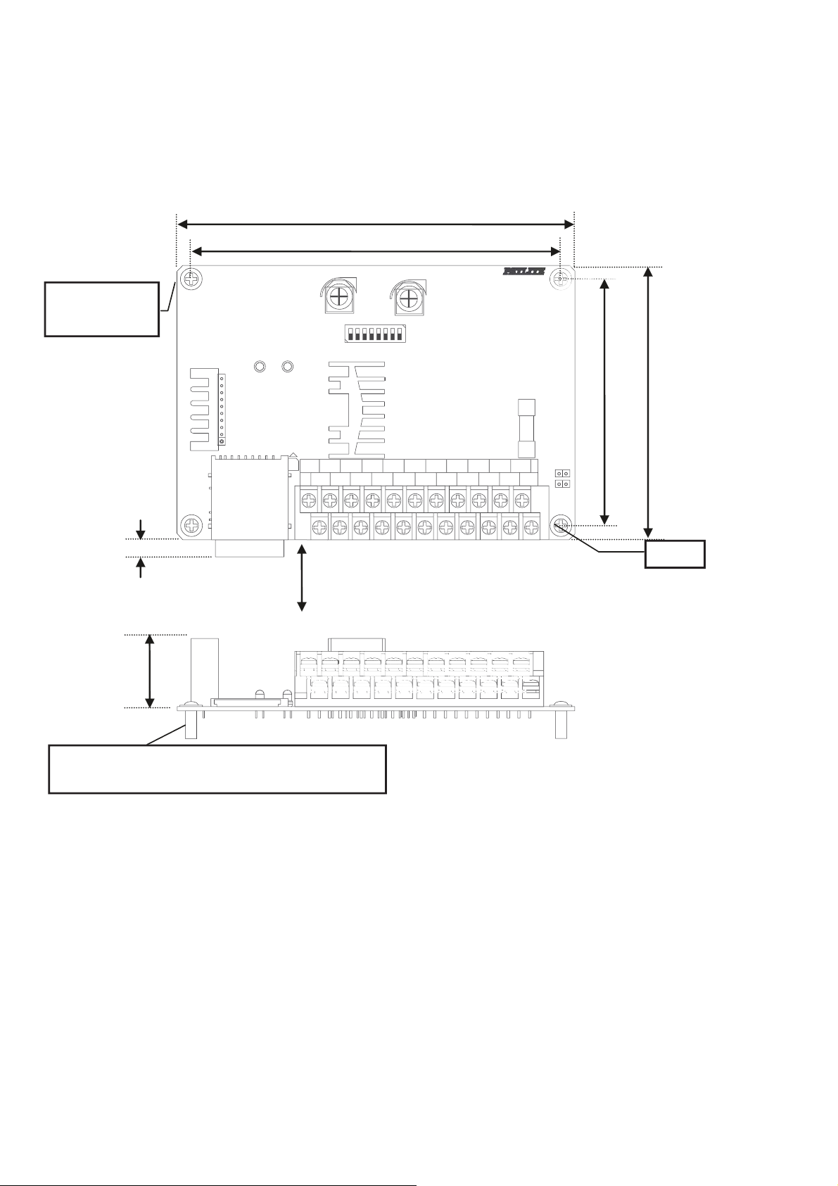
3. Part Names and Function
1) Installation
Holes 4-φ3.5
2) Power Indicator
LED (Green)
3) Status Indicator
LED (Red)
7) DIPSwitches
8) Installation
Holes
5) Volume Volume
(AUX) Speaker)
6) Terminal
Block
4) Glass
Fuse
10) Noise Filter
Pin B
Noise Filter
Pin A
9) FG
Hole
1. Installation Holes 4-φ3.5
Use the installation holes when mounting. (☞ Refer to pg. 9 [4. Installation])
2. Power Indicator LED (Green)
The LED light turns on when power is applied.
3. Status Condition Indicator LED (Red)
See the table below for the fl ashing or non-fl ashing indication depending on the function:
LED Status Operation
Off During standby or audio message playback.
On
Flashing
4. Glass Fuse
Fuse to protect from overcurrent or overvoltage. Refer to the specifi cations below when
replacing:
Glass Fuse: φ5.2×20 Rated Current: 1.0A Standard Fusion Type
Replacement Part: Nippon Seisen Co., Ltd. FBM 250V 1A / Fujitsu Electric FGMB 250V
When transferring voice message
When exporting voice message
Error during playback
(☞ Refer to pg. 38 [9. Error Table])
%CWVKQP
Before replacing the fuse, disconnect the power source. The possibility of circuitry shorting or
electrocution may occur.
- 5 -
5. Volume (Speaker, AUX)
Volume adjustment for the Speaker and AUX output is possible.
(☞ Refer to pg. 20 [6-1 Volume Adjustment])
6. Terminal Bus
Wiring terminal for individual Inputs and Outputs. (☞ Refer to pg. 10 [5. Wiring])
7. DIP Switches (Sets Functions)
Sets functions for playback mode, SD card operation, etc.
(☞ Refer to pg. 22 [7. Mode Switch Settings])
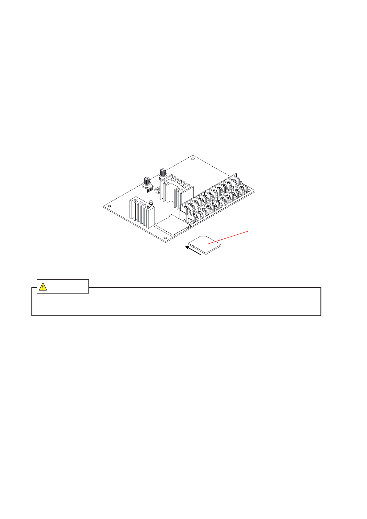
8. SD Card Slot
Used for voice message rewriting, voice message exporting and SD card permanent installation.
(☞Refer to pg. 31 [7-3. SD Card Operation])
[SD Card Slot Insertion]
When inserting, please push the SD Card in until a click is heard, and insert the SD Card as indicated in the
diagram below.
To remove the SD Card, push in until a click is heard and release.
SD
Card
SDCard
Slot
%CWVKQP
When you insert an SD card into the SD card slot, be careful of the direction. Also, don't push in SD card by
force. Possible damage of the product and SD card may occur.
9. FG Hole (Frame Ground Hole)
In some cases, the earth grounding reduces noise.
The Terminal bus is connected to the FG Hole.
10. Noise Filter Pin (A , B)
Depending on the pin setting, incoming noise can be reduced.
Both pins are connected upon shipment, but by removing any of them may increase noise susceptibility.
Therefore, set the pins in accordance to the operating environment.
(☞Refer to pg. 13 [② FG Terminal Wiring/Noise Reduction Pin])
- 6 -
4. Installation
DEC2DEC1
/VOL
CH1
CH2
COMSP-S
CH3
C
U
CH5
CH6BUS
V
CH7
STB0VFGCLR
STO
90100
3
Use M3 screws and PCB spacers (not included) when installing the PC Board.
4-M3
Recommended
Torque: 0.3 N
6 (Insersion Gap)
[mm]
・m
144
1
4
H4
A
P+ AUX-
X+ BUSY-
Ensure enough clearance is made for
the SD Card (W:24mm L:32mm) to be
inserted and removed
P
Y+ 24
FG Hole
Max. 28
Recommended Spacer Size: 10mm
*
(Use metal spacer when grounding via the FG Hole)
For dimensions (☞ Refer to pg. 38 [Outer Dimensions])
- 7 -
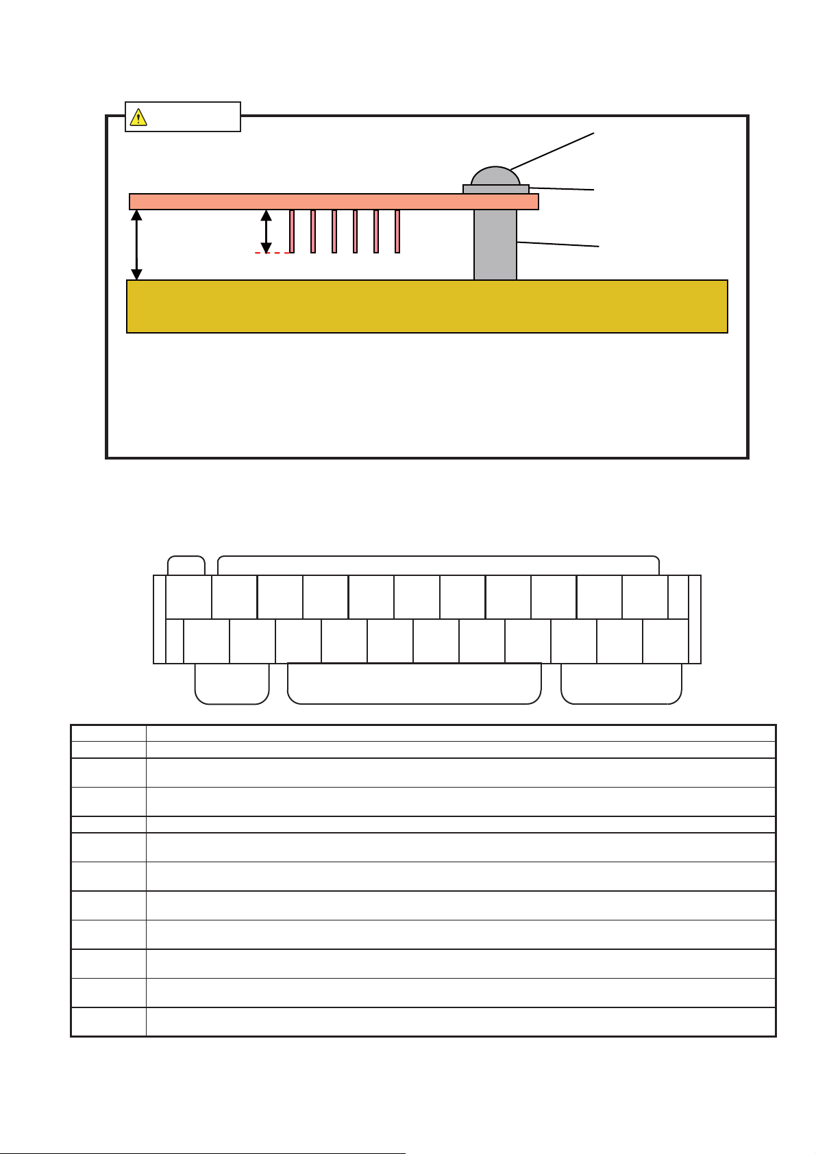
%CWVKQP
• * Ensure the insulation space is suffi cient with a maximum length of 3mm for the lead wires coming
from the PCB. If an insuffi cient space allows the lead wires to touch a conductive surface, a possibility
of short-circuiting may occur.
• Use an 8mm diameter washer. If a washer with a diameter over 8mm is used, contact with the PCB
pattern may cause short-circuiting.
• Use all 4 mounting holes when installing and use the recommended torque to prevent the screws from
loosening and the product from unattaching.
M3 Screw
Washer (φ8mm or less)
Spacer
5. Wiring
5-1. Terminal Wiring and Names
COM
COM CH1 CH2 CH3 CH4 CH5 CH6 CH7 STB CLRSTOP
DEC1
/VOL
Input
Terminal
Name Function
COM Common connection for input terminals
CH1-7
STB
STOP Stops the message during playback.
CLR
DEC1/VOL,
DEC2
SP-,
SP+
AUX-,
AUX+
BUSY-,
BUSY+
24V,0V
FG
Channel selection terminal for audio messages. Short to COM for the selected channel to playback message.
Two input modes "binary" and "bit" can be selected. (☞ Refer to pg. 23 [7-1. Channel (CH) Terminal Input])
When in the Binary Mode, STB is used during playback. (Not applicable for the “Hold Playback” mode)
(☞ Refer to pg. 30 [(E) Hold Playback])
When used during the "memory playback" mode, the audio playback message is erased. For other modes,
the function is the same as the "STOP" mode.
Depending on the input status, the speaker volume or AUX volume decreases.
(☞ Refer to pg. 21 [6-2. Reduction Function])
Speaker Terminal Connection (Note Polarity).
(☞ Refer to pg. 14 [③ Speaker Output Terminal Wiring])
Amplifi er Terminal Connection (Note Polarity).
(☞ Refer to pg. 15 [④ AUX Output Terminal Wiring])
Output is produced during message playback (Note Polarity).
(☞ Refer to pg. 17 [⑤ BUSY Output Terminal Wiring])
Power Input Terminal. Connect DC24V only. (Note Polarity)
(☞ Refer to pg. 12 [① Power Input Terminal Wiring])
When connecting to earth ground (FG), under certain environments can reduce the effect of noise. The FG is
connected internally.
SP- SP+ AUX- AUX+
CH Input Terminals
BUSY- BUSY+
24V 0V FGDEC2
Power TerminalsOutput Terminals
- 8 -
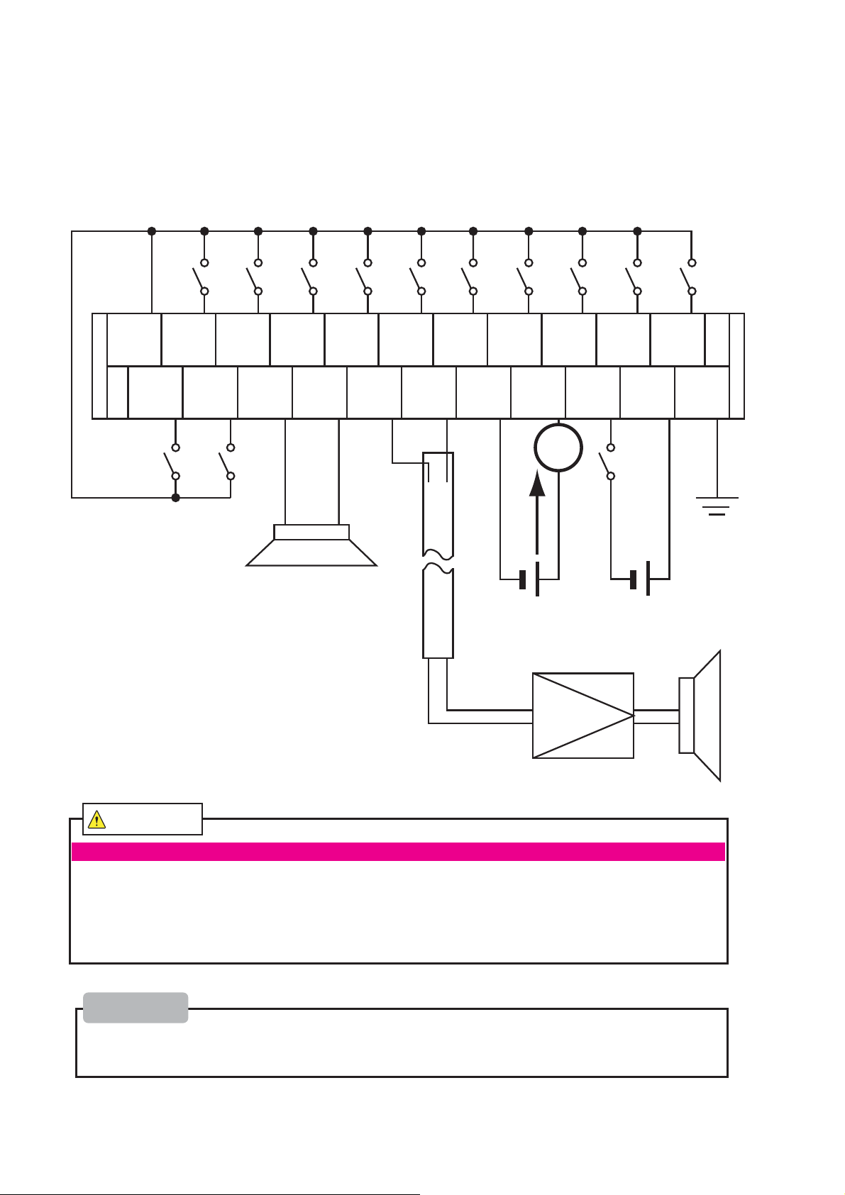
5-2. Wiring
Wiring Example
COM CH1 CH2 CH3 CH4 CH5 CH6 CH7 STB CLRSTOP
DEC1
/VOL
SP- SP+ AUX- AUX+
- +
Speaker
8
Ω
Shielded Cable
BUSY- BUSY+
Max 500mA
- +
Max 40VDC
External
AUX
GND
Amplifier
24V 0V FGDEC2
L
- +
DC24V
+
-
%CWVKQP
Do not connect the input connections to the power supply. Possible malfunction may occur
When handling this product, please do so after discharging static electricity from on the body. Discharge the
static electricity by touching other metal parts. In addition, do not touch parts in areas not specifed in this
manual. Possible static electricity may destroy parts or the wire leads on the underside of the board may
cause injury.
Be sure to turn off the power before connecting wires. Possible short circuiting or burning-out of the internal
circuitry may occur.
Please
Ensure wiring is properly performed before connecting power.
To prevent noise, make wire connections short and use shielded wiring. If installed where high voltage wiring
is nearby, inductive noise may cause malfunctioning.
- 9 -
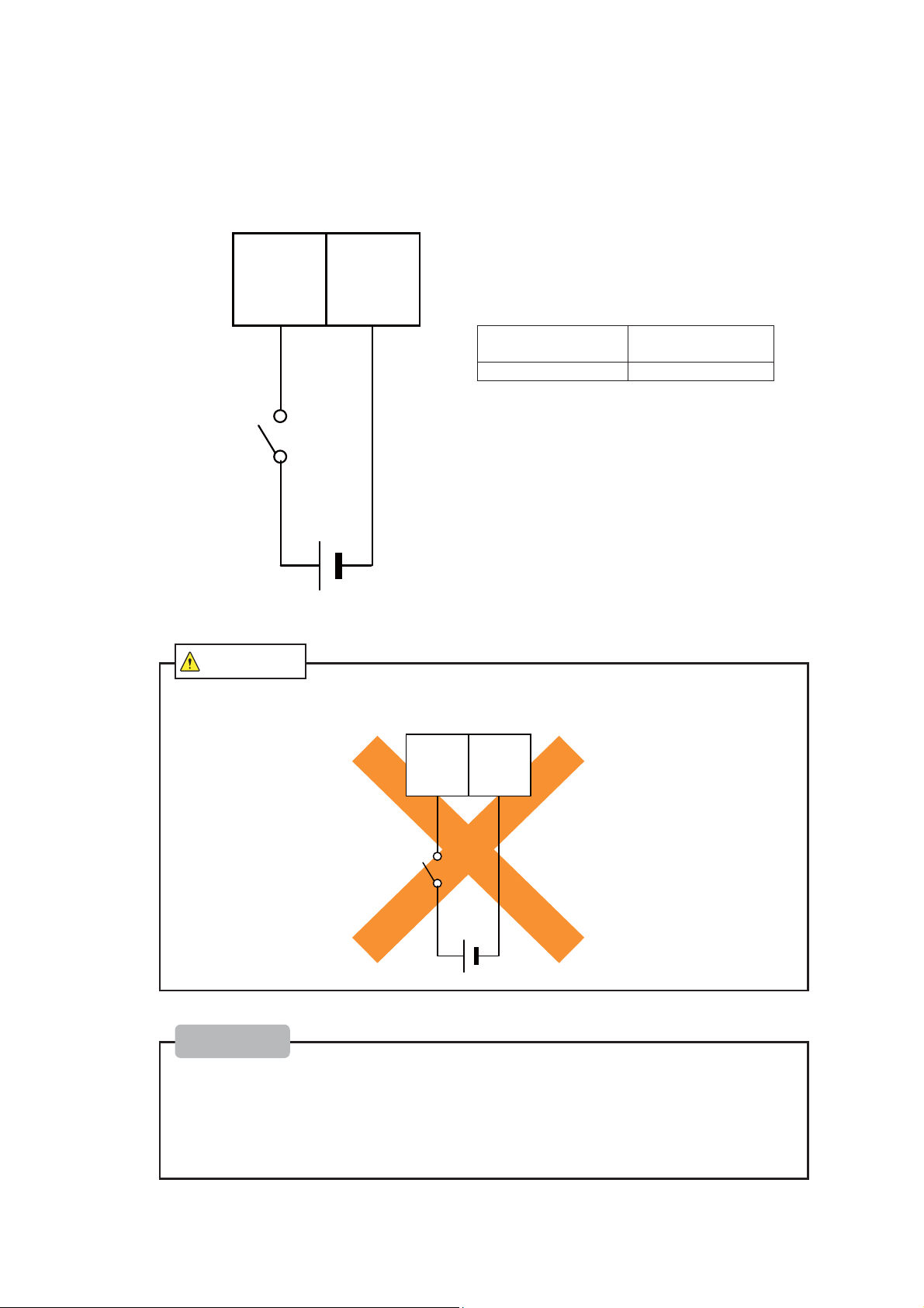
5-2-1 Power Input Terminal Wiring
Connect DC24V.
24V 0V
Current Consumption
Inrush Current 9A
For Maximum Load:
About 520mA
㸩 㸫
%CWVKQP
• Ensure wiring is properly performed before connecting power. If voltage is applied
between 0V and FG, it will cause a short circuit, and the power source will be destroyed.
0V FG
㸩 㸫
Please
• Ensure voltage polarity is correct.
• When used in a state where it is connected to the power source, please include a switch in
which the power source can be easily cut for safety.
• When using non-voltage contacts, such as a relay switch for power source wiring, please
select in consideration of the rush current. If capacity is insuffi cient, it will cause welding of
the contacts and malfunction.
• Use the rated voltage supply when located in a quiet location to avoid white noise.
- 10 -

5-2-2 FG Terminal Wiring / Noise Reduction Pin
When the FG terminal is connected to earth ground, depending on the environment, the noise generated can be
reduced.
The FG hole is connected internally to the circuitry.
FG
Even with the FG Terminal connected to earth ground, in some cases when there is no change in noise reduction,
try changing the pin positions. Depending on the work environment, noise can be reduced by changing the pin
conditions.
Both pins are inserted at time of shipment, but depending on environment, both pins may not be necessary for noise
reduction.
Noise Filter Pin A --- Connects the Analog Ground to FG
Use for Speaker Output / AUX Output Noise Filtering.
Noise Filter Pin B --- Connects the Power Ground and Input Ground to FG.
Use for Input Terminal Line Noise Filtering
Input GND
Analog GND
※
※
One of the two pins are connected upon factory shipment.
The part number for the pin used is JM-2BK-61 [JST Mfg. Co., Ltd.].
FV-127JP
Noise Filter Pin B
Noise Filter Pin A
FG
Terminal
Pull the pin in an upward direction as depicted in the drawing below when removing.
When inserting the pin, ensure it is pushed all the way down as illustrated below.
- 11 -
5-2-3 Speaker Output Terminal Wiring
Connect the speaker. (Note Polarity)
SP- SP+
㧙
㧗
Speaker
8Ω
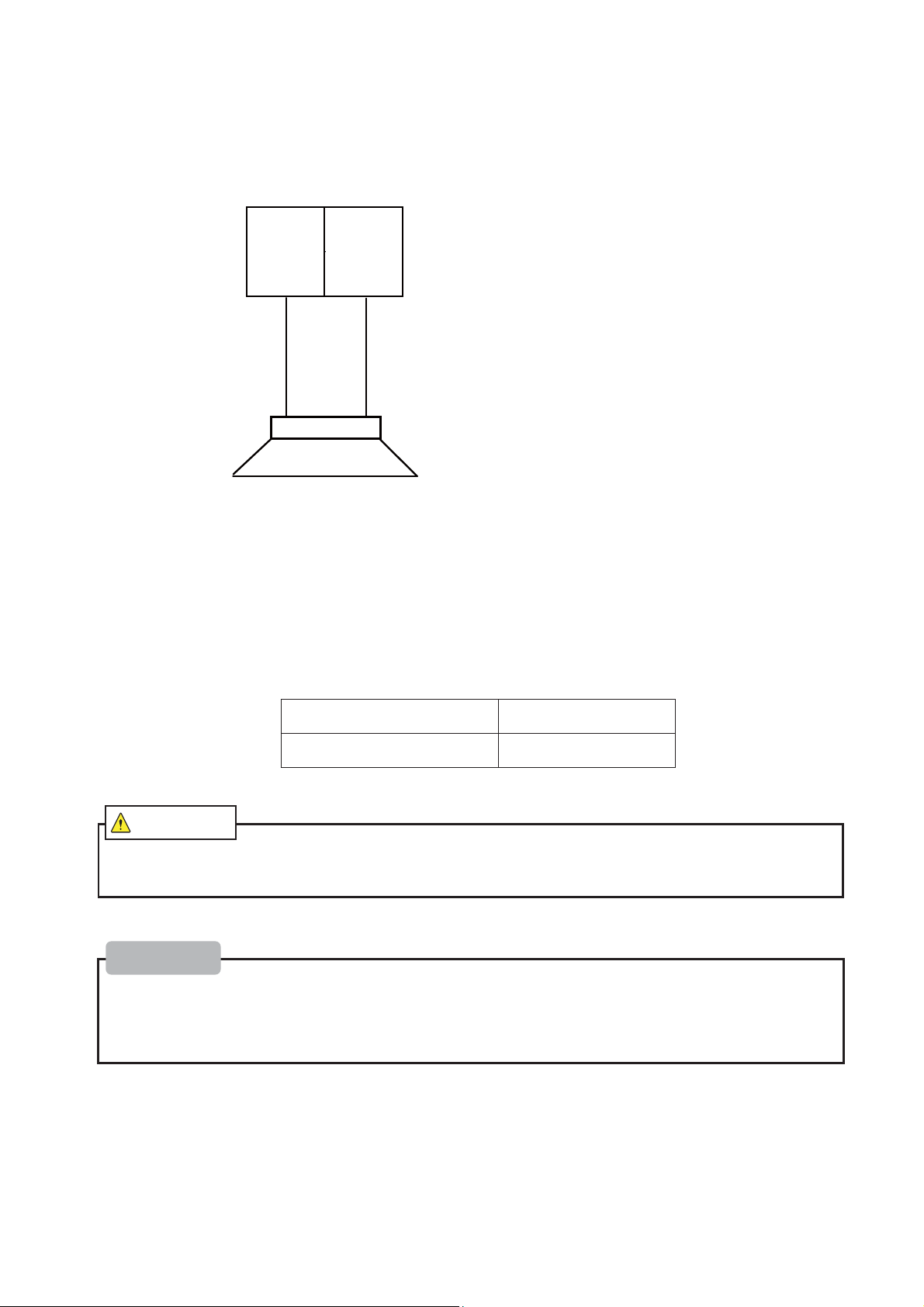
Regarding Compatable Speakers
• The optional SPW-5E (5W) speaker is available (Sold Separately)
(☞ Refer to pg. 38 [④ Horn Type Speaker])
• When installing a speaker for a customer, please follow the guidelines of the following specifi cations.
The speaker output can be changed with the setup for the output.
The speaker output can be changed with a DIP switch.
(☞Refer to pg. 36 [7-5. Speaker Output”])
When the speaker is set for 4W
When the speaker is set for 2W
Speaker Impedance: 8Ω
Rated Input: 4W or more
Speaker Impedance: 8Ω
Rated Input: 2W or more
%CWVKQP
• The speaker ratings should meet the specifi cations. Exeeding the limits may cause product and speaker
damage.
Please
• If the polarity of a speaker is mistaken, volume may drop.
• For the measure against noise, shorten wires as much as possible and use shielded wire. Also, if a highvoltage line is nearby, it is easy to receive an inductive noise, which may cause malfunction, in response to
the infl uence of noise.
- 12 -