

Page 1

Pathport Manager User’s Guide
Suite 103, 1439 - 17 Avenue S.E.
Calgary, AB, T2G 1J9
Canada
Phone: (403) 243-8110
Fax: (403) 287-1281
E-mail: support@pathwayconnect.com
www.pathwayconnect.com
1
Page 2

Pathport Manager User’s Guide
Table of Contents
Table of Contents..................................................................................................2
Installing Pathport Manager..................................................................................3
Setting up your PC................................................................................................9
Starting up your Pathport System.......................................................................14
Running Pathport Manager for the first time:......................................................18
An Introduction to Pathport Manager..................................................................23
Getting Started with Pathport Manager...............................................................25
Advanced Network Setup ...................................................................................27
Pathport Manager's Internal Windows ................................................................29
Creating Universes .............................................................................................36
Building Merges and Backups ............................................................................44
Using Universes..................................................................................................57
Toolbar Commands ............................................................................................58
System Requirements.........................................................................................61
2
Page 3
Pathport Manager User’s Guide
INSTALLING PATHPORT MANAGER
Windows:
From CD
If your computer supports Autorun, simply place the Pathport Manager CD in
your CD-ROM, and the installation procedure should begin. If it does not, double
click on the "pm3inst.exe" file in the root directory of the CD to begin.
From a downloaded file:
Download the pm3inst.exe file.
From Windows Explorer, run the file, starting the installation program.
Once the installation starts, a number of screens will guide you through the
installation process.
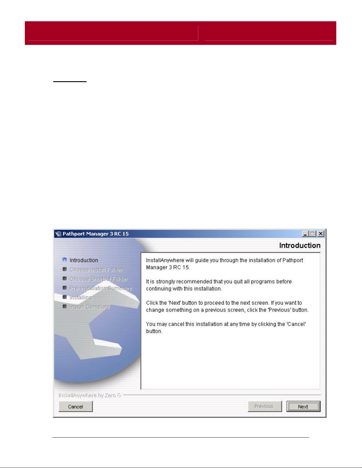
Screen 1:
3
Page 4
Pathport Manager User’s Guide
Pressing "Next" will begin the installation process.
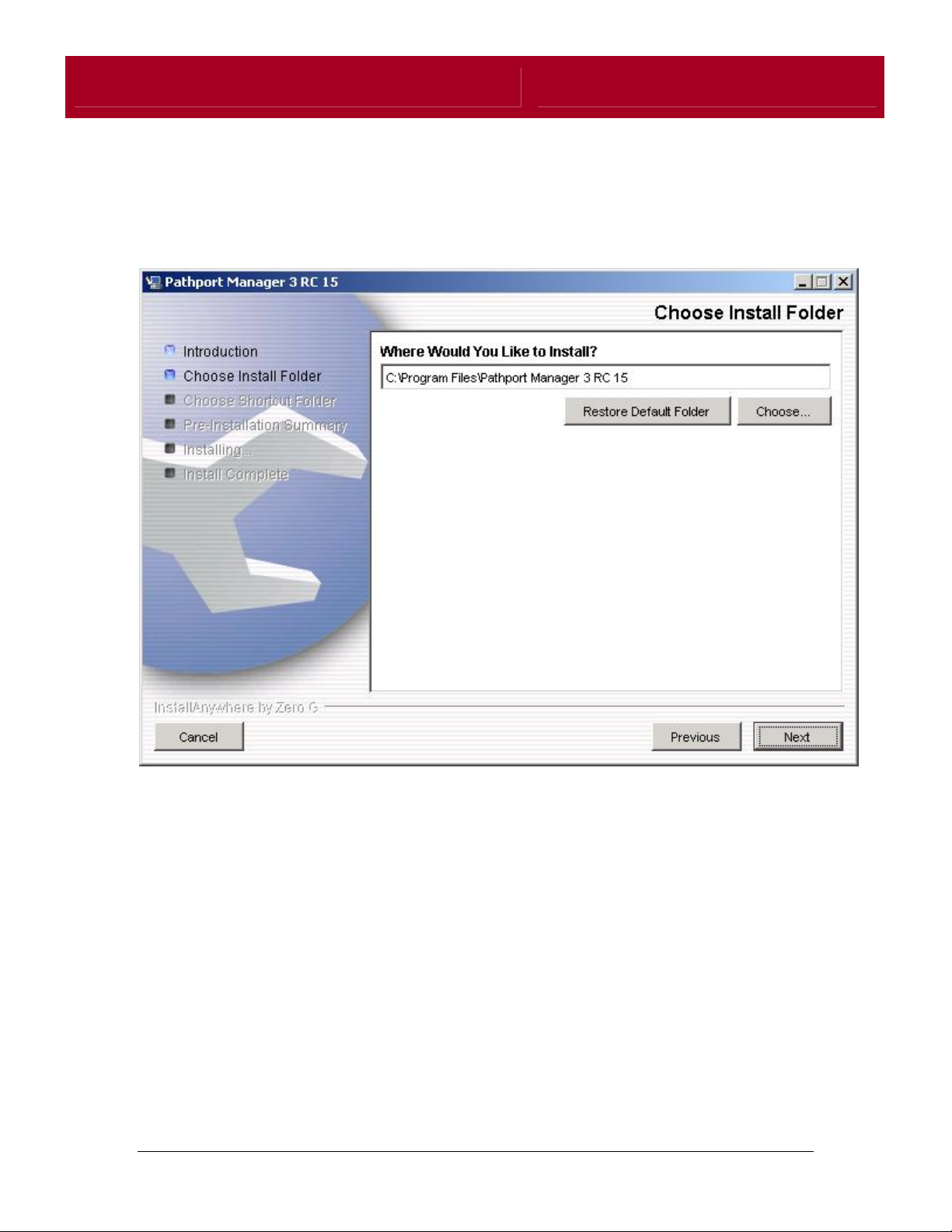
Screen 2:
Screen 2 of the installation will prompt you to specify a folder location for the
installation of Pathport Manager. If you are unsure of where to install Pathport
Manager, it is recommended that you install Pathport Manager in the location
specified by the installer .
4
Page 5
Pathport Manager User’s Guide
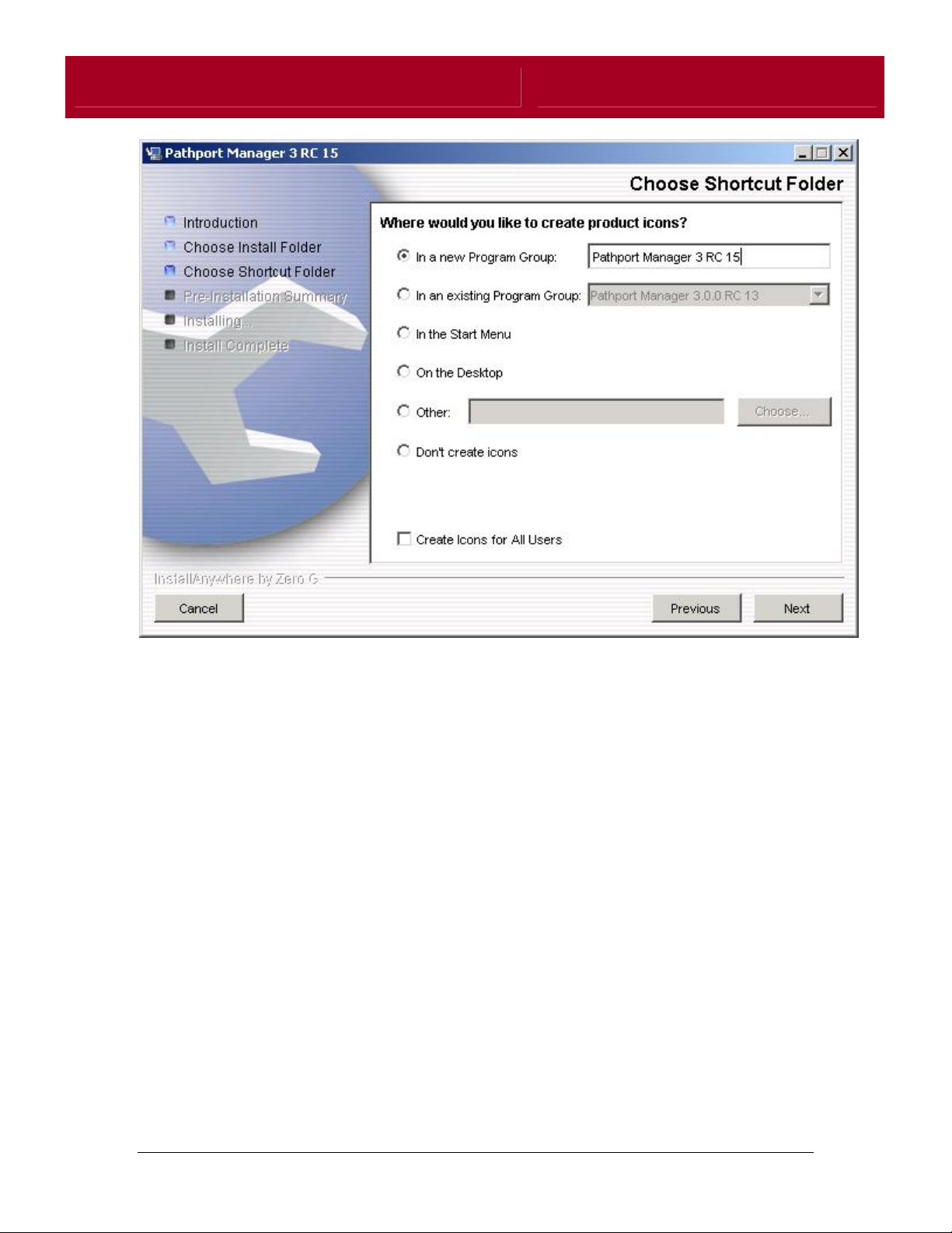
Screen 3 allows you to specify where you would like shortcuts created for
launching Pathport Manager. The default action is for the installer to create a
new program group within the Windows Start Menu containing the Pathport
Manager launcher. You can also specify that icons be added to the desktop, or
that the launcher be placed in an existing program group.
5
Page 6
Pathport Manager User’s Guide
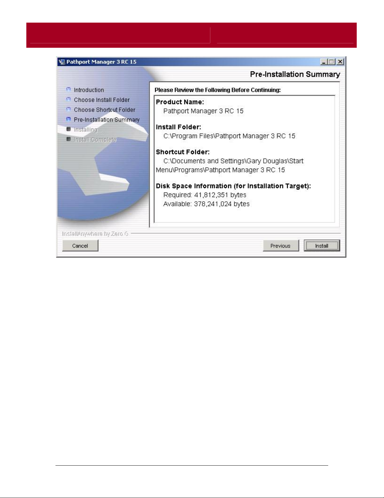
The fourth screen is a summary of all of the configuration options given to the
installer. If you wish to change any options before proceeding with the
installation, you may click the Previous button to go back to the last screen. If all
of the options are correct, clicking the Install button will complete the installation.
6
Page 7
Pathport Manager User’s Guide
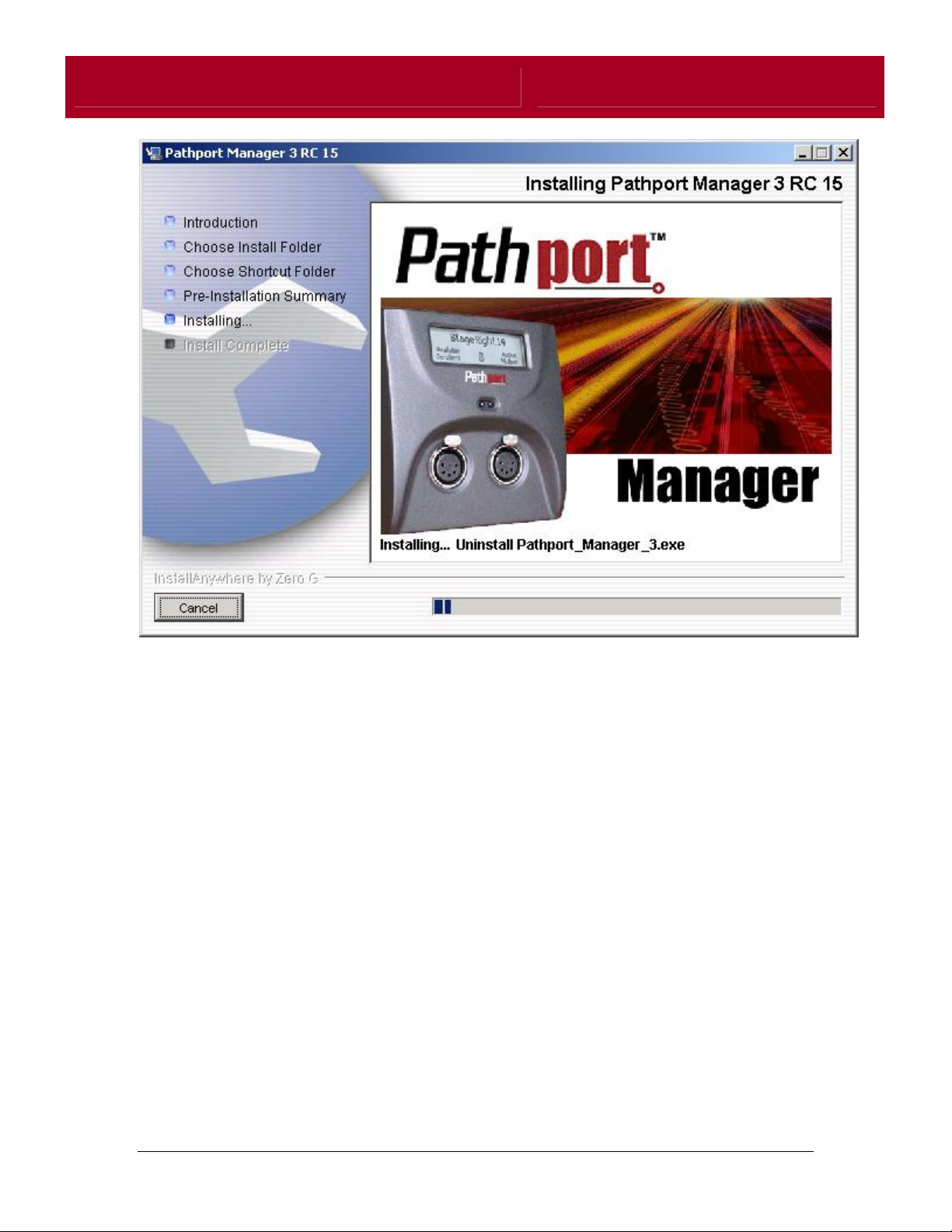
As Pathport Manager is being installed, the installer will display its' progress.
Pressing Cancel at any time during this phase will stop the installation and
clean-up any installed files. This process can take a few minutes, so it is
important to be patient while the installer is working.
7
Page 8
Pathport Manager User’s Guide
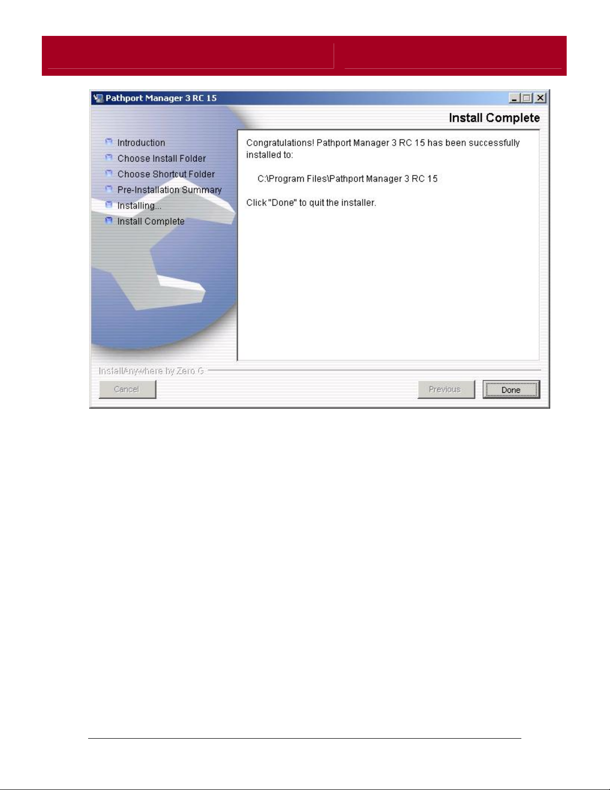
Once the program is installed, the installer will notify you that the process was
successful, and will review where the program was installed. Pressing Done will
finish the installation.
You are now ready to launch Pathport Manager.
8
Page 9

Pathport Manager User’s Guide
SETTING UP YOUR PC
From the factory, Pathports are configured to search the network for Pathport
Manager to receive their first boot settings, as well as the latest operating
software.
The first step in getting the system up and running is to configure your
computer's network connection for Pathport traffic. It is recommended that the
Pathport network be configured to operate on the 10.x.x.x. class A internal
subnet. This ensures that the data sent out by Pathports is not automatically
routed onto public networks. For Pathport Manager to function correctly, the
network interface used to communicate with the system must be addressed and
configured to operate within this subnet.
If you are an advanced network user you can jump immediately to Advanced
Network Setup or Starting Your Pathport System
If you are not sure if you are an advanced user, the following instructions will help
you set up your computer with the settings most likely to work - the first time.
The settings may be changed as necessary in the future, but will guarantee a
smooth initial startup.
First, please select your operating system for instructions on setting up your
computer's network interface:
Windows XP
Windows 98
Windows 2000
Mac OS X
Linux
Windows XP Users:
Choose <START><CONTROL PANEL> to open the Windows XP Control Panel.
Select "Network Connections"
Under " LAN or High Speed Internet", double click "Local Area Connection"
When the "Local Area Connection Status box pops up, click the "Properties"
button.
Select the "General" tab, then select "Internet Protocol (TCP/IP)".
9
Page 10

Pathport Manager User’s Guide
Click the "Properties" button.
Select the "Use the following IP address" radio button, and specify 10.0.0.5 as
the IP address.
Specify 255.0.0.0 for the subnet mask.
Do not specify any addresses for the DNS options. These are unnecessary for
Pathport Manager.
Click the "OK" button to complete the setup process.
You should now Start Pathport Manager.
Windows 98 users:
Choose <START><SETTINGS><CONTROL PANEL> to open the Windows 98
Control Panel.
Select "Network"
Select the "Configuration" tab.
In the list if network components, select " TCP/IP ->[your network card]", then
click the "Properties" button.
NOTE: If the TCP/IP option does not exist for your network interface, click the
"Add" button, and install the TCP/IP protocol. (Located in the "Microsoft" list of
protocols.). After installing the protocol, Windows will ask for your Windows
installation disks, and will also require a system re-boot. After this is complete,
just follow these instructions again to set up the interface.
In the TCP/IP properties dialog that pops up, select the "IP Address" tab.
Select the "Specify an IP address" radio button, and specify 10.0.0.5 as the IP
address.
Specify 255.0.0.0 for the subnet mask.
Click the "OK" button.
You should now Start Pathport Manager.
10
Page 11

Pathport Manager User’s Guide
Windows 2000 users:
Choose <START><SETTINGS><NETWORK AND DIAL UP CONNECTIONS> to
open the network configuration dialog.
Select the connection named "Local Area Connection", and from the File or
Right-Click menus select "Properties".
Select the "General" tab, then select "Internet Protocol (TCP/IP)".
Click the "Properties" button.
Select the "Use the following IP address" radio button, and specify 10.0.0.5 as
the IP address.
Specify 255.0.0.0 for the subnet mask.
Do not specify any addresses for the DNS options. These are unnecessary for
Pathport Manager.
Click the "OK" button.
You should now Start Pathport Manager.
Mac OS X Users:
From the Dock or in the Finder under "Applications", open "System Preferences".
Under "Internet and Network", Open "Network"
Select the "TCP/IP" tab.
In the drop-down box labelled "Configure", select "Manually"
In the box labelled "IPaddress", enter 10.0.0.5
In the box labelled "Subnet Mask", enter 255.0.0.0
Click the "Apply Now" button to complete the changes.
You should now Start Pathport Manager.
11
Page 12
Pathport Manager User’s Guide
Linux Users:
As root, enter the following:
ifconfig eth0 down
ifconfig eth0 netmask 255.0.0.0 10.0.0.5
ifconfig eth0 up
Where eth0 is the name of your network interface.
You should now Start Pathport Manager.
STARTING PATHPORT MANAGER
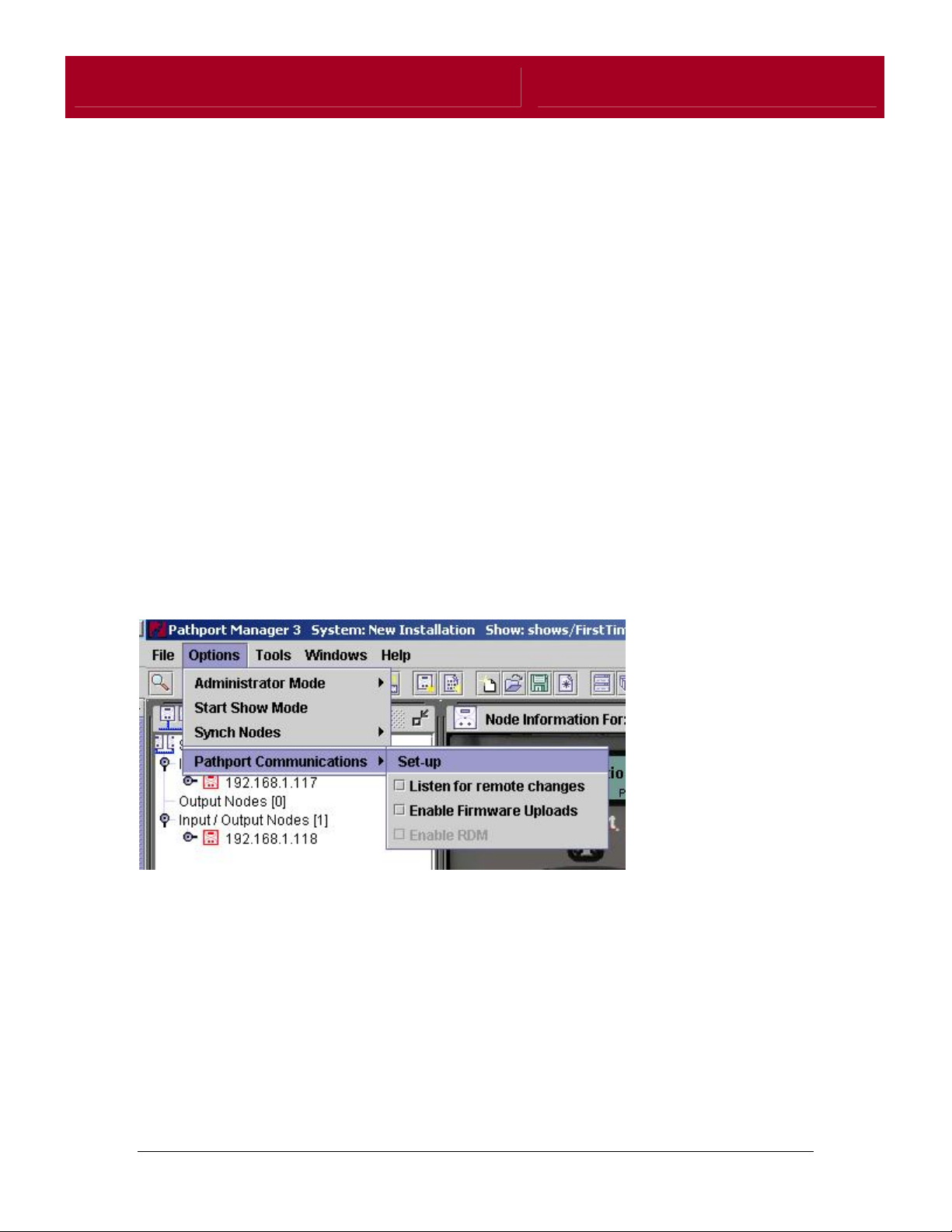
When Pathport Manager runs for the first time, it locates Network Interfaces
present on the host computer and binds to the first interface found. This may not
guarantee that Pathport Manager chooses the correct interface connected to
your Pathport network( as configured previously). To change the network
interface Pathport Manager uses, select Options -> Pathport Communications->
Set-Up on the Menu bar:
12
Page 13
Pathport Manager User’s Guide
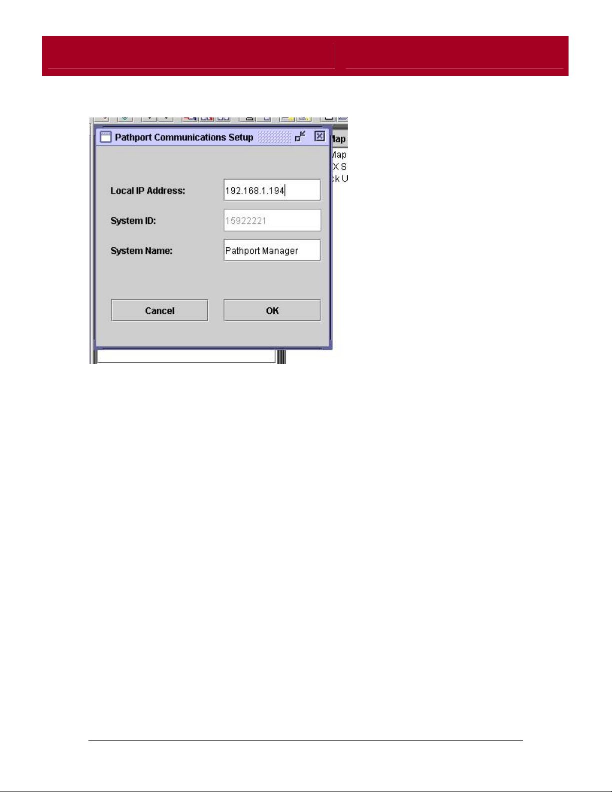
The Pathport Communications Setup panel will pop up:
If "10.0.0.5" is not listed in the Local IP Address box, enter it and click OK.
Note: Depending on the operating system being used, it may be necessary to re-
start Pathport Manager before Pathport Nodes are discovered.
Once Pathport Manager has been set up to communicate using the correct
network interface and IP address, you can now start your Pathport System for
the first time.
13
Page 14

Pathport Manager User’s Guide
STARTING UP YOUR PATHPORT SYSTEM
From the factory, Pathport nodes are configured to continually re-boot until they
receive new IP addresses and operating software from Pathport Manager. This
is to prevent mismatched software versions, as well as conflicting network
addresses.
IP Addresses:
Every device on a Pathport network ( or any IP network) must be assigned a
unique IP address. This address acts as a unique identifier for a device as long
as it is connected to a given network. Many networks are configured with servers
that assign these addresses dynamically to help reduce the chance of two
devices having the same address. Pathport nodes rely on being configured by
such a server the first time they are run. When run in Windows, Pathport
Manager contains one such server, called a "BOOTP Server".
Firmware Uploads:
Pathport nodes also rely on a special server to provide them with operating
software the first time they are run. This server uses a protocol called TFTP ( or
Trivial File Transfer Protocol) to send the firmware file to the nodes. Within
Pathport Manager, a TFTP server is programmed to search within the "firmware"
folder for the firmware file that the Pathport requests - normally a file named
"ppimage.bin". This file is required in order to start the Pathports.
Starting the Pathport Nodes (Windows Users only):
1. Start Pathport Manager.
2. Make sure your Pathport nodes are not connected or not powered up.
3. Next, make sure you have set up your PC's IP address correctly within
Pathport Manager.
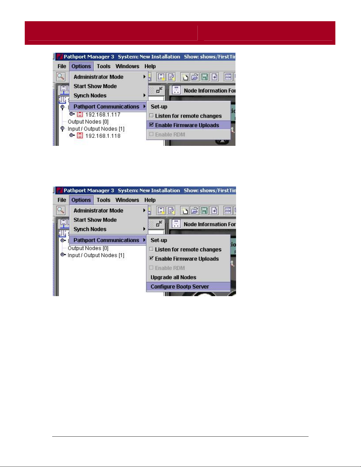
4. From the Options Menu, select "Pathport Communications" , then "Enable
Firmware Uploads" . A checkmark will appear in the box within the menu
item:
14
Page 15
Pathport Manager User’s Guide
5. Re-start Pathport Manager to enable the servers.
6. Configure the BOOTP server by selecting "Pathport Communications" ,
then "Configure Bootp Server:
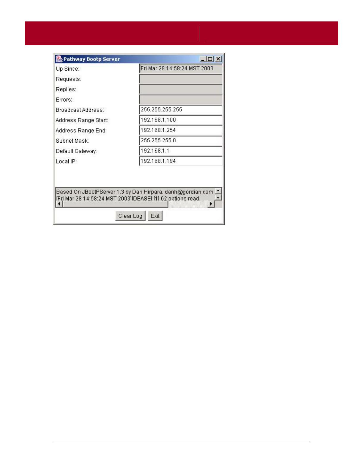
7. The Bootp Server window will open:
15
Page 16
Pathport Manager User’s Guide
8. Make sure that your PC's IP address is correctly noted in the "Local IP"
box. If it is not, enter it and press enter. The Pathport will use the Local
IP parameter to find out where to request firmware from.
9. Enter an IP range that does not include your PC's IP address. For
example, if your PC's IP address is 10.0.0.5, you should enter 10.0.0.101
into the Address Range Start box, and 10.255.255.254 into the Address
Range end box.
10. If your network contains multiple subnets connected by a router, you can
also specify a subnet mask and a default gateway to facilitate routing.
11. Once you have configured these parameters, click "Exit".
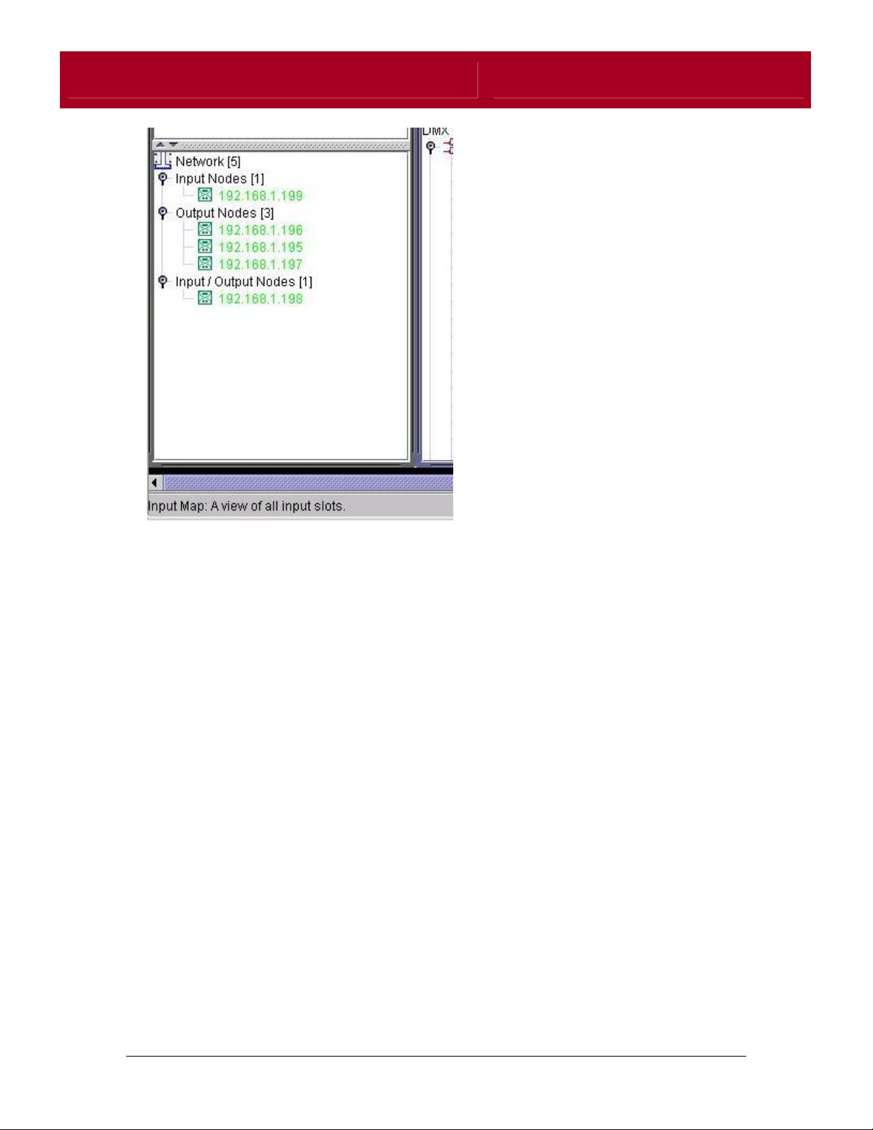
12. Connect your Pathport network and power up your nodes. They should all
boot normally and show up (after a few seconds) in Pathport Manager's
network tree view. The nodes will appear as green icons with green text
denoting that they have not already been added to the show.
16
Page 17
Pathport Manager User’s Guide
13. Once all of your Pathports have started, you can disable the servers for
future runs of Pathport Manager by de-selecting "Enable Firmware
Uploads" from the "Pathport Communications" item within the tools menu.
17
Page 18
Pathport Manager User’s Guide
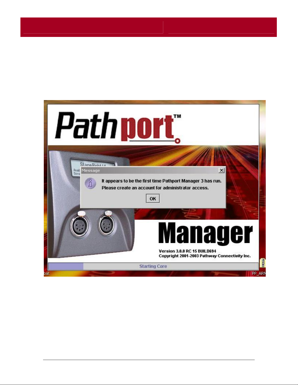
RUNNING PATHPORT MANAGER FOR THE FIRST TIME:
The first time Pathport Manager is run, the program will require that an
administrator account be created. A message box will pop up to notify you of
this process.
18
Page 19
Pathport Manager User’s Guide
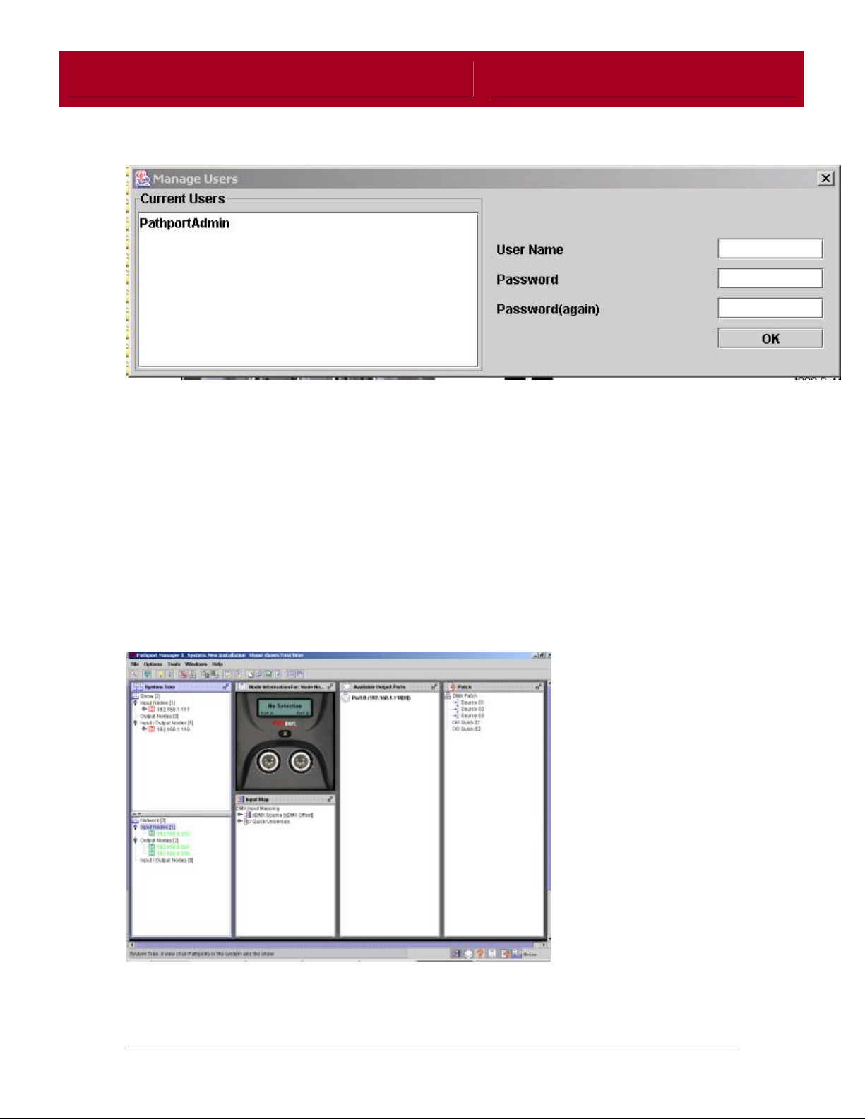
Pressing OK will bring up the "Manage Users" dialog:
To create an administrator account, simply enter a user name, then a password.
You will need to verify the password as well. This will be your login for future
versions of Pathport Manager.
NOTE: As of the writing of this manual, security and user management has
been temporarily disabled. All features will be available to all users of
Pathport Manager, regardless of administrator status. This will be changed
for version 3.0.1 and higher.
Once all of the first run items have been completed, the main Pathport Manager
window will open:
19
Page 20

Pathport Manager User’s Guide
When Pathport Manager starts, it automatically queries the network for all of the
connected Pathports. It then queries each unit for its' configuration information. If
Pathport nodes are detected on the network, "On-line" will appear in the bottomright corner of the window.
Pathport Manager's automatic discovery process should be visible in the Network
Tree. If there is no visible activity in the Network Tree, or if it remains empty, this
is a sign that there is a problem with the network setup. Please check your
network settings and re-start Pathport Manager.
If all of the connected Pathports are visible in the Network Tree, Pathport
Manager is now ready for its' first use.
When the program is first run, a default show file, called FirstTime is loaded. This
show file contains a number of Pathports that will not be present on the
network. The first step in setting up the system is to remove all of these nodes
from the show. To do this, right-click on any node in the Show Tree, and select
"Remove All Nodes From Show". A dialog box will pop up to ask for
confirmation. Click "OK".
The next step is to add all of the connected Pathports to the show. This is done
by right-clicking any node in the Network Tree, and selecting "Add All Nodes To
Show".
20
Page 21

Pathport Manager User’s Guide
Once all of the nodes are added to the show, it is important that each DMX input
port is assigned a unique xDMX source address. (Overlapping sources will
cause flickering and data contention).
DMX input mapping is set up within the input map frame. To change an input's
source address, simply click the input port anywhere it appears, and drag it to a
different source within the xDMX Source tree.
If inputs are overlapping, Pathport Manager will replace the icon of the problem
source with a notification icon.
When a source is OK, a corresponding universe will appear in the Patch Frame.
21
Page 22

Pathport Manager User’s Guide
To connect an output to a source simply drag an output port to a universe and
drop it on top of a universe.
The last step is to clear the existing patch information from the nodes. The
Pathports are shipped patched to the default configuration, which allows for outof-the-box performance without the need for Pathport Manager. This patch HTP
merges all A inputs and connects them to all A outputs, and all B inputs to all B
outputs. This is done via the "Quick Patch" system.
If this configuration is not desired click the "Clear Patch" button on the toolbar.
This will unassign the default patch and make the system ready for new patches.
When the patch is cleared, all output ports will be moved to the "Available
Outputs" window. To disconnect a single output, you can also drag it from the
universe it is assigned to (within the Patch Frame) and drop it onto the "Available
Outputs" window.
The system is now ready for operation.
22
Page 23

Pathport Manager User’s Guide
AN INTRODUCTION TO PATHPORT MANAGER
Introduction
Welcome to Pathport Manager 3! This software will provide you with a powerful
yet easy-to-use tool for managing, configuring, and testing your Pathport system.
Pathport Manager and your Pathport system will help you efficiently manage
lighting control data throughout your facility.
How does it work?
A Pathport system is a data manager that utilises a distributed network of
devices that are capable of adding data to, or reading data from the network.
Because the system is distributed, every device has access to all of the
information being carried on the system, and can be configured to use the data
differently than any other device on the system. The ability of every device to
individually process data provides the amazing power of Pathport.
By distributing the processing of network data, a Pathport system is able to grow
and re-configure to meet the changing needs of a facility with the minimum
possible effort and expense.
No really, how does it work?!?
Every DMX input port or Pathport Alliance controller adds control data to a
32768 channel universe of xDMX channels on the network. These channels are
added in blocks of 512 channels called "Sources".
Output ports, or controllable Pathport Alliance devices, can then be configured to
read individual or multiple channels from the xDMX universe, and use them in a
particular way. Just like most DMX512 devices can be patched to an individual
DMX channel, every output channel on every Pathport DMX output port can be
patched to an individual xDMX channel.
Patching is done by creating "Universes" within Pathport Manager. A universe is
meant to be the complete grouping of xDMX channels that a Pathport DMX
output port sends to all of the equipment that is connected to its DMX output. A
Universe may be the entire DMX data stream from a single controller, or a
complex combination of DMX levels from a number of sources.
Once a universe is created, regardless of its complexity, an output port can then
be configured to send that universe as DMX data by patching it within Pathport
Manager.
Entire DMX universes can be patched without having to painstakingly construct
universes from scratch. Whenever an input is configured to place its DMX
23
Page 24

Pathport Manager User’s Guide
channels at a given xDMX source address, a universe is automatically created
for those channels, saving a great deal of time.
What about merging and prioritizing?
Pathport universes can be created using a priority system that allows up to 8
xDMX channels to be patched to a single DMX output channel. Each xDMX
channel patched to an output channel has a priority level associated with it that
tells the Pathport how to handle each channel. If two or more channels have an
equal priority, they will be HTP merged. If the priorities are not equal, the active
xDMX channel with highest priority will be processed and sent as DMX.
Configuration?
Pathport Manager is aware of all Pathport nodes and Pathport Alliance devices
on the system. Pathport Manager knows all there is to know about Pathports,
and allows you to change a vast number of configuration options. Changing
these parameters has all been grouped in the Pathport Properties box.
Everything from advanced IP parameters to DMX output port speed can be
configured from there.
24
Page 25

Pathport Manager User’s Guide
GETTING STARTED WITH PATHPORT MANAGER
If you've plugged your PC into your Pathport network and the available nodes
appear in your Network Tree in Pathport Manager, you are ready to start using
Pathport Manager right away. If you don't see any nodes, you ll have to be a bit
more patient and carry on with Setting Up your Computer.
If you can see nodes in Pathport Manager's Network Tree, here's what you need
to know for a quick start.
You will see 5 windows on your initial start up:
System Tree
Pathport Properties
Input Map
Patch
Available Output Ports
The System Tree indicates your connected network and nodes, and your show is
the configuration of nodes you want to use at this time. Shows can be saved to
disk for future use or backup and archiving. To configure or patch Pathport
nodes, they must have already been added to your Show. Right click on any
node in the Network section of the System Tree and select "Add All Nodes to
Show". Now you will be able to patch and configure your nodes.
The Input Map will show how all of the Input ports (DMX Sources) connected to
your system are configured.
The Patch window shows all of the possible xDMX or "Quick" Universes
generated by DMX sources in your show. This will also show how all of the
Output Ports are currently configured.
NOTE: As of the writing of this manual, Pathport Manager will not import
the patch from a system on first run. If a system has been patched
previously to custom universes, the previous show file must be loaded in
order to view the current patch.
The "Available Output Ports" window displays all of the un-patched Output Ports
in your show. They disappear from this window and reappear in the Patch
window when patched.
25
Page 26

Pathport Manager User’s Guide
To patch your nodes:
1. Click and hold on the universe you wish to patch in the Patch window.
2. Drag it over to the Available Output Ports window, until it's over the port
that you wish to connect to.
3. Let go. The output port you have chosen will disappear from the available
output ports window and reappear in the Patchwindow.
4. Alternatively, you can drag an Output Port to the DMX Universe you want
to patch to.
Either method achieves the same result. Use the one that suits you best.
To Label Nodes:
1. Click on any node in the Show section of the System Tree.
2. A Pathport graphic representation will change to reflect yur selection.
3. Right mouse click on the LCD display in the illustration and select
"Properties" in the popup menu. A properties frame will pop up.
4. Enter a new node name in the "Node Name" box and press enter.
5. You can also select each of the port tabs to access parameters for each
port, including port name, DMX Speed, and others.
Quick Configuration Tip!
Pathport nodes are shipped with a Quick patch that does not require
configuration from a PC. This can be used to quick start a system or troubleshoot
an installation.
If Pathport nodes have not been patched by Pathport Manager, they will default
to an A->A, B->B patch. That is, any active DMX source (console or tester) that is
plugged into the A port of a Pathport Input node, will automatically be routed to
all Output node A ports. Similarly, any B input port will automatically be routed
to all Output node B ports. If a second source is plugged into another A input
port when a valid DMX source is connected to an A input elsewhere, the A
sources will be HTP merged by the system. Any B input port will operate in the
same way. Both A and B may have up to 8 active sources each, at any time.
There are 64 Quick Universes available within Pathport Manager, each having
the same rules as above. By default, all A ports are patched to Quick 1 and all B
ports are patched to Quick 2.
26
Page 27

Pathport Manager User’s Guide
ADVANCED NETWORK SETUP
Pathports and Pathport Manager are capable of living on any subnet, public or
private. However, use of Pathports on a public network is not recommended due
to large traffic volumes created by the Pathport. Due to varying complexities in
computer and network configuration and setup, Pathport Manager may require
additional setup before it is ready to communicate with a Pathport Network.
Using Pathport Manager with multiple Network Interfaces:
Pathport Manager is capable of running on a computer with multiple network
interfaces. Due to operating system and routing limitations, however, Pathport
Manager is only able to communicate with Pathport networks on a single
interface at any time.
When Pathport Manager runs for the first time, it locates Network Interfaces
present on the host computer and binds to the first interface found. This may not
guarantee that Pathport Manager chooses the correct interface connected to
your Pathport network. To change the network interface Pathport Manager uses,
select Options -> Pathport Communications-> Set-Up on the Menu bar:
27
Page 28

Pathport Manager User’s Guide
The Pathport Communications Setup panel will pop up:
To set the correct network interface enter the IP address of the network interface
connected to the Pathport network in the Local IP Address box, then press the
OK button. Pathport Manager will attempt to discover all of the Pathport nodes
on the new interface as soon as the panel is closed.
Note: Depending on the operating system being used, it may be necessary to restart Pathport Manager before Pathport Nodes are discovered.
Use of Pathports and Pathport Manager with a BOOTP server:
Many operating systems rely on the use of Dynamic IP allocation for configuring
Local Area Network connections. If Pathports and Pathport Manager are used
with an external BOOTP server, Pathport Manager's saved local IP address
parameter may become 'out of sync' with the IP address assigned to the
machine. If no nodes are discovered after re-starting your machine ( but they
were discovered previously) it is likely that your PC's IP address, or the IP
address of your Pathports may have changed. To remedy the situation, first
verify the computer's IP address, then enter it as outlined above.
28
Page 29

Pathport Manager User’s Guide
PATHPORT MANAGER'S INTERNAL WINDOWS
Pathport Manager's main window consists of a number of internal panels,
organized by function. This section will explain each of these in detail.
System Tree:
This is the panel where all of the selection of nodes is done. It also provides a
system wide view of all of the Pathports currently connected to the system. This
panel is separated into two tree structures, the Show Tree, and the Network
Tree.
29
Page 30

Pathport Manager User’s Guide
Show Tree:
The Show Tree represents all of the
Pathports that are currently assigned to
the show. This tree represents the current
configuration for the show, but may not
represent what is present on the network.
The Show Tree is where all modifications
to Pathport properties begin. When a
Pathport is selected in the Show Tree, it is
selected for editing in either the graphical
editor, or the Properties window.
There is also a context sensitive right-click
menu for each Pathport in the Show Tree
that allows for removing the node from the
show, or binding an offline Pathport to a
network node. A node's status in the
system is shown by the node's icon in the
Show Tree:
Network Tree:
The Network Tree provides a quick
system-wide look at all of the Pathports
connected to the network. This tree does
not allow for editing or viewing node
properites, but does provide a right click
menu for a node's assignment to or
removal from the current show.
30
Page 31

Pathport Manager User’s Guide
Input Map:
The Input Map displays the configuration of
all DMX input ports connected to the
system. Each input port's xDMX offset, as
well as its Quick Universe number, are
configured within the Input map's tree.
The Input Map will also display status for all
sources and quick universes, depending on
the number of DMX inputs connected.
31
Page 32

Pathport Manager User’s Guide
Pathport Properties Window:
This is a
quick, nongraphical
view of the
currently
selected
Pathport's
properties,
activated by
selecting
"Properties"
from the
Pathport
right-click
menu.
Values for all
of the
Pathport's
configurable
parameters
can be
changed in
real time by
selecting or
entering a
new value
and pressing
enter.
32
Page 33

Pathport Manager User’s Guide
Graphical Pathport Properties window:
This window is a graphical look at the
current configuration of the selected
Pathport. It gives a quick look at the node's
LCD display and soft labels, as well as
allows for editing of all of the node's
properties.
To access the editing features of this
window, right click the element that is to be
edited,and a menu will pop up. The LCD
display, the IR transceiver, as well as the
DMX connectors all have associated
menus for changing the properties specific
to those parts of the Pathport.
33
Page 34

Pathport Manager User’s Guide
Available Output Ports window:
The Available Output Ports window contains
all un-patched outputs in the show. Each
output is represented by an XLR connector
icon, and is labelled with the port's soft
label, as well as the name label of the
Pathport it is part of.
To patch an output, simply drag and drop it
onto a universe in the Patch window.
Outputs are dynamically added as
Pathports are added to the show.
34
Page 35

Pathport Manager User’s Guide
Patch window:
This window displays a tree-view of the
system's DMX patch. An output can also
be re-patched to a different universe by
dragging it from its current universe and
dropping it on any universe within this
window.
This window displays all of the universes
that have been defined for the current
show. Universes are dynamically added to
this window as input Pathports are added
to the show, and their xDMX source
number is properly configured.
Custom universes may also be created to
utilize the Pathport's channel patching and
merging functionality. A custom universe
is created by clicking the "Create new
Universe" button on the toolbar. This
button pops up another window that allows
for command-line patching of network data
slots to DMX output channels (See
"Patching" for more information) Any
universe may be assigned to any output
by dragging it from the Universe window
and dropping it on any visible output.
35
Page 36

Pathport Manager User’s Guide
CREATING UNIVERSES
The first step in creating a universe is identifying within the input map which
sources you would like to patch channels from. The source number for all of the
inputs sourcing channels for a given universe is key to successful patching.
Once the source numbers have been identified, click the "Create New Universe"
button on the toolbar. The "Create New Universe" window will open:
The Create New Universe frame consists of a table of cells for xDMX channels, a
name entry box, and a command line. Each row in the channel table represents
a single DMX output channel. The columns represent the entire group of xDMX
channels that can be patched.
36
Page 37

Pathport Manager User’s Guide
Each cell in the table represents a single Patch Element, which is defined as a
combination of an xDMX channel at a specific priority.
Universes are created by using the command line to add patch elements to the
universe.
Patch Elements:
A Patch Element assigns a DMX output channel and a priority level for a single
xDMX channel. If data for that xDMX channel is received by the Pathport, the
data is then processed at the stated priority level.
A Universe is a grouping of Patch Elements that define how the Pathport output
port handles xDMX data being transmitted over the network. Universes can be
comprised of as few as one element, or as many as 4096 (in the current Pathport
release).
Priority:
Priority defines how a Pathport Output port processes incoming xDMX data
when there are multiple patch elements assigned to a single DMX channel.
Priority is what defines both HTP merges and "backup" failover patches within a
pathport network.
HTP Merges are created by assigning equivalent priority to two or more patch
elements for a DMX channel. When two or more of the assigned xDMX channels
are active, the highest level of all of the xDMX channels assigned will be
transmitted.
Backup patches, or xDMX prioritization, is accomplished by assigning different
priority levels to two or more patch elements for a DMX channel. The active
xDMX channel with the highest assigned priority will be transmitted as DMX at
the assigned DMX channel.
The priority system can also allow for complex universes, able to prioritize groups
of HTP merged channels. Using combinations of equal and differing priority
levels, it is possible to build a universe that can actively switch between groups of
HTP merged source channels.
Since each DMX channel may be assigned up to 8 patch elements, there are up
to 8 different priority levels available within a universe. Pathport Manager will
assign these priority levels automatically as patch elements are created. How
this priority is assigned depends on the command line syntax used.
37
Page 38

Pathport Manager User’s Guide
The Command Line:
The universe command line is roughly based on standard lighting console
patching syntax, and is meant to be done on a standard numeric keypad. The
key mapping is as follows:
Button Command
0 through 9 Numeric entry buttons - 0 through 9
* AT
- THRU
/ PRIORITY
+ MERGE
Enter Enter
. DOT Source Designator
To enter a command, simply enter the DMX output channel or range of
channels, followed by the AT symbol, followed by the xDMX channel or channels
to patch. The rule is:
DMX channel <AT> Output Channel(s)
It is possible to use a single command line to create any where between 1 and
4096 patch elements within a universe. Multiple command line entries will add
elements to the universe in the order they are entered.
A few simple Examples:
To add a single patch element to a universe, assigning xDMX Source 1, channel
1 to DMX channel 1, enter:
1*1<ENTER>
or
1*1.1<ENTER>
A patch element will be added at the highest priority (8) for channel 1:
38
Page 39

Pathport Manager User’s Guide
To patch all 512 DMX channels to xDMX Source 1, Channel 1, you can enter:
1-512*1<ENTER>
or
1-512*1.1<ENTER>
512 patch elements will be created at the highest priority, one for each DMX
channel:
39
Page 40

Pathport Manager User’s Guide
While this universe is probably not very useful, ranges of channels can be
expressed for both the DMX channel side of the command, as well as the xDMX
channel side.
To Patch DMX Channels 1-512 to xDMX Source 1, channels 1-512 you would
enter:
1-512*1-512<ENTER>
or
1-512*1.1-1.512<ENTER>
40
Page 41

Pathport Manager User’s Guide
Note the use of the "-" THRU operator after the *(AT) symbol. In actuality the
number after the THRU operator on the xDMX side is optional, as Pathport
Manager will calculate the number of xDMX channels to patch using the DMX
side of the command. The same assignments can be made by entering the
following commands:
1-512*1-<ENTER>
or
1-512*1.1-<ENTER>
While this universe is a duplicate of the universe that Pathport Manager will
create automatically for Source 1, it is an important starting point for creating
more complex universes.
Once Patch Elements have been added to a universe, they can be replaced by
entering another command.
41
Page 42

Pathport Manager User’s Guide
To change the xDMX channel assignment for DMX Channel 1 through 12 to
source 2 channels 1-12 (xDMX 513-524) simply enter the following command:
1-12*513-524<ENTER>
or
1-12*2.1-2.12<ENTER>
or
1-12*513-<ENTER>
or
1-12*2.1-<ENTER>
This changes the universe to:
To remove all of the patch elements for a DMX channel( or a range of channels),
simply enter a patch element patching the channel(s) to xDMX channel 0. This
will clear the channel completely.
42
Page 43

Pathport Manager User’s Guide
Reverse Ranges:
Ranges of DMX or xDMX channels may also be entered in reverse order for
convenience. Entering:
512-1*1.1-1.512<ENTER>
or
1-512*1.512-1.1<ENTER>
will produce the same result - completely reversing the channel order of Source
1.
NOTE: To use a descending order range on the xDMX side of a command, both
the start and end xDMX channel must be specified.
The DOT (.):
As shown in the above examples xDMX channels can be entered as an absolute
value (from 1-32768) or as SOURCE<DOT>CHANNEL. This helps speed up
Universe creation by eliminating the need to calculate xDMX offsets. The DOT
can only be used on the xDMX side of a command.
Summary:
Here are the rules for creating universes that have been covered so far:
1. Universes are simply groups of Patch Elements instructing a Pathport
Output Port how to process incoming xDMX data.
2. A Patch Element contains an xDMX channel and a priority level, and is
assigned to a DMX Output channel.
3. Patch elements are created using the command line with the syntax
OUTPUT<AT>xDMX
4. Without using any of the HTP or Priority operators, each command
creates a new set of patch elements at the highest priority for the DMX
channels specified. Patch elements created replace any existing element
already created for a DMX channel.
5. Patch elements may be created one-at-a-time, or in multiples by using the
THRU (-) operator on either side of the command.
6. xDMX Channels maybe expressed in absolute value, or using the DOT
operator.
7. Ranges may be expressed in ascending or descending order.
43
Page 44

Pathport Manager User’s Guide
BUILDING MERGES AND BACKUPS
Merges and backups are created using an extension of the command line that
allows for creating multiple Patch Elements for a single DMX output channel.
The extensions use the HTP (+) and the Priority (/) operators to determine how
to assign a priority level to each Patch Element created.
The HTP (+) operator makes the priority of adjacent Patch elements equal, while
the Priority (/) operator reduces the priority level each time a patch element is
created.
Differences in priority levels between patch elements are expressed by
differences in color between each patch element in the table. Hovering the
mouse cursor over a Patch Element will also pop up a description of the element,
including its' priority.
Patch Element priority can range from 8 (Highest Priority) to 1 (lowest priority).
As priority decreases, the color of the patch element is darkened. Patch
elements that have equivalent priority will be the same color.
Note: Placement of the element within the table does not denote priority due to
the fact that two or more elements may have priorities that are equal.
The command syntax for creating complex patches is:
OUTPUT<AT>xDMX[Priority or HTP]xDMX[Priority or HTP]xDMX..... with up
to 8 xDMX assignments.
To create a new Universe where xDMX Source 1, Channel 1, and Source 2
Channel 2 are HTP Merged to create DMX output channel 1, enter:
1*1+513<ENTER>
or
1*1.1+2.1<ENTER>
44
Page 45

Pathport Manager User’s Guide
This will create:
Note that both of the patch elements created are the same color, and will each
describe having a priority of 8 when the mouse cursor is placed over top.
To create an equivalent prioritized universe, where Source 1, Channel 1 has a
higher priority than Source 2, Channel 1 enter:
1*1/513<ENTER>
or
1*1.1/2.1<ENTER>
45
Page 46

Pathport Manager User’s Guide
Which will create:
Note that the colors are different and that xDMX 513 shows a priority of 7.
While the 2 universes above may not be very useful, ranges may also be
employed to assign multiple groups of xDMX channels to this universe.
To create a universe that HTP merges all of xDMX sources 1 and 2, enter:
1-512*1.1-1.512+2.1-2.512<ENTER>
or
1-512*1.1-+2.1-<ENTER>
46
Page 47

Pathport Manager User’s Guide
This will create:
To create a universe that Prioritizes all of xDMX sources 1 and 2, where Source
1 has a higher priority than Source 2, enter:
1-512*1.1-1.512/2.1-2.512<ENTER>
or
1-512*1.1-/2.1-<ENTER>
47
Page 48

Pathport Manager User’s Guide
This will create:
Up to 8 xDMX channels or ranges can be specified, separated by either the HTP
or Priority operators. To create an HTP merge of the xDMX sources 1 through 8
you can enter:
1-512*1.1-1.512+2.1-2.512+3.1-3.512+4.1-4.512+5.1-5.512+6.1-6.512+7.1-
7.512+8.1-8.512<ENTER>
or
1-512*1.1-+2.1-+3.1-+4.1-+5.1-+6.1-+7.1-+8.1-<ENTER> --( Remember- the
end xDMX channel is optional!)
or even
1-512*1.-+2.-+3.-+4.-+5.-+6.-+7.-+8.-<ENTER> -- With the dot operator, if you
don't specify the start xDMX channel, 1 is assumed.
48
Page 49

Pathport Manager User’s Guide
The equivalent commands, replacing the HTP operator with the priority operator
1-512*1.1-1.512/2.1-2.512/3.1-3.512/4.1-4.512/5.1-5.512/6.1-6.512/7.1-
7.512/8.1-8.512<ENTER>
or
1-512*1.1-/2.1-/3.1-/4.1-/5.1-/6.1-/7.1-/8.1-<ENTER> --( Remember- the end
xDMX channel is optional!)
or even
1-512*1.-/2.-/3.-/4.-/5.-/6.-/7.-/8.-<ENTER> -- With the dot operator, if you don't
specify the start xDMX channel, 1 is assumed.
49
Page 50

Pathport Manager User’s Guide
These create:
Combinations of the HTP operators can also be used to create prioritized HTP
blocks within a universe.
For instance, if the HTP result of xDMX Sources 1 and 2 needed to have a
greater priority than the HTP result of xDMX sources 3 and 4 enter:
1-512*1.1-1.512+2.1-2.512/3.1-3.512+4.1-4.512<ENTER>
50
Page 51

Pathport Manager User’s Guide
This creates:
Note the 2 sets of 2 equal-priority columns of Patch Elements. The result of this
patch would mean that if either Source 1 or Source 2 became active, The DMX
transmitted would be the HTP result of Sources 1 and 2 -- Sources 3 and 4 would
be ignored. If Sources 1 and 2 were not active, the DMX transmitted would be
the HTP result of Sources 3 and 4.
EDITING AND APPENDING UNIVERSES
Just as in simple universe creation, the Patch Elements for a given DMX channel
can be replaced with a single channel.
Since it is sometimes inconvenient or undesirable to enter long commands into
the command line, Patch Elements can also be added to a universe without
deleting existing elements.
51
Page 52

Pathport Manager User’s Guide
Using the HTP or Priority operators as the first character in a command will
also allow patch elements to be added to those already created for a
channel.
Lets look at a previous example:
Add a single patch element to a universe, assigning xDMX Source 1, channel 1
to DMX channel 1:
1*1<ENTER>
or
1*1.1<ENTER>
52
Page 53

Pathport Manager User’s Guide
Now, if you want to merge xDMX 1 with Source 2 channel 1 you can enter:
+1*2.1<ENTER>
Resulting in:
53
Page 54

Pathport Manager User’s Guide
To prioritize those elements, with another at a lower priority enter:
/1*3.1<ENTER>
To create:
When appending data onto an existing universe, all of the rules for ranges and
the dot operator apply. You can append elements singularly or in groups, as
long as the total number of Patch Elements created for a single DMX channel
does not exceed 8.
54
Page 55

Pathport Manager User’s Guide
To append an HTP merge of xDMX Sources 7 and 8 at a lower priority onto the
above universe enter:
/1-512*7.1-7.512+8.1-8.512<ENTER>
To get:
Editing Universes:
It is quite easy to create a very complex universe by appending Patch Elements
onto existing universes. It is also very easy to make mistakes!
All user-created universes can be edited at any time by right clicking the universe
within the Patch window, and selecting "View Universe". When the Universe
window opens, the command line will be active and elements can be added or
deleted.
55
Page 56

Pathport Manager User’s Guide
NOTE: At this time there is no means of directly editing a Patch Element within
the table. Future versions of Pathport Manager will allow for the selection and
editing of Patch Elements directly, without using the command line.
Summary:
These are all of the rules for creating universes:
1. Universes are simply groups of Patch Elements instructing a Pathport
Output Port how to process incoming xDMX data.
2. A Patch Element contains an xDMX channel and a priority level, and is
assigned to a DMX Output channel.
3. Patch elements are created using the command line with the syntax
OUTPUT<AT>xDMX
4. Without using any of the HTP or Priority operators, each command
creates a new set of patch elements at the highest priority for the DMX
channels specified. Patch elements created replace any existing element
already created for a DMX channel.
5. Patch elements may be created one-at-a-time, or in multiples by using the
THRU (-) operator on either side of the command.
6. xDMX Channels maybe expressed in absolute value, or using the DOT
operator.
7. Ranges may be expressed in ascending or descending order.
8. Multiple patch elements can be created by separating xDMX channel or
range commands with the HTP or Priority Operators.
9. HTP and Priority elements can be used together within the same DMX
channel
10. Long commands can assign up to 8 Patch Elements to each DMX output
channel
11. Using the HTP or Priority Operators as the first character in a command
allows for adding elements to a universe.
12. User-created universes can be edited at any time from within the Patch
frame.
13. When the DOT operator is used, and a start channel not specified, 1 will
be assumed.
14. xDMX ranges need not specify an end channel after the THRU operator.
15. When the THRU operator is used on the DMX side of the command, and
no end channel is specified, an end channel of 512 is assumed.
56
Page 57

Pathport Manager User’s Guide
USING UNIVERSES
Once all of the desired elements have been added to a Universe, clicking the
"DONE" button will create the universe and make it ready for use. The Universe
will show up in the Patch window and can be patched to any output port.
If a universe has been patched to one or more outputs, and is then edited,
Pathport Manager will request that the Universe be re-sent to all ports currently
patched to it. This will ensure that the Output is behaving as desired.
PATCHING
The core functionality of the Pathport system is to patch incoming DMX signals to
output ports throughout the system. This is done in Pathport Manager either by
assigning an xDMX Universe (A group of incoming DMX levels), or a Quick
Universe to an output port.
Each DMX input port on the system is configured with both an xDMX source
number, and a Quick Universe number to facilitate managing the data being
received at that input port.
xDMX Universes:
While a universe typically represents the entire range of DMX channels from a
single DMX Source ( Console DMX output, etc..), Pathport Manager and
Pathport allow for the creation of complex "Custom Universes" comprised of
channels from any DMX source on the system. For convenience, Pathport
Manager generates a "Default Universe" for each correctly mapped DMX input
on the system. Source universes will be present as long as an input port is
"connected", and will allow for simple Source-to-Output patching of DMX
universes. These universes are not editable, nor can they be deleted without
removing the Pathport from the system. Custom universes, however, must be
user-created, and can be composed of any combination of DMX channels from
any Source. Custom universes can also prioritize or HTP merge any
combination of channels.
Universes, whether custom or Source universes, can be assigned to any DMX
output port.
Quick Universes:
Pathport Manager 3 also allows for a second type of DMX patching that is a
simple alternative to mapping individual DMX channels throughout the system.
Quick universes allow for the simple routing of entire universes of incoming DMX
57
Page 58

Pathport Manager User’s Guide
throughout the system. The quick universe system is separate from the xDMX
system, and therefore can be run simultaneously with complex xDMX patching.
Quick universes can be used for simple one-to-one patching of DMX ports, or
may be used to create HTP merges of up to 6 DMX sources. Merges are
created by patching more than one input port to a quick universe within the Input
Map. A Quick universe will appear in the Patch Frame for each Quick universe
connected to one or more input ports.
ASSIGNING UNIVERSES TO OUTPUT PORTS
To assign any universe to an output port, simply drag and drop the desired
connection between the Patch panel and any of the Output panels. A Universe
may be dragged onto an output port, or vice-versa. As soon as the object is
dropped on its' connection target, a message is sent to the Pathport, creating the
connection. Output ports may be dragged from the Available Outputs frame, the
Show Tree, or from within the Patch Frame. Universes may only be dragged
from the Patch frame.
Multiple outputs may also be selected and dragged from the Available Outputs
frame by holding the SHIFT or CTRL keys while making selections with the
mouse. When patching multiple output ports it is important to note that
completing all of the patches over the network may take some time, so please be
patient.
T
OOLBAR COMMANDS
At the top of the Pathport Manager main window is a toolbar that contains
buttons that can perform a variety of functions rapidly. The commands are
explained here in order from left to right on the Toolbar:
Node Finder:
This button switches the cursor into Node Finder mode, which flashes the
backlight of any Pathport selected in the System Tree. The Node finder can flash
the backlight of any Pathport in the network or show trees, regardless of whether
or not the unit is assigned to the current show. Clicking the button toggles the
Node finder on and off.
58
Page 59

Pathport Manager User’s Guide
All Backlights ON / OFF:
This button allows for the quick turning on and off of all of the Pathport
backlights. This button toggles the backlights on and off. Note: this does
change the status of the backlight in your show file.
Show Mode:
This button toggles show mode on and off. Show mode is a mode that turns off
the backlights of all Pathports in the show, and disables all drag and drop
patching, as well as changing of show status. This will also activate any
reporting and analysis plugins installed.
Clear all Patches:
This button clears all Universe assignments for all output ports. Note: It does
not clear any universe channel patches. All universes are left intact.
Default all Patches:
The pathports are capable of a "quick patch" mode that is ideal for smaller
systems running 1 or 2 DMX universes. This button patches port A on all input
Pathports to port A on all output Pathports, and does the same for port B. The
first active DMX source connected to any input port is instantly routed to all
corresponding output ports. All other DMX sources are ignored until that first
source is disconnected or made inactive. The default patch works on an 8 way
priority basis according to the order in which active sources of DMX are
connected to the system.
Synch Show Nodes to Network:
This command queries the network for any nodes that are present in the show,
and synchronizes all parameters to those stored in the Pathports.
Synch selected node to show:
This copies all configuration information from the show file on the PC for the
selected Pathport, to the selected Pathport.
Create Offline Pathport:
This creates a Pathport in the show tree while not connected to the network.
This allows for the complete configuration of all parameters for assignment to an
online unit at a later time.
59
Page 60

Pathport Manager User’s Guide
Query Network for New Pathports:
If a Pathport is added to the system and is not detected by Pathport Manager,
this button forces Pathport Manager to search for any new devices and place
them in the Network tree. When a new device is found all of its parameters will
also be queried for addition into the show tree.
Create new Universe:
This opens the Create new Universe window to allow for the creation of custom
universes.
Show all Patched Outputs:
This button changes the Patched Outputs window to display all output ports that
are currently not patched to a universe.
Open Show:
Opens a previously saved show file.
Save show:
Saves the current show under the current show name.
Save show as:
Saves the current show under a new name.
Tile Windows:
This allows for a quick tiling of all of the open windows in the program. Windows
are tiled horizontally across the program's desktop.
Cascade Windows:
This command arranges all open windows in the program to be cascaded
starting at the top left of the program's desktop. Useful for finding hidden
windows.
60
Page 61

Pathport Manager User’s Guide
SYSTEM REQUIREMENTS
Windows:
Pentium 2 or better CPU
32MB RAM
64MB Hard Disk Space
Windows 95, 98, NT4,2000,or XP.
Linux:
Intel architecture 586 or better CPU
32MB RAM
64MB Hard Disk Space
Kernel 2.4 or greater
XFree86 version 4 or greater with Gnome 2 desktop
Mac:
OSX - Version 10.2.4 or greater
64MB RAM
64MB Hard Disk Space
Mac Java Runtime Version 1.4.1 or greater
61
 Loading...