

Page 1

DMXPathfinder LR
Installer’s GuideInstaller’s Guide
Version 1.2
June 2000
Gray InterfacesGray Interfaces
480C - 36 Avenue S.E.
Calgary, AB, T2G 1W4
Canada
Phone: (403) 243-8110
Fax: (403) 287-1281
E-mail: support@gray-interfaces.com
Web site: www.gray-interfaces.com
Page 2

DMXPathfinder LR Contents
CONTENTS
INTRODUCTION .............................................................. 2
WELCOME TO THE WORLD OF DMXPATHFINDER! .......................................2
CHAPTER 1: INSTALLATION AND ASSEMBLY ...................................... 3
SUMMARY................................................................... 3
BEFORE STARTING ........................................................... 3
RACK SIZING AND PLACEMENT................................................... 4
MOUNTING TERMINATION BOARDS .................................................5
I/O CABLE INSTALLATION .....................................................6
MODULE PREPARATION .........................................................6
MODULE INSTALLATION ........................................................ 7
I/O CABLE CONNECTION....................................................... 9
PC-COM CABLE CONNECTION................................................... 10
RS232/485 COMMUNICATIONS ................................................. 10
TESTING THE INSTALLATION................................................... 12
CHAPTER 2: MAINTENANCE & TESTING ......................................... 13
CARD REPLACEMENT.......................................................... 13
TEST PROCEDURES .......................................................... 13
ADVANCED TROUBLESHOOTING................................................... 15
SYSTEM RESET ............................................................. 16
1
Page 3

DMXPathfinder LR Introduction
INTRODUCTION
WELCOME TO THE WORLD OF DMXPATHFINDER!
This Installation Guide is intended to walk you through a typical installation. In
preparing the User Guide, it has been assumed that you are reasonably familiar
with the DMX512 and the various wiring methods associated with RS422/485
based protocols. Installing and configuring the PC software is covered in detail
in the Installation and User guide.
The Installer’s Guide is divided into 2 chapters:
• DMXPathfinder Installation leads you through all the steps necessary for
a “clean” installation of your hardware.
• Maintenance and Testing offers troubleshooting tips and procedures to
keep everything running smoothly.
2
Page 4

DMXPathfinder LR Installation & Assembly
Chapter 1: Installation and Assembly
SUMMARY
This section describes how to correctly assemble the DMXPathfinder LR
hardware into an equipment rack and connect permanently installed external
wiring.
To ensure a trouble-free installation, you should follow this sequence:
1. Install the equipment rack
2. Run conduit and pull cable
3. Install auxiliary rack equipment and power bars
4. Mount termination boards (if applicable)
5. Dress cable in the rack and terminate (if possible)
6. Unpack the DMXPathfinder LR I/O Modules and prepare
7. Install the I/O Modules in the rack
8. Connect cabling to the I/O Modules
9. Power up and test
BEFORE STARTING
Before installing the DMXPathfinder LR equipment rack, you should
carefully consider the environment in which the equipment is to be installed, the
proximity to power sources, and the required conduit and/or cable runs.
Environmental Considerations -- To maximize equipment life and minimize
the possibility of unreliable operation or failures, the following conditions should
be adhered to:
• Ambient temperature extremes: -10 to 50 degrees C
• Recommended operating temperature: +10 to +40 degrees C
• Relative humidity : 10-95% non-condensing
• General conditions: clean, dust-free environment
Fan Cooling -- Each of the DMXPathfinder LR Output Modules is provided with
an internal cooling fan. These fans draw air in on the right hand side and
exhaust air on the left. To ensure adequate air circulation, do not block the
modules at either side. If more than two or three Output Modules are installed in
3
Page 5
DMXPathfinder LR Installation & Assembly
the same rack, allow for at least a 1U vent panel at the top and bottom of the
rack.
Power Requirements -- A single phase power source (50 or 60Hz, 100-
240VAC, at 0.1A per Input Module and 0.25A per Output Module) must be
provided to the DMXPathfinder LR equipment rack. It is recommended that no
more than ten I/O modules be connected to one power circuit due to the startup
current requirements of their switch-mode power supplies.
RACK SIZING AND PLACEMENT
The system installer normally supplies the DMXPathfinder LR equipment
rack. Use only a standard E.I.A. 19" rack, at least 18" deep (24" is
recommended). To calculate minimum height, add up the number of 2U Input
4
Page 6
DMXPathfinder LR Installation & Assembly
Modules and 4U Output Modules to be installed, then add at least 2U for vent
panels and allowance for power bars, connector panels or other accessories if
required. Louvered, locking front and rear doors are recommended.
Locate the rack such that at least 3 feet of clearance is allowed at the front,
2 feet at the back, and sufficient clearance at one side (preferably the left) to
permit service access to the internal cable connections.
M OUNTING TERMINATION BOARDS
One of two types of cable termination boards are normally supplied with
the system to provide the physical interface between the DMXPathfinder LR
Output Modules and external station cabling.
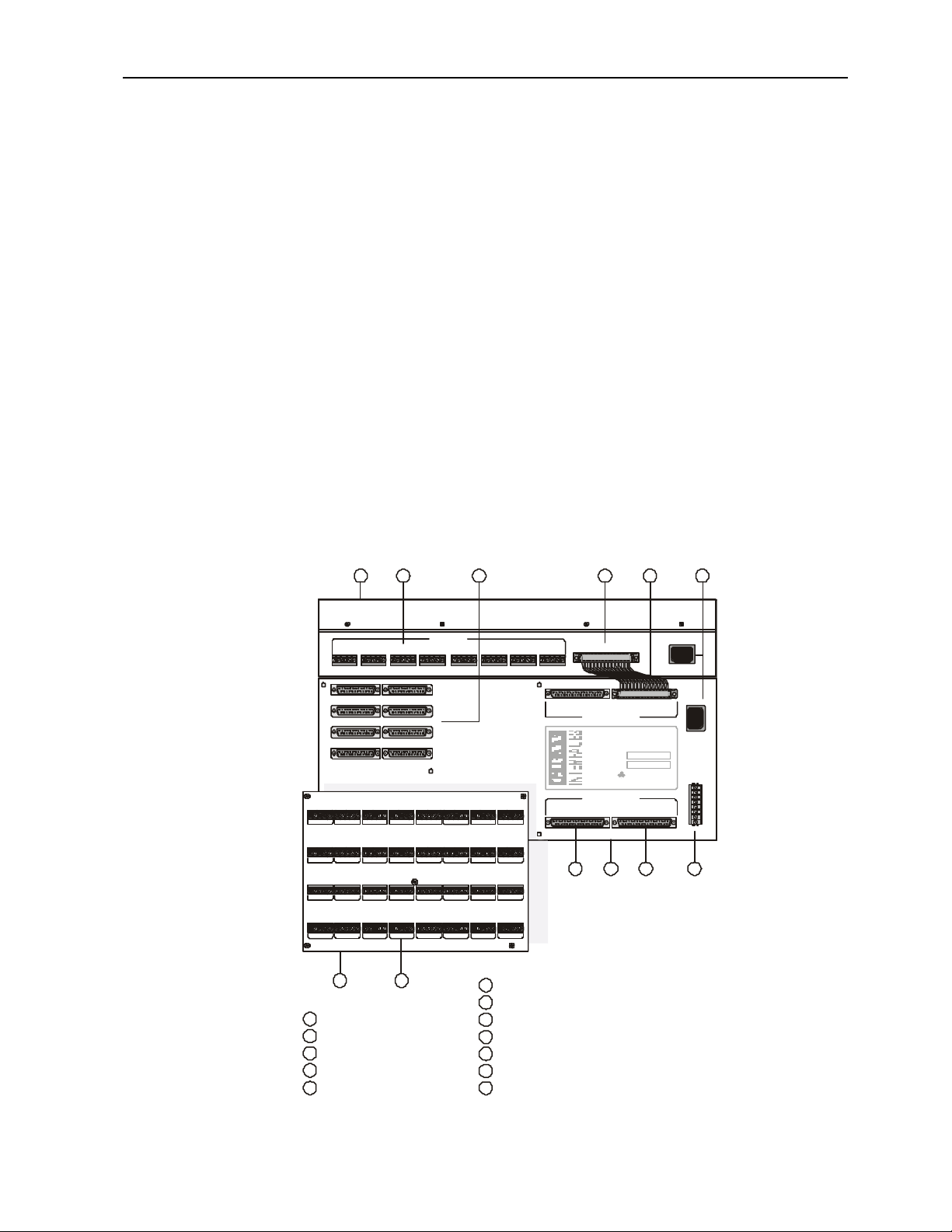
Model P2020 32-way terminal block transition boards are the most
commonly used method of connecting the DMX output station cabling. These
A
B G C D
DMX INPUTS
PORT H
1 1 1 1 1 1 1 12 2 2 2 2 2 2 23 3 3 3 3 3 3 34 4 4 4 4 4 4 45 5 5 5 5 5 5 5
J2 J1
OUTPUT 5-8 OUTPUT 1-4
J4 J3
OUTPUT 13-16 OUTPUT 9-12
J6 J5
OUTPUT 21-24 OUTPUT 17-20
J8 J7
OUTPUT 29-32 OUTPUT 25-28
TB8
TB7
TB16
TB15
TB24
TB23
TB32
TB31
PORT FPORT G
TB6
TB5
TB4
TB3
TB2
TB14
TB13
TB12
TB11
TB10
TB22
TB21
TB20
TB19
TB18
TB30
TB29
TB28
TB27
TB26
F
G
Input Module, 8-way
A
DMX Input Terminal Blocks
B
H
J
KC
Linking Cable, 37 conductor
Mains Power Supply Input
E
LD
M
E
CABLE A THRU
POWER
100-240V 50/60Hz
J9
CABLE A IN
POWER IN
100-240V
50/60Hz
PC-COM
CPS
TxD
RxD
COM
TxD+
TxDRxD+
RxD-
J11
J13
PORT APORT BPORT CPORT DPORT E
INTER-MODULE BUS
J10
CABLE B IN
INTER-MODULE BUS
DMX Pathfinder LR
32-WAY OUTPUT MODULE
MODEL NUMBER
SERIAL NUMBER
100-240 VAC
50/60Hz 1.0A
MADE IN CANADA
INTER-MODULE BUS
TB1
TB9
TB17
TB25
CABLE B THRU
J12
JMLF H K
Processor / Output Module, 32-way
DMX Output Connectors, 4-way (DB25F)
Inter-Module Bus Connector, 1-8 Inputs (DB37F)
Inter-Module Bus Connector, 9-16 Inputs
PC Communications Connection, RS232/RS485Inter-Module Bus Connection
Output Terminal Adapter Board, 32-way
DMX Output Terminal Blocks, 2 piece
5
Page 7

DMXPathfinder LR Installation & Assembly
boards mount directly to the rear of each output module using five 6-32
standoffs and screws. They electrically connect to each Output Module with
eight 25-pin D-style connectors, therefore a certain amount of force is required
to mate the two parts. Ensure that all 8 connectors are fully mated and that the
board is resting on the standoffs before installing the five screws.
If the DMXPathfinder LR is to be installed in a swing-out (hinged) type of
equipment rack, a different type of termination board is usually supplied, the
DMS-16LT type. These are 16-way boards, intended for mounting in the rear of
the equipment rack, on the rear service panel or on 4U rack panels supplied by
the installer or the factory, depending on project requirements. 25-conductor
twisted pair ribbon cables, 1-meter long, interconnect these boards with the rear
of the DMX Pathfinder LR Output Modules. Two termination boards should be
installed side-by-side on each panel. We recommend the use of 3/8"-1/2" 6-32
threaded standoffs and 1/4" screws to attach the boards to the mounting panels.
Insulated hardware is not necessary.
Using DMS-16LT termination boards, mounting and external station
cabling may be completed well in advance of installation of the rest of the
DMXPathfinder LR hardware.
I/O CABLE INSTALLATION
Input and Output cabling may enter the equipment rack through the top or
bottom. Bundle cables at either side of the rack, just in front of the termination
boards. Cabling installed to the rear of the rack from the panels will obscure
access to terminal blocks at the extreme edges of the termination boards.
Cables are then dressed into place for connection at the input/output
terminal blocks. Note the order of the terminal blocks. On 32-way boards they
are labeled TB1 to TB32 and are arranged right to left, top to bottom. On 16way boards they are labeled TB1 to TB16 and are arranged top to bottom, left
to right.
M ODULE PREPARATION
Unpack all of the DMX Pathfinder LR system modules and accessories
and arrange on a flat surface. First, locate the package of screws supplied with
6
Page 8

DMXPathfinder LR Installation & Assembly
each module, and use 8-32 screws to attach the rack mount ears to the sides of
each Input and Output Module.
If P2020 type termination boards are to be used, mate them to each
Output Module and fasten with 5 x 6-32 screws.
Using one power cord, power up each Input and Output Module one at a
time and verify that the main power LEDs illuminate.
Remove the four adhesive rubber feet from the bottom of each module.
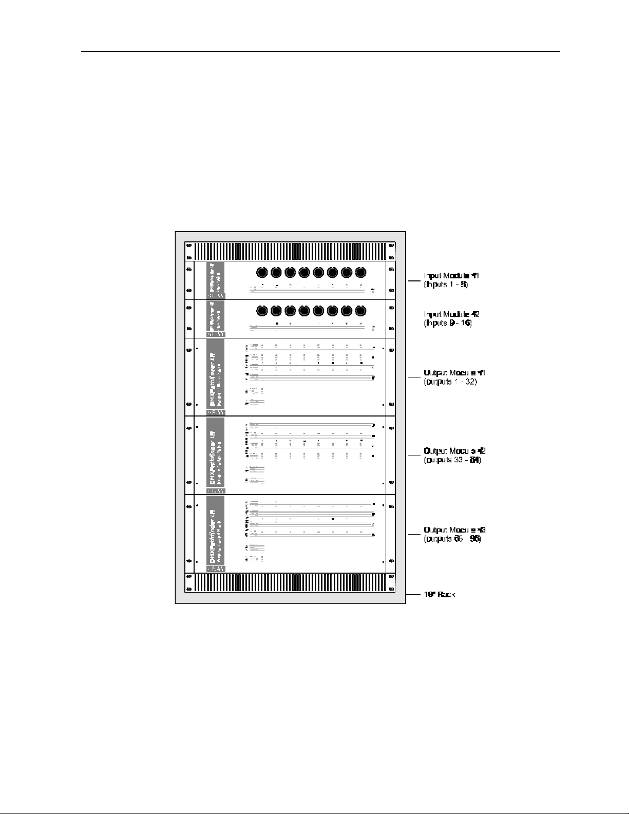
M ODULE INSTALLATION
Starting with the last (bottom) Output Module , install the modules into the
equipment rack. Normally the Input Module(s) are located above the Output
Modules, but they can both be placed at the bottom or one at the top and one at
the bottom, if desired. In any case they may not be placed between Output
Modules.
7
Page 9

DMXPathfinder LR Installation & Assembly
DMX INPUTS
PORT E
PORT F
PORT G
PORT H
111111111111111
222222222222222
333333333333333
444444444444444
555555555555555
DMX INPUTS
PORT E
PORT F
PORT G
PORT H
J2
OUTPUT 5-8
J4
OUTPUT 13-16
J6
OUTPUT 21-24
J8
OUTPUT 29-32
J2
OUTPUT 5-8
J4
OUTPUT 13-16
J6
OUTPUT 21-24
J8
OUTPUT 29-32
OUTPUT 1-4
OUTPUT 9-12
OUTPUT 17-20
OUTPUT 25-28
OUTPUT 1-4
OUTPUT 9-12
OUTPUT 17-20
OUTPUT 25-28
J1
J3
J5
J7
J1
J3
J5
J7
PORT D
PORT D
PORT C
PORT C
PORT B
PORT B
Input Module #1
(inputs 1 - 8)
Input Module #2
(inputs 9 - 16)
Output Module #1
(outputs 1 - 32)
Output Module #2
(outputs 33 - 64)
CABLE A THRU
CABLE A THRU
POWER
100-240V 50/60Hz
POWER
J9
CABLE A IN
CABLE A IN
POWER IN
100-240V
50/60Hz
PC-COM
CPS
TxD
RxD
COM
TxD+
TxDRxD+
RxD-
J11
J13
J9
POWER IN
100-240V
50/60Hz
PC-COM
CPS
TxD
RxD
COM
TxD+
TxDRxD+
RxD-
J11
J13
INTER-MODULE BUS
PORT A
PORT A
1
2
3
4
5
J10
CABLE B IN
INTER-MODULE BUS
DMX Pathfinder LR
32-WAY OUTPUT MODULE
MODEL NUMBER
SERIAL NUMBER
100-250 VAC
50/60Hz 1.0A
MADE IN CANADA
INTER-MODULE BUS
CABLE B THRU
J12
J10
CABLE B IN
INTER-MODULE BUS
DMX Pathfinder LR
32-WAY OUTPUT MODULE
MODEL NUMBER
SERIAL NUMBER
100-250 VAC
50/60Hz 1.0A
MADE IN CANADA
INTER-MODULE BUS
CABLE B THRU
J12
J9
TB8
TB7
TB6
TB5
TB4
TB3
TB2
TB16
TB15
TB14
TB13
TB12
TB11
TB10
TB24
TB23
TB22
TB21
TB20
TB19
TB18
TB32
TB31
TB30
TB29
TB28
TB27
TB26
CABLE B IN
TB1
TB9
TB17
CABLE B THRU
TB25
CABLE A IN
INTER-MODULE BUS
DMX Pathfinder LR
32-WAY OUTPUT MODULE
MODEL NUMBER
SERIAL NUMBER
100-240 VAC
50/60Hz 1.0A
MADE IN CANADA
INTER-MODULE BUS
CABLE A THRU
POWER IN
100-240V
50/60Hz
Output Module #3
PC-COM
CPS
TxD
RxD
COM
TxD+
TxDRxD+
J11
RxD-
J13
(outputs 65 - 96)
Locate the 37-conductor ribbon cable jumpers and 37-pin bus
terminator(s). There should be one 7” long cable per Input Module and one or
two 3.5” short cables per Output Module. If only one Input Module is supplied,
only one bus cable set will be used.
Attach one long jumper cable from the first Input Module to the top InterModule Bus connector marked “CABLE A IN”. Attach the other from the second
Input Module (if supplied) to the connector marked “CABLE B IN”.
Install the short ribbon cable jumpers between Output Modules. The
bottom connector marked CABLE A(B) THRU on one module connects to the
top (IN) connector on the next lower module in all cases.
Install the 37-pin bus terminator plug(s) at the bottom or last unconnected
CABLE A and B THRU jacks in the system.
8
Page 10

DMXPathfinder LR Installation & Assembly
Remember that for systems with only one input module, only the CABLE A
jacks need ribbon cable jumpers and the bus terminator installed.
I/O CABLE CONNECTION
Strip back about 3 inches (8cm) of cable jacket and braid shield from each input
or output cable. Apply a 2.5" (6.5cm) piece of 1/16" heat shrink to the drain wire
and a 1" (2.5cm) piece of 3/8" heat shrink over the exposed braid ends where
each cable was stripped. These precautions are to ensure that cable shields
cannot contact each other or equipment ground.
Strip about 1/2" of insulation from the four signal wires in each cable.
Bend over 1/4" of the exposed conductors on all five wires and connect them to
the terminal block. Note that each five-position terminal block is numbered 1
thru 5 on the termination board. This corresponds to the pin numbering on XLR
5-pin connectors, that is:
Pin 1 -- Signal Common (shield)
Pin 2 – DMX Data (-)
Pin 3 – DMX Data (+)
Pin 4 – Talkback Data (-)
Pin 5 – Talkback Data (+)
Be sure to use one twisted pair for the DMX data and the other for Talkback
data. It is also good practice to label each station cable and corresponding
terminal block header position with the cable number.
Input Modules are provided with both 5-position rear mounted terminal blocks
and parallel 5-pin XLR male faceplate jacks. In some installations, the
hardwired cable terminates at female jacks mounted on an auxiliary panel. In
this case, no connection is made to the Input Module’s rear terminal blocks;
instead short XLR patch cables are used to interconnect the auxiliary panel
jacks with the Input Module’s faceplate jacks.
9
Page 11

DMXPathfinder LR Installation & Assembly
PC-COM CABLE CONNECTION
Each Output Module is provided with an 8-position rear-mounted terminal block
for connection to the system’s personal computer. Two separate ports are
provided: an RS232 port and an RS485 port. There is also a 10VDC phantom
power supply available for powering an optional RS232/485 converter. All
connections are electrically isolated from the rest of the system, so that the PC
connection can be made without concern for ground loops or common mode
voltage problems.
Two or more PCs may be connected to a DMXPathfinder LR system
simultaneously. One can be connected to the RS232 port and another to the
RS485 port on the first Output Module, and two more to the second Output
Module, and so on. For example, say three locations are needed to connect a
PC to the system, all using RS485. If there are at least 3 Output Modules, each
of the three connections can be made at a separate module.
The following is a description of each connection from top to bottom:
CPS – Converter Power Supply, 10VDC @ 50mA
TxD – RS232 Transmit Data
RxD – RS232 Receive Data
COM – Power Supply & Signal Common
TxD+ -- RS485 Transmit Data (+)
TxD- -- RS485 Transmit Data (-)
RxD+ -- RS485 Receive Data (+)
RxD- -- RS485 Receive Data (-)
RS232/485 COMMUNICATIONS
Each system includes an RS232-RS485 converter for optional use with the
system’s Personal Computer. The maximum cable length for RS232
connections is 50 feet (15 meters). The converter is unnecessary if the PC is
less than that distance from the Pathfinder rack. Below are the connections
required for the PC’s RS232 COM port :
Pin 1 – Carrier Detect
Pin 2 – Receive Data (connect to Pathfinder “TxD” terminal)
Pin 3 – Transmit Data (connect to Pathfinder “RxD” terminal)
Pin 4 – Data Terminal Ready
10
Page 12

DMXPathfinder LR Installation & Assembly
Pin 5 – Power & Signal Common (connect to “COM” terminal)
Pin 6 – Data Set Ready
Pin 7 – Request to Send
Pin 8 – Clear to Send
Pin 9 – Ring Indicate
Only pins 2, 3 and 5 are required to connect for RS232 communications.
If the RS232/485 converter is to be used, it is strongly recommended that a 3-
pair or 4-pair RS422/485 rated twisted pair data cable is used for the
connection to the DMXPathfinder LR. Category-5 UTP cable works well. If you
are installing Cat-5 UTP, use two pairs for data and the other two for power.
The converter has 9-pin D-style connectors at both ends. One end is marked
“PC COM”, and this end will plug directly into a 9-pin male COM port on the PC.
The following is this connector’s pinout (with respect to PC COM port):
Pin 1 – Carrier Detect (Common)
Pin 2 – Receive Data
Pin 3 – Transmit Data
Pin 4 – Data Terminal Ready
Pin 5 – Signal Common
Pin 6 – Data Set Ready (Common)
Pin 7 – Request to Send
Pin 8 – Clear to Send
Pin 9 – Ring Indicate (Common)
If the converter is accidentally plugged in backwards, no damage will result. You
will have to make up an adapter cable with a 9-pin male end to connect to the
converter from the Pathfinder. The following is this connector’s pinout:
Pin 1 – Receive Data + (connect to Pathfinder “TxD+” terminal)
Pin 2 – Receive Data - (connect to Pathfinder “TxD-” terminal)
Pin 3 – No Connection
Pin 4 – Power Supply Input (+9-12VDC – connect to “CPS” terminal)
Pin 5 – Power Supply & Signal Common (connect to “COM” terminal)
Pin 6 – No Connection
Pin 7 – No Connection
Pin 8 – Transmit Data - (connect to Pathfinder “RxD-” termin al)
Pin 9 – Transmit Data + (connect to Pathfinder “RxD+” terminal)
Note that when connecting full duplex RS232 or RS485 systems, Transmit Data at one
end connects to Receive Data at the other end.
11
Page 13

DMXPathfinder LR Installation & Assembly
T ESTING THE INSTALLATION
Once all connections are made and inspected for errors, you can power up the
DMXPathfinder LR modules in the equipment rack. With no DMX source
signals present, all eight red Isolated Power LEDs on the face of each Input
Module should be illuminated. On each Output Module, the green Processor
OK and Main 5V Power LEDs should be illuminated. If, in addition, the green
Crosspoint OK LED is on, this does not indicate a problem.
At this point, refer to DMXPathfinder LR Installation and User Guide, Chapter 2
– Communications Setup to get the PC talking to the Pathfinder. Once that has
been done, go to Chapter 5 – Diagnostics and Troubleshooting and perform the
health check and loopback tests on the installation.
12
Page 14

DMXPathfinder LR Maintenance & Testing
Chapter 2: Maintenance & Testing
CARD REPLACEMENT
Should a defective component be found in an Output Module or other
module during troubleshooting, it is best to replace the suspected defective
circuit card with a spare unit and re-test. Powering down the entire
DMXPathfinder, or at least the specific module, is recommended before
removing or inserting cards.
To replace an Output Module card, first remove loosen the four front panel
Phillips screws and the panel, then grasp the card stiffener bracket (or ejector
handles), and pull the card straight out of the module chassis. Carefully align the
replacement circuit board into the chassis' left and right card guides and slide
the unit in until it protrudes about 5mm, then push the module firmly into its
mating backplane receptacles. The card is not fully seated unless its front edge
is flush with the front of the metal chassis.
If the CPU card was replaced, check that the rotary and DIP switches have
been set the same as the replaced card.
Before replacing the front cover, first restore power and depress the
RESET pushbutton on the first Input Module until the system resets (Processor
OK LED goes out). Then re-test the system to ensure that the fault has been
corrected. If the entire rack was powered off, it is unnecessary to press RESET
since a system-wide reset cycle always occurs automatically on power-up.
If you forget to press the RESET pushbutton after module replacement, the
function can be initiated from the DMXQConnect program at the personal
computer.
T EST PROCEDURES
System testing by maintenance personnel will usually be carried out in
response to a fault that has developed somewhere in the system. Powerful
diagnostic instruments are available to assist maintenance technicians with this
task: the Fluke Model 650 LAN Cable Meter, and Goddard Design Li'l DMX'ter,
amongst others. These will be described in more detail below. In general,
though, the procedures outlined in Chapter 5 and the troubleshooting
instructions in this Chapter are likely to help solve the vast majority of problems
encountered, especially where any system downtime cannot be tolerated.
13
Page 15

DMXPathfinder LR Maintenance & Testing
Tests using instrumentation will be performed where anomalies have
developed in the system that cannot be isolated with standard troubleshooting
procedures. Additionally, testing can establish minimum network performance
where non-DMX512 control equipment is to be connected to the system.
Fluke 650 Cable Meter -- Please refer to the manufacturer's user's
manual for detailed instructions and theory before attempting to use this
instrument. It’s not obvious to the first time user! The Fluke 650 is provided with
a battery-powered remote plug-in unit, a set of 2 adapter cables (RJ45 to 5-pin
XLR) and an AC adapter. The unit may be powered by a 9-volt alkaline battery,
but battery life tends to be rather short with the 650 so use of the AC adapter is
recommended.
When the remote unit is connected to the other end of any DMX cable run,
the 650 will verify wiring continuity on all pins except ground (pin 1). Cable
length can also be measured with the instrument, and any anomalies, e.g.
changes in line impedance will be detected. The 650 measures performance of
the cable installation at up to 10 million bits per second.
The Fluke 650's signalling is not compatible with the DMX Pathfinder LR
electronics or any other DMX generating or receiving equipment. Thus its
usage should be confined to the cable installation only.
Goddard Design Li'l DMX'ter -- This useful instrument can test most
aspects of the DMX Distribution System, from wiring continuity to signal
propagation through the Pathfinder electronics. Since the DMX'ter can both
generate and receive DMX512, it is 100% compatible with all aspects of the
distribution system, including any control system or receiving device. The
DMX'ter will directly control any receiving unit, and will verify the output of a
controller by displaying the data on an LCD readout. In addition, the instrument
will test cable continuity on all five XLR pins. Please refer to the Li'l DMX'ter
Operating Manual for more information.
Other Test Equipment -- The maintenance technician will find the
following additional test equipment useful:
.1 Oscilloscope -- for viewing data in conjunction with the
DMX'ter and its scope trigger module; for checking that both differential signals
are present on a given data line; for evaluating the performance of crosspoint
matrix and opto-repeater circuitry at higher operating speeds (greater than 250
Kbits per second).
14
Page 16

DMXPathfinder LR Maintenance & Testing
.2 Frequency Generator -- for testing crosspoint matrix and
opto-repeater high-speed performance. Useful for evaluating whether other
systems with higher data rates can be used in the network.
.3 Digital Volt/Ohm Meter -- a general purpose tool for
checking continuity, termination resistor values and power supplies.
ADVANCED T ROUBLESHOOTING
As described earlier, basic troubleshooting usually involves isolating a
troublesome or defective opto-repeater circuit, card or module and replacing it
with a known good one. It may also include checking for obvious things such as
incorrect addressing or DMX protocol incompatibility with DMX receiving
devices, absence of a line terminator, defective DMX patch cables, or even
incorrect control console configuration.
Once all basic troubleshooting checks have been completed, without the
desired resolution of the problem, more sophisticated faultfinding may be
carried out. It is recommended to use a portable computer connected to the
RS232 PC-COM port on one of the Output Module s so that test patching and
diagnostics can be done right at the DMX Pathfinder itself. First, however, try
swapping input or output cable connections on the back of the Pathfinder
modules with adjacent ones to use a different receiver and transmitter circuits.
Next, a DMX tester should be used to either transmit DMX in place of the control
console, or receive DMX in place of the receiving device(s). Check the
receiving device by connecting the DMX tester directly to it in transmit mode.
Then set the tester to receive mode and monitor the data coming to the
Pathfinder from the console, by plugging into the Input Module faceplate XLR
with a female-female cable. If this test does not point to the data source or the
receiving device as being the cause of the problem, there may be a slight
incompatibility between them as far as DMX512 is concerned. However, if the
two units had previously worked together, these tests will point to a problem in
the DMX cable installation or in one of the DMXPathfinder modules.
At this point, the suspect Output Module’s output card or should be
withdrawn from its chassis and the spare unit inserted in its place (remember to
power down before withdrawing or inserting any cards). If this proves that the
original unit is defective, inspect the card for signs of damage or any other
obvious cause. Return the defective card to the factory for repair unless you
have the facilities to carry out your own service. For more serious defects, such
as power supply or fan failure, disconnect the entire module and take it to the
test bench for repair, or return it to the factory. DMXPathfinder LR modules are
not difficult to service with basic tools and test equipment. If the suspect module
15
Page 17

DMXPathfinder LR Maintenance & Testing
proves to be good, test the DMX cable installation for open or shorted lines
using the DMX QConnect loopback test diagnostic (see Chapter 5). A similar
test can be done for input cabling.
If the above tests yield passing results and the problem persists, it may be
necessary to use the Fluke LAN Cable Meter to do a high-frequency analysis of
the suspect cable runs. This test will quickly indicate any anomalies having to
do with cable impedance and capacitance that would result in excessive signal
distortion or attenuation. This test will help to locate less-obvious problems such
as pinched or over-heated cabling that cannot be found with simple continuity
checks.
DMXPathfinder LR Installation and User Guide, Chapter 5 covers the
easy to use diagnostic features of the DMXQConnect software. The
diagnostics can be used to check for defective Pathfinder internal hardware and
to carry out system maintenance procedures such as cable and termination
integrity checks. Please take the time to familiarize yourself with the capabilities
of these diagnostics as they have the potential for helping to save a great deal
of effort and system downtime.
SYSTEM RESET
Under normal conditions, the user never needs to interact with any part of
the DMXPathfinder LR module installation. Exceptions to this might include
checking the LED status as described previously, or having to recover from a
temporary component failure or when service and card replacement is being
carried out.
A “System Reset” pushbutton has been provided on the face of each Input
Module for the latter purpose. It’s important to remember that only the reset
button on the first Input Module is active. If you depress either one, however, you
will assume that both are inactive as nothing will happen. You will need to
depress and hold the correct one for at least two seconds to initiate a reset
cycle. The external reset function was designed this way to help prevent anyone
from accidentally resetting the DMX Pathfinder and momentarily interrupting the
flow of DMX data through it.
16
Page 18

DMXPathfinder LR Index
INDEX
9
9-pin D-style connectors · 10
A
Advanced Troubleshooting · 14
Ambient temperature · 3
Assembly · 3
B
bus terminator · 8
C
CABLE A IN · 8
CABLE A(B) THRU · 8
CABLE B IN · 8
cabling · 6
Card Replacement · 12
Cat-5 UTP cable · 10
COM · 10
COM port · 10
control console · 14
Cooling · 3
CPS · 10
CPU · 12
Crosspoint OK LED · 11
D
diagnostic instruments · 12
diagnostics · 14
Digital Volt/Ohm Meter · 14
DIP switches · 12
DMS-16LT · 6
DMX · 2, 11
DMX Data · 9
DMX distribution system · 13
DMX'ter · 13
E
Environmental Considerations
· 3
equipment rack · 3, 4, 6, 7, 11
F
Fan · 3
Frequency Generator · 14
G
Goddard Design · 13
ground loops · 10
H
humidity · 3
I
I/O Cable Connection · 9
I/O Cable Installation · 6
Input Module · 5, 7, 11
Installation · 3
installer · 4
Inter-Module Bus connector · 8
Isolated Power LED · 11
L
LAN Cable Meter · 12, 13, 15
LED status · 15
Li'l DMX'ter · 12, 13
Loopback Test · 15
M
Main 5V Power LED · 11
Module Installation · 7
Module Preparation · 6
O
opto-repeater · 14
Oscilloscope · 13
output card · 14
Output Module · 5, 6, 7, 9, 10,
11, 12, 14
P
P2020 · 5, 7
PC COM · 10
PC-COM Cable Connection · 9
PC-COM port · 14
personal computer · 9, 10
pinout · 10
Power Requirements · 4
Processor OK LED · 11, 12
R
Rack Placement · 4
Rack Sizing · 4
Relative humidity · 3
RESET · 12
ribbon cable · 6, 8
RS232 · 9, 14
RS232/485 converter · 10
RS485 · 9
rubber feet · 7
RxD · 10
S
Signal common · 9
System Reset · 15
System testing · 12
T
Talkback · 9
temperature · 3
terminal block · 5, 6, 9
termination boards · 3, 5
Test Procedures · 12
TESTING · 12
Testing the Installation · 11
transition boards · 5
troubleshooting · 12, 14
TxD · 10
U
UTP cable · 10
17
Page 19

DMXPathfinder LR Index
V
vent · 4
X
XLR · 9, 14
18
 Loading...