

Page 1
LCRD16 RELAY DRIVER
7.2500"
0.2500"
0.5000"
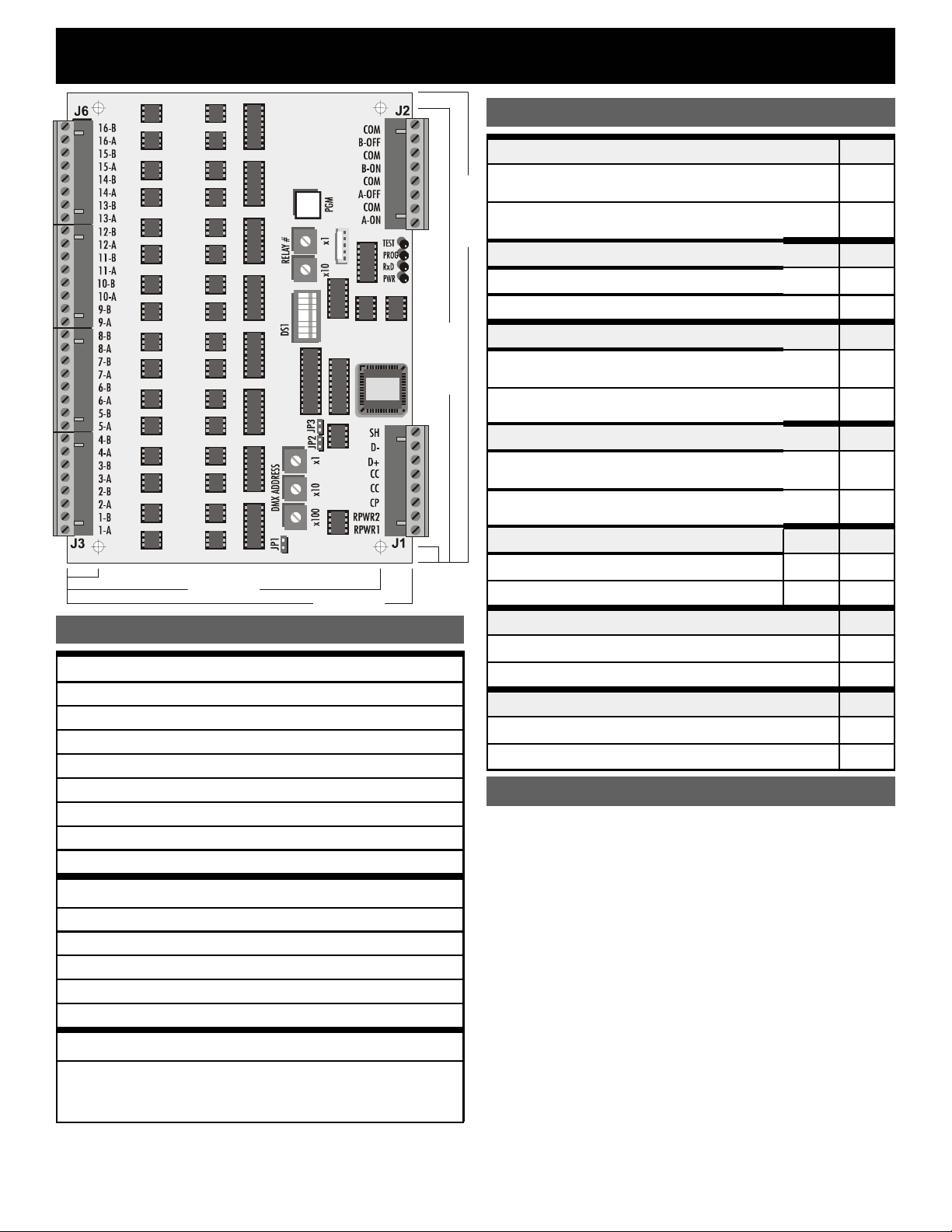
CONNECTOR LEGEND
RPWR1
RPRW2
CP
CC
CC
D+
DSH
CONNECTOR J2
A-ON
A-OFF
B-ON
B-OFF
COM
CONNECTOR J3-J6
1A/B
thru
16A/B
NOTE: Relay coil drive maximum rating 300mA continuous, 3A
surge (inrush). Use a pilot relay for higher current requirements.
CONNECTOR J1
Relay Coil Power Supply (Hot), 24VAC
Relay Coil Power Supply (Neut.), 24VAC
Control Power Supply 12-24VAC or DC(+) 200mA
Control power supply common
Control power supply common
DMX512 Data +
DMX512 Data DMX512 Shield
Master Switch “A“ input, momentary ON
Master Switch “A” input, momentary OFF
Master Switch “B” input, momentary ON
Master Switch “B” input, momentary OFF
Master Swit c h common (4 positions)
Relay coil drive outputs, one coil drive wire each for
momentary polarized pulse-latchi ng relays and AC
maintained coil relays (“A” lead); one coil common
wire per relay (“B” lead)
5.0000"
5.5000"
PROGRAMMABLE WITH
MASTER SWITCH INPUTS
Configuration
DIP Switch Settings
RELAY TYPE DS-1
Momentary: Outputs a 100ms polarized DC pulse
for 2-wire latching relays
Maintained: Outputs a constant AC voltage for
7.5000"
maintained relays
THRESHOLD SELECT
25% Threshold (on at 30%, off at 20%)
75% Threshold (on at 80%, off at 70%)
DS-2
OFF
OUTPUT SCAN MODE DS-3
Scan Mode Enabled:
Turns relays on or off in sequence, 10 per second
Scan Mode Disabled:
Turns relays on or off simultaneously
CONTROL MODE
Patch:
Addressing determined by user programmed patch
Offset:
Addressing determined by address select switches
PROGRAM MASTER SWITCH
Program Master Switch “A”
Program Master Switch “B” OFF ON
PROGRAM MODE
Program Mode Enabled
Program Mode Disabled
ON
DS-5 DS-6
ON OFF
TEST MODE DS-8
Test Mode enabled
Normal (Run) Mode
TEST MODE
DS-7 must be OFF and DS-8 ON. The “TEST” LED will
be on.
Relay Test Function: DS-4 must be off. The DMX
address switches select the relay number to test. The
selected relay can then be turned on by pressing the
program pushbutton. If the number is out of the correct
range (000 to 016 in mom entary mode) the "TEST" LED
will flash to indicate an error when the button is pressed.
DMX Test Function: The DMX receive LED (RxD) will
be on and steady if a valid DMX signal is received. If no
DMX signal is present the LED will be off. If the DMX
signal is not valid the LED will flash continuously.
Patch Testing Mode: DS-4 must be on. The address
switches select the DMX channel #. When the program
pushbutton is pressed, relays assigned to that DMX
channel # will turn ON. When the pushbutton is released
those relays will turn OFF. The "TEST" LED will flash
once if there is an error in the address range selection.
ON
OFF
ON
OFF
DS-4
ON
OFF
DS-7
ON
OFF
ON
OFF
Page 2

LCRD16 RELAY DRIVER PAGE 2 OF 2
PROGRAMMING
The “PROG” LED is on when Program Mode is enabled.
Program Patch: DS-5 OFF, DS-6 OFF, JP1 open
The address switches set the equivalent DMX channel #
(001 to 512) and the relay switches select the output
number (01 to 16). Pressing the program store
pushbutton (S6) to store the patch assignment will ca use
the program (PROG) LED to flash once unless an
incorrect DMX # or relay # has been selected.
NOTE: Address 000 is used to clear the patch
assignment for the selected relay. Each relay can be
assigned to only one DMX channel. A new assignment for
an relay overwrites the previous assignment for that relay.
Clear Patch:
The entire patch will be cleared when the program
pushbutton is pressed. The "PROG" LED will flash once
to indicate a successful execution.
Program Master Sw.A:
The RELAY# switches select the device number to
connect. The program (PGM) pushbutton is pressed to
execute. The “PROG” LED will flash once unless an
incorrect relay number has been selected. The “TEST”
LED will illuminate to indicate that the selected relay has
been assigned to the switch input. Repeat this procedure
to add additional relays to this switch.
Program Master Sw.B:
Follow the same procedure as above for Master Switch A.
Verify: To check the connection between a master
switch and an assigned relay, set the RELAY# switches
to the desired relay and the connect status will be
indicated by the "TEST" LED (ON if connected, OFF if not
connected). To set or clear the connection, simply toggle
the program button. Each master switch can be
connected to any combination of valid relays. Master
switches can only be tested while in the program mode.
Clear Master Sw.A:
Press the program pushbutton to clear all relay
connections to master switch A. The "PGM" LED will flash
once.
Clear Master Sw.B:
Press the program pushbutton to clear all relay
connections to master switch B. The "PGM" LED will flash
once.
DS-5 OFF, DS-6 OFF, JP1 shorted
DS-5 ON, DS-6 OFF, JP1 open
DS-5 OFF, DS-6 ON, JP1 open
DS-5 ON, DS-6 OFF, JP1 shorted
DS-5 OFF, DS-6 ON, JP1 shorted
SUPPORT
Technical support is available from Pathway Connectivity
at +1 (403) 243-8110, Monday to Frida y, from 9 a.m. t o 5
p.m. Mountain time. Please have the un it model number
and serial number ready when you call. If you need to
return anything for any reason, contact the factory in
advance for return instructions.
NOTES ON CONTROL MODE
Patch Mode Operation: Addressing is determined
by the programmed DMX patch assignment for each
relay. In this mode, any relay can be assigned to any
DMX channel # in any order. Any number of relays can be
assigned to the same DMX channel, but each relay can
be assigned to only one DMX channel.
Offset Mode: The card's start address is determined by
the DMX address select switches (S1-S3). These
switches select the DMX address for the first relay and all
other relays controlled by the card follow in sequence.
NOTES ON DMX OPERATION
When a DMX signal is used to control relays, on or off
operation occurs as signal levels pass through the
threshold set. If the DMX signal fails while relays are in
the ON state, those relays will turn off after a two minute
timeout unless they were previously turned on by a
NOTES ON MASTER SWITCHES
Master switch inputs function in a "highest level takes
precedence" (HTP) mode of operation with the DMX
signal. If the DMX level for a given relay is above the set
threshold, the master switch will not turn that relay off.
Similarly, lowering the DMX signal for a relay will not turn
that relay off if a master switch has previously turned it
on. This function allows the user to pre-set relays to the
ON state prior to lowerin g or shutting off the DMX signal .
In the absence of a DMX signal, the A and B master
switches will operate in a "last action takes
precedence" (LTP) mode, that is, either one will turn on or
off a relay assigned to both switches.
DMX TERMINATION JUMPERS
DMX data lines must always be terminated with the
proper resistance at the last receiving device on each
line. Install the JP2 and JP3 shorting jumpers if the card is
at the end of the DMX line, otherwise leave the jumpers in
the default (open) position.
RUN (NORMAL) MODE CHECKLIST
• JP1 is removed
• DS-1 set for correct relay type
• DS-2 set for relay operating threshold
• DS-3 set for scan or simultaneous relay operation
• DS-4 set for patch or offset address mode
• DS-5 and DS-6 (program select) turned off
• DS-7 (program mode) and DS-8 (test mode) are off
• JP2 and JP3 (DMX Terminate) installed or removed
as required
rev5 ver1.0
Pathway Connectivity Inc ., 480C - 36 Avenue S.E.,
Calgary, AB, T2G 1W4 Canada
support@pathwayconnect.com
www.pathwayconnect.com
tel (403) 243-8110 fax (403) 287-1281
2
Printed in Canada
09/03
 Loading...