

Page 1
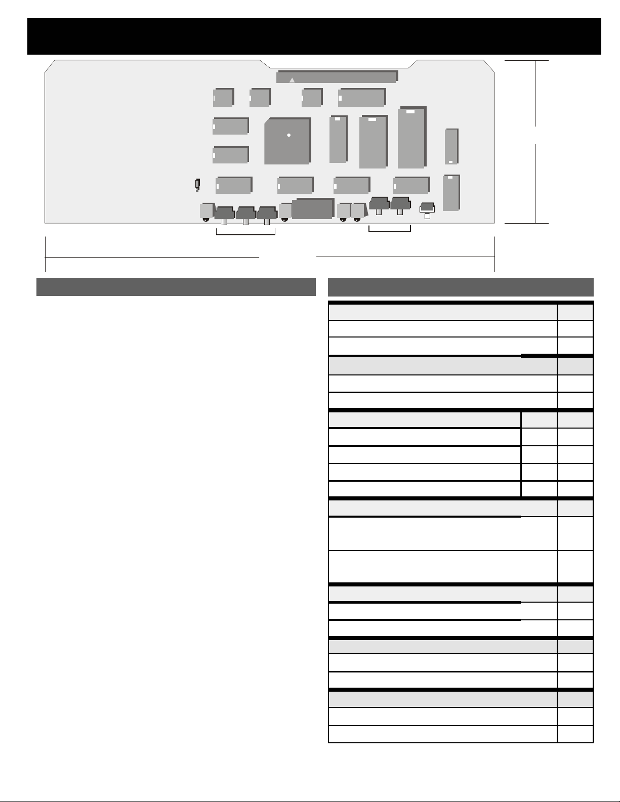
LCRC48GEP DMX RELAYCONTROLLER Configuration
J1
3.7"
OPEN POSITI ON SHOWN
JP1
x100 x10 x1
RxD
ADD RESS SELECT
INSTALLATION INSTRUCTIONS
Ensure that relay panel power is off (no indicator LEDs
1 -
glowing on the system motherboard). Remove the metal
cardframe cover.
Connect the DMX data line at the panel motherboard, with D-
2 -
to the black terminal and D+ to the red terminal. Attach the
shield drain wire to the SHIELD terminal.
If the DMX line is to be passed through to another panel,
3 -
attach the outgoing wires to the second set of data terminals.
If the relay panel is the last panel on the DMX wire run, it is
4 -
recommended that a 100 or 120 ohm 1/4W termination
resistor be installed between one pair of black and red data
line terminals.
Connect switch wiring to the A/B master switch input terminals
5 -
as required. The white terminal is switch common, the red is
switch "on", and black is switch "off". Conn ect the pilot lamp t o
the yellow terminal adjacent to the first of the assigned relays.
Plug the controller card and one to four LCRD-12 driver cards
6 -
firmly into the cardframe.
Configure the controller card according to the following DIP
7 -
switch settings. Restore power.
Check that the power LED (between the DIP switch and t he
8 -
three rotary switches) is glowing steadily. This indicates +5
volts present and correct microprocessor operation . A flashing
LED indicates a defective controller card.
Follow the program mode instructions to program the card for
9 -
optional DMX patch assignment and panel master switch
inputs.
Apply the DMX control signal and observe that the receive
10-
data LED (at left) is glowing. The LED will not glow if the
address set on the rotary switches exceeds eit her 512 or the
number of dimmer signals present on the data line, if the data
format does not conform to USITT-DMX512, or if the data
wires are reversed at the mother board.
Verify relay operation with the DMX control system or the
11-
card's test function, then use the checklist to ensure that
everything is set correctly before re-installing the cardframe
cover.
PWR
10.3"
ON= DOWN
DS
x1
PGM TST
x10
RELAY SELECT PROG RAM
S1
DIP Switch Settings
THRESHOLD SELECT DS-1
25% THRESHOLD (Trigger on at 30%, off at 20%) ON
75% THRESHOLD (Trigger on at 80%, off at 70%)
STATUS QUO
ON (INFINITE HOLD) ON
OFF (2 SECOND HOLD) OFF
RELAY SELECTION DS-3 DS-4
1-12 RELAYS INSTALLED
13-24 RELAYS INSTALLED
25-36 RELAYS INSTALLED ON OFF
37-48 RELAYS INSTALLED OFF OFF
ON ON
OFF ON
CONTROL MODE DS-5
PATCH
Addressing determined by programmed patch for
each relay
OFFSET
Panel start address determined by the address
select switches
SCAN RATE
FAST SCAN (50 msec., 20 relays per second)
NORMAL SCAN (100 mseC., 10 relays per second)
PROGRAM MODE
Program Mode Enabled
Program Mode Disabled (RUN MODE)
TEST MODE DS-8
Test Mode enabled
Normal (RUN) Mode
OFF
DS-2
ON
OFF
DS-6
ON
OFF
DS-7
ON
OFF
ON
OFF
Page 2
LCRC-48GEP DMX RELAY CONTROLLER Configuration
NORMAL (RUN) MODE CHECKLIST
1- JP1 is in the "open position"
2- DS-1 and DS-2 set for relay operating threshold
3- DS-3 and DS-4 set for number of rel ays in panel
4- DS-5 set for patch or offset mode
5- DS-6 set for normal or fast rel ay scan rate
6- DS-7 (program mode) and DS-8 (test mode) are off
PROGRAMMING
DS-8 must be off and DS-7 on. The “PGM” LED will be on.
Program Patch: DS-5 ON, JP1 OPEN
The address switches set the equivalent DMX device
channel (001 to 512) and the relay switches select the
relay number (01 to 48). Pressing the program store
pushbutton (S1) to store the patch assignment will caus e
program (PGM) LED to flash once unless an incorrect
address or relay value has been selected.
NOTE: Address 000 is used to clear the patch
assignment for the selected relay. Each relay can be
assigned to only one DMX channel. A new assignment for
a relay overwrites the previous assignment for that relay.
Clear Patch:
DS-5 ON, JP1 SHORTED
The entire patch will be cleared when the program
pushbutton is pressed. The "PGM" LED will flash once to
indicate a successful execution.
Program Master Sw.A: DS-5 OFF, DS-6 OFF, JP1 OPEN
The relay switches select the relay number to connect.
The program pushbutton is pressed to execute. The
“PGM” LED will flash once unless an incorrect relay value
has been selected.
Program Master Sw.B:
DS-5 OFF, DS-6 ON, JP1 OPEN
The relay switches select the relay to connect. The
program pushbutton is pressed to execute. The “PGM”
LED
will flash unless an incorrect relay value has been
selected.
NOTE: To program a Master Swit ch the DMX address
switches must be set to an address other than 000. To
clear the connection between a master switch and an
assigned relay, set the address select switches to 000
and press the program button. Each master switch can be
connected to any combination of valid relays. Panel
master switches can be tested while in the program
mode.
Clear Master Sw.A:
DS-5 OFF, DS-6 OFF, JP1 SHORTED
Press the program pushbutton to clear all relay
connections to master switch A. The "PGM" LED will flash
once.
NOTES ON GROUNDING
Pay particular attention to the grounding of the data line shield.
If the DMX controller grounds the shield, that is sufficient. If not,
a jumper wire must be installed between the data li ne SHIELD
terminal and the relay panel COM terminal. Only one such
ground connection should be made in any one data cable run.
TEST MODE
DS-7 must be off and DS -8 on. T he “T ST ” LE D will be on.
DS-5 ON...PATCH TES TING MODE
The address switches select the DMX device channel. When
the program pushbutton is pressed the assigned relay(s) and
their status LEDs will turn on. The "TST" LED will flash once if
there is an error in address range selection.
DS-5 OFF...RELAY AND DMX TEST FUNCTION
The address switches select the relay number to test. The
selected relay can then be turned on by pressing the program
pushbutton. If the number is out of the correct range (000 to
048) the "TST" LED will flash to indicate an error when the
button is pr essed.
The DMX receive LED (RxD) will be on and steady if a valid
DMX signal is received. If no DMX signal is present the LED
will be off, and if the DMX signal is not valid the LED will flash
continuously.
NOTES ON DMX OPERATION
When a DMX signal is used to control relays, on or off operation
occurs as signal levels pass t hrough the set threshold. If the DMX
signal fails while relays are in the on state, those relays will turn off
after a two second timeout unless STATUS QUO was turned ON or
they were turned on by a panel master switch (see below)
NOTES ON CONTROL MODE
PATCH MODE OPERATION: Addressing is determined by the
programmed DMX patch assignment for each relay. In this mode,
any relay can be assigned to any DMX device in any order. Any
number of relays can be assigned to the same DMX channel, but
each relay can be assigned to only one DMX channe l
OFFSET MODE: Panel start address is determi ned by the address
select switches. These switches select the DMX address for relay
#1 and all other relays in that panel follow sequentially.
NOTES ON PANEL MASTER SWITCHES
Panel master switch inputs function in a "highest level takes
precedence" (HTP) mode of operation with the DMX signal. If the
DMX level for a given relay is above the set threshold, the panel
master switch will not turn that relay off. Similarly, lowering the DMX
signal for a relay will not turn that relay off if a master switch has
previously turned it on. This function allows the user to pre-set
relays to the on state prior to lowering or shutting off the DMX
signal. In the absence of a DMX signal, the A and B master
switches will operate in a "last action takes precedence" (LTP)
mode, that is, either one will turn on or off a relay assigned to both
switches.
Panel master switch inputs ma y be operated by either momentary
of maintained action switches or contacts. If a momentar y switch is
used, connect as per step #3 in the installation instructions. For
maintained switches, connect the RED (ON) and BLACK (OFF)
terminals together, then connect those to one terminal of the switch.
The other switch terminal connects to WHITE (SWITCH
COMMON). When the maintained contact closes, assigned relays
will be cycled ON, when the contact opens assigned relays will
cycle OFF.
The ON cycle will also occur if the switch contact is in t he closed
rev.4 ve r. 4.2 release 1
Pathway Connectivity Inc., 480C - 36 Avenue S.E.,
Calgary, AB, T2G 1W4 Canada
support@pathwayconnect.com
www.pathwayconnect.com
tel (403) 243-8110 fax (403) 287-1281
Printed in Canada
05/03
 Loading...