

Page 1
LCPM PROTOCOL MANAGER Configuration
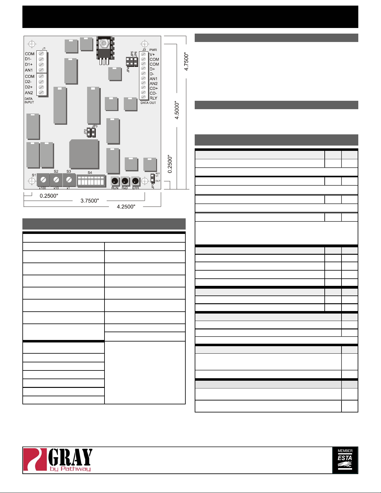
LED INDICATORS
Three LEDs are used to indicate power supply and processor run status and data
receive detection.
Glowing steadily indicates power supply and processor OK; off indicates no
RUN
power, and flashing indicates defective proces sor hardware.
Glowing steadily indicates data 1 signal received; off indicates no signal
RxD
present. Note that an address selection out of the range of the data signal
will extinguish the LED.
Glowing steadily indicates data 2 signal received; off indicates no signal
ERR
present. Note that an address selection out of the range of the data signal
will extinguish the LED.
ADDRESS SELECTION
Three rotary switches select the offset start address for the unit in most
configurations. For dual AMX output, the address switches select the starting
dimmer number for the second AMX output line. In test mode, the switches set
dimmers to full one at a time. The switches are set as (S1) hundreds, (S2) tens
DIP SWITCH SETTINGS
OPERATING MODE 1 2
ON ON
OFF ON
ON OFF
OFF OFF
OFF
7
5
ON
OFF
6
ON
8
ON
CONNECTOR LEGEND
CONNECTOR J1 CONNECTOR J3
INPUT SIGNAL COMMON
COM
DMX1 DATA- / AMX1 CLOCK-
D1-
INPUT
DMX1 DATA+ / AM X1
D1+
CLOCK+ INPUT
AMX1 ANALOG INPUT
AN1
INPUT SIGNAL COMMON
COM
DMX2 DATA- / AMX2 CLOCK-
D2-
INPUT
DMX2 DATA+ / AM X2
D2+
CLOCK+ INPUT
AMX2 ANALOG INPUT
AN2
JUMPERS
FACTORY USE
JP1
FACTORY OPTION USE
JP2-3
Shunt for DMX OUTPUT
JP4-5
Open for AMX OUTPUT
Open for AMX1 OUTPUT
JP6
RELAY DRIVE OUTPUT
JP7
+9 to +12VDC @150mA
V+
POWER SUPPLY COMMON
COM
OUTPUT SIGNAL COMMON
COM
DMX DATA+ / AM X1 CL O CK +
D+
OUTPUT
DMX DATA- / AMX1 CLOCK-
D-
OUTPUT
AMX1 ANALOG OUTPUT
AN1
AMX2 ANALOG OUTPUT
AN2
AMX2 CLOCK+ OUTPUT
CD+
AMX2 CLOCK- OUTPUT
CD-
RELAY DRIVE OUTPUT
RLY
Open collector output used with
V+ to drive external relays/
LEDs
BACKUP
Input 1 takes priority over 2: input 2 is activ e on loss of 1
PILE-ON
Highest channel on each input takes precedence
MERGE
Input 2 appended to input 1 for one continuous output stream
TEST MODES (de termined by I/O mode)
Input Test: Receive data LEDs indicate correct data signal (on steadily), faulty or
incorrect signal (flashing), or absence of any signal (off).
Output Test: Desired output protocol transmitted on dimmer selected by Address
Switches. Output set to full or cycled per switch 8.
I/O MODE 3 4
DMX INPUT – DMX OU TPUT ON ON
DMX INPUT – AMX OUTPUT OFF ON
AMX INPUT – AMX OUTP UT ON OFF
AMX INPUT – DMX OUTPUT OFF OFF
DUAL AMX OUTPUT (Functional only in pile-on or backup modes)
DUAL AMX OUTPUT ENABLED ON
DUAL AMX OUTPUT DISABLED OFF
STATUS QUO HOLD TIME
ENABLED (5 MIN. TIME OUT)
DISABLED (2 SEC. TIMEOUT)
Maintains last dimmer settings for a set time on loss of input data signal
CALIBRATE M ODE
D/A OUTPUT ENABLED
Analog output level can be tested at J3-AN1 using a DC voltmeter: no other functions
active
D/A OUTPUT CHECK DISABLED OFF
TEST CYCLE MODE
TEST CYCLE ENABLED
Ramps the selected dimmer up and down continuously between zero and full
TEST CYCLE DISABLED
Sets the selected dimmer to full
rev8 ver3.0
Pathway Connectivity Inc., 480C - 36 Avenue S.E.,
Calgary, AB, T2G 1W4 Canada
support@pathwayconnect.com
www.pathwayconnect.com
tel (403) 243-8110 fax (403) 287-1281
Printed in Canada
09/03
 Loading...