

Page 1
Model 1006 24-Channel
TM
DMX IN FROM
MENU FUNCTION
Analog to DMX
OVERVIEW
The 1006 Analog to DMX interface provides the ability to
convert analog 0-10VDC signals to DMX512 protocol. The
analog inputs may also be used as dry contact inputs, either
triggering a DMX channel to full, or to recall up to 24 presets.
The DMX input may be merged with the analog input signal or
with the preset recall. The DIN form factor makes installation
in your own enclosures or cabinets fast and easy.
The module is RDM discoverable and congurable.
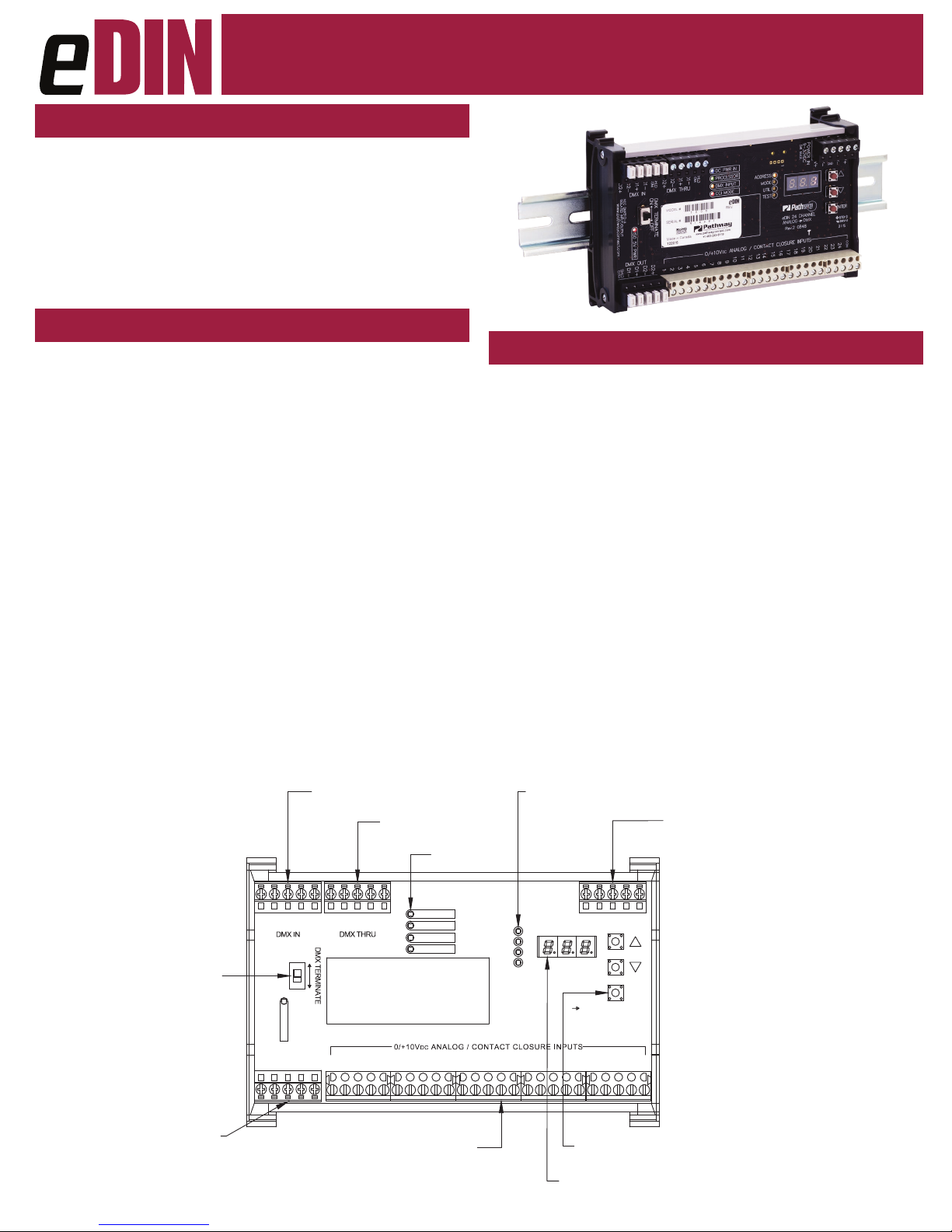
CONNECTIONS
The 1006 features terminal strips that can be removed from the
card to facilitate easy wiring installation or replacement. Make the
following connections, WITH THE POWER TURNED OFF.
POWER
The module will run on a range from 9 to 30 VDC at a maximum
of 5 Watts. Observe the correct polarity when connecting the V+
and V-. A second set of terminals are provided on the connector to
daisy-chain power to other eDIN modules. The EARTH GROUND
terminal must be connected to the enclosure’s chassis or electrical
ground terminal to ensure EMC compliance.
DMX512
DMX connections consist of a shield and data pair. Connect the
DATA+ and DATA- wires to D1+ and D1- respectively for each of
DMX IN, DMX OUT and DMX THRU (if applicable). Observe the
same polarity convention throughout the system. Connect the cable
shield to the SHLD COM terminal.
DMX OUT is the processed output of the interface. DMX IN is
optional; DMX input will be merged with the analog inputs or used
as a source of levels when recording presets.
DMX THRU may be daisy-chained to the DMX IN of other eDIN
modules.
Manual
STATUS INDICATORS
POWER IN Blue. Steady glow indicates power supply OK;
o indicates no power.
PROCESSOR Green. Steady glow indicates processor is OK;
o when POWER IN is lit indicates processor
failure.
DMX INPUT Amber. Steady glow indicates port latched
to active DMX source; o indicates no signal
present.
CCI MODE Red. Steady glow indicates contact closure input
mode is active.
FUNCTION Amber. Indicates the function associated with
the numeric display.
ANALOG / CONTACT CLOSURE INPUTS
The 1006 supports 24 discrete inputs that can be congured as
either analog or contact closure inputs. The COM (common) terminal
must be used as a signal reference, regardless of input conguration.
Analog inputs must be 0 to +10 VDC with respect to COM. Contact
inputs are simply maintained or momentary dry contact closures
between COM and the individual input.
ADDRESS
MODE
UTIL
TEST
13
14
LEDs
eDIN 24 CHANNEL
ANALOG DMX
17
16
POWER IN
5 W MAX
9-30VDC
V+
V-V+V-
EARTH
GND
22
20
21
PROGRAM
PUSHBUTTONS
LED NUMERIC
DISPLAY
23
POWER IN:
9-30VDC, 5W SUPPLY REQUIRED
USE #1001-100-24-DIN POWER SUPPLY
OR EQUAL.
CONNECT EARTH GROUND TO PROTECT
DMX INPUT FROM RF INTERFERENCE
CARRIED ON CABLE SHIELD.
ENTER
COM
24
CONTROL SYSTEM
6
DC POWER IN
PROCESSOR
DMX INPUT
CCI MODE
7
STATUS LEDs
10
9
8
1211151918
TERMINATION SWITCH
END OF LINE
DMX OUTPUT
NCNCD1+
NCNCD1+
SHLD
COM
COM
SHLD
D1-
ON OFF
ISO 5V PWR
DMX OUT
D1+
D2+
D2-
D1-
24 ANALOG / CONTACT CLOSURE INPUTS
D1-
2
4
3
1
(10VDC MAX ANALOG MODE;
NO VOLTAGE ALLOWED IN
CONTACT CLOSURE MODE
DMX THRU TO
OTHER eDIN MODULES
COM
SHLD
5
1006-200-REV1 04/25/19
Page 2
Model 1006 24-Channel
TM
Analog to DMX
Manual
CONFIGURATION
To congure, rst press the ▲ or ▼ buttons to select the
desired function, indicated by the LED next to ADDRESS,
MODE, UTIL, or TEST. Once selected, press and hold
the ENTER button until three dots appear across the
bottom of the display. The card is now in EDIT mode.
When done editing a parameter, press ENTER. The dots will
disappear, the new value will be saved and the unit will be ready
for operation.
SET DMX ADDRESS
Once in ADDRESS edit mode, press ▲ or ▼ to change the start
address to the desired value. Inputs will be numbered sequentially
starting from this DMX slot. Press ENTER to save the address. Valid
addresses range from 1 to 512.
SET OPERATING MODE
Once in MODE edit, choose from the following:
• MODE 1: HTP (Highest Takes Precedence)
The highest level present on the analog input OR the DMX512
input for a given control channel is the level that will be present
on the DMX512 output.
• MODE 2: Analog Takes Precedence (Analog Priority)
If the analog input level for a given channel is 4% or greater (8-bit
value greater than 10), the DMX512 output for that channel will
reect the analog input value, and the corresponding DMX512
input value will be ignored. If the analog input value for a given
channel is less than 4% (8-bit value less than 11), the DMX input
level will determine the output level for that channel.
• MODE 3: DMX Takes Precedence (DMX Priority)
Whenever the DMX512 input data stream is present at the DMX
IN, the DMX input levels will determine the DMX512 output levels
of all channels, and all analog input levels will be ignored.
• MODE 4: Contact Closure Input
Whenever a given contact input is closed for a given channel
(input shorted to COM), the DMX512 output for that channel
will be 100% (8-bit value 255). When the contact input is open,
the output for that channel will be determined by the DMX input
level, if present.
• MODE 5: Preset Recall
When a given contact input is closed momentarily (input shorted
to COM), the corresponding recorded preset will be activated on
a crossfade time of 5 seconds. All 512 possible DMX channels
are stored for each preset. A recalled preset will be HTP (highesttakes-precedence) merged, on a channel-by-channel basis, with
any DMX input present on the DMX IN port.
• MODE 6: DMX Takes Precedence over Preset Recall
Whenever DMX512 is present at the DMX IN, the DMX input
levels will determine the DMX512 output levels, and all recalled
presets will be ignored.
UTIL MODE
UTIL has two settings: the rst shows the input number associated
with the current active preset. The second accesses preset recording
- see PRESET RECORDING below.
TEST MODE
Once in TEST mode, use the ▲ or ▼ buttons to select an input from
1 to 24. Press ENTER again to display the selected input’s present
level (from 0 to 100%) when operating in analog input mode.
When in contact input mode, the display will show the state of the
selected input (0 or 100).
TEST is operating mode dependent and will ignore DMX control
while in edit mode.
PRESET RECORDING
Press the ▲ or ▼ buttons until UTIL is reached and the screen reads
REC. Press ENTER until the dots appear. Use the ▲ or ▼ buttons
to select the desired preset number. Connect incoming DMX to the
DMX IN terminal and verify the look is correct.
Press ENTER to capture and store the incoming DMX as a preset in
the chosen location. Repeat for each additional preset to be stored.
SELF-TEST
Press the ▲ button while turning power on to enter self-test mode.
All LEDs will ash sequentially. The display will cycle 0 through 9,
then show the serial number and rmware version. Cycle power to
end self-test.
E1.20 RDM RESPONDER FEATURES
The 1006 is fully compliant with ANSI E1.20 Remote Device
Management as a responder device. An RDM Controller can
discover and set the card’s DMX start address, rmware version
and operating mode. The 1006 will report input DC voltages as a
sensor property.
With Pathscape software, the user can upgrade the rmware in the
eld.
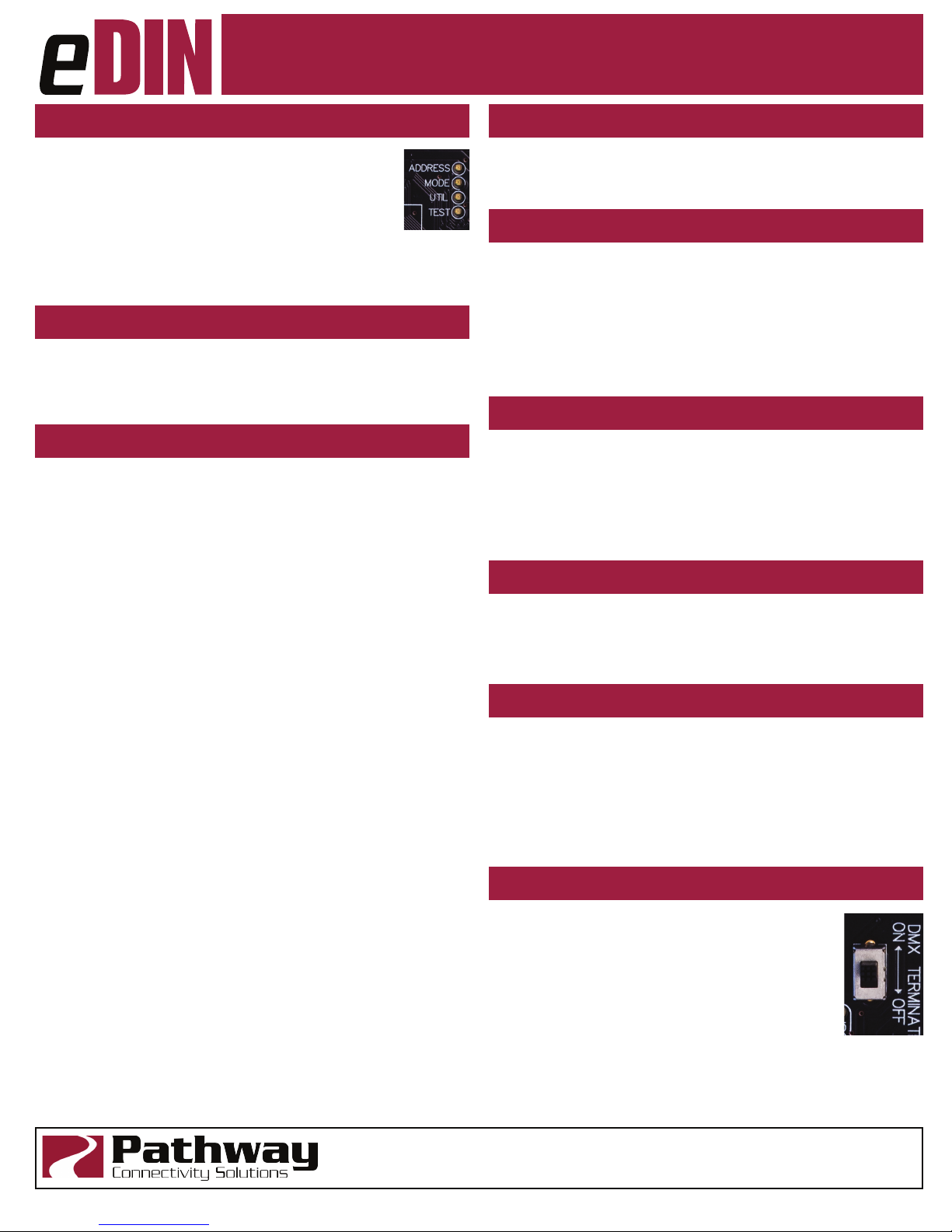
DMX TERMINATE
DMX rules require the last device on a DMX line to be
terminated with a 120Ω resistor between pins 2 and 3
to prevent signal reection. If there is no connection to
the DMX THRU terminals, the DMX Terminate switch
should be ON.
If there are other devices connected to the DMX
THRU terminal, the DMX Terminate switch should be
OFF and termination be applied to the nal device in the daisy-chain.
Pathway Connectivity Solutions
1006-200-REV1 04/25/19
#103—1439 17Avenue SE Calgary AB
Canada T2G 1J9
support@pathwayconnect.com
www.pathwayconnect.com
tel (403) 243-8110 fax (403) 287-1281
Page 3

Model 1006 24-Channel
TM
Analog to DMX
ELECTRICAL INFORMATION
• Power input: 9-30VDC, 5W maximum
• 250V Fault protection on DMX input
• 1500V Opto-isolation between DMX signal and analog/
contact inputs
• Connections (DMX):
• Compression Fit (Screw Terminal): stranded, 14-30 AWG
• IDC Connector: Cat5/6 or solid wire, 22-24 AWG
• Input Signal: ANSI E1.11 DMX512-A, ANSI E1.20 RDM
• Outputs: ANSI E1.11 DMX512-A
• Analog/Contact Inputs:
• Do not exceed 10VDC input when set as analog
inputs.
• Do not connect voltage sources when set as contact
inputs.
Exceeding this rating may result in personal injury
and/or equipment damage to this and other connected
devices.
Manual
PHYISCAL
• 0.7 lbs (0.316 kg)
• 6.25”W x 4”H x 1.55”D (159mm x 103mm x 40mm)
COMPLIANCE
• ANSI E1.11 DMX512-A(2008)/USITT DMX512(1990)
• ANSI E1.20 RDM(2010) - Remote Device Management
• ANSI E1.3 0-10V Analog Control
• RoHS 2011/65/EU
• CE
Pathway Connectivity Solutions
1006-200-REV1 04/25/19
#103—1439 17Avenue SE Calgary AB
Canada T2G 1J9
support@pathwayconnect.com
www.pathwayconnect.com
tel (403) 243-8110 fax (403) 287-1281
 Loading...