

Page 1
Model 1003 12-Relay
TM
DMX IN FROM
Contact Closure
OVERVIEW
The Pathway eDIN Contact Closure provides twelve
DMX-controlled, form-C relay closures for low voltage
power or signal switching.
RDM discoverable and congurable, with a DIN-rail mount
that makes installation fast and easy.
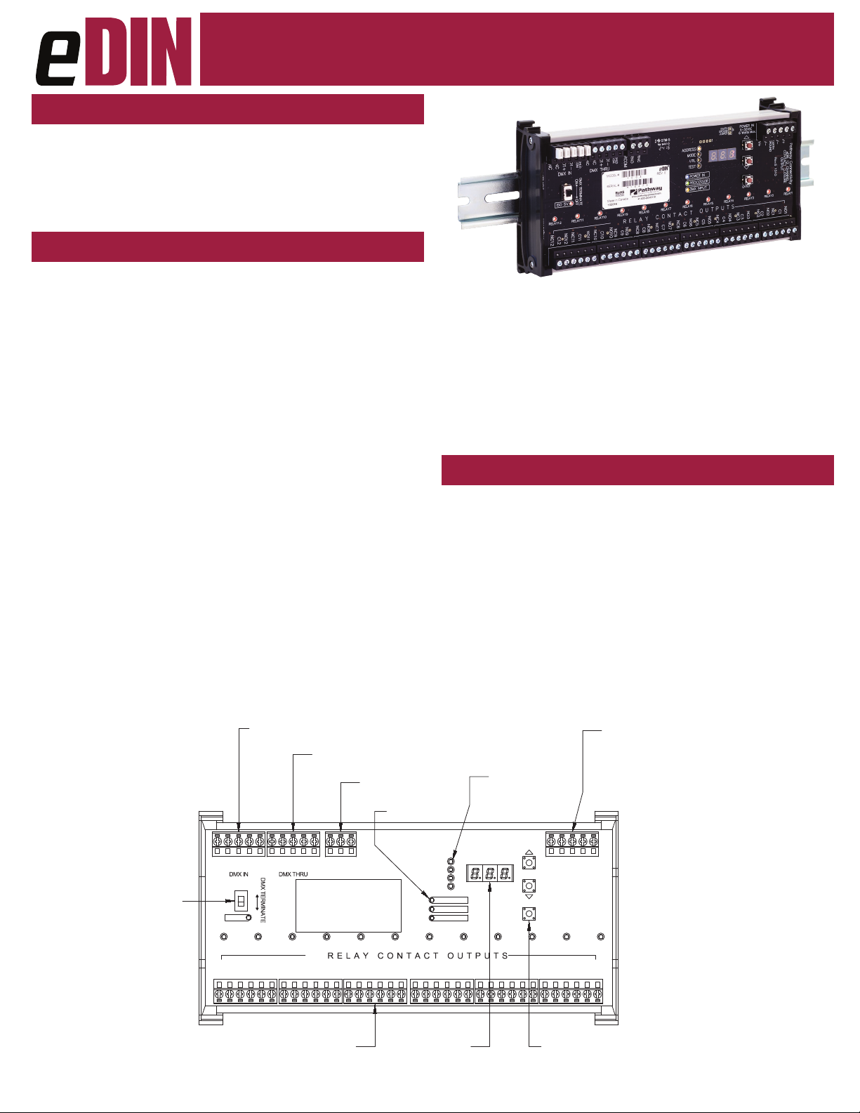
CONNECTIONS
The 1003 features terminal strips that can be removed from the
card to facilitate easy wiring installation or replacement. Make the
following connections, WITH THE POWER TURNED OFF.
POWER
The module will run on a range from 9 to 30 VDC at a maximum
of 6 Watts. Observe the correct polarity when connecting the V+
and V-. A second set of terminals are provided on the connector to
daisy-chain power to other eDIN modules. The EARTH GROUND
terminal must be connected to the enclosure’s chassis or electrical
ground terminal to ensure EMC compliance.
Manual
provide no voltage or current on their own. One connection is to the
supply and one to the load. Each relay has three sets of contacts;
normally-open (NO), normally-closed (NC), and common (C).
Generally, the normally-open contacts are used; providing an open
switch that closes when the relay is energized. Normally-closed contacts operate in the opposite manner, providing a closed switch that
opens when the relay is energized.
All common terminals are independent of one another.
DMX512
DMX connections consist of a shield and data pair.
Connect the DATA+ and DATA– wires to D1+ and D1-
respectively for each of DMX IN and DMX THRU.
Observe the same polarity convention throughout the system.
Connect the cable shield to the SHLD COM terminal.
DMX THRU may be daisy-chained to the DMX IN of other eDIN
modules.
DMX PRESENT RELAY CLOSURE
Starting with rmware 1.5.5, the J13 DMX present relay closure is
supported. Wire RCOM to RNO or RNC for normally-open or nor-
mally-closed, as desired.
CONTACT OUTPUTS
The 1003 can be thought of as twelve DMX controllable switch closures. As switches, they need two connections each, as the switches
CONTROL SYSTEM
DMX THRU TO
OTHER eDIN MODULES
RCOM
COM
SHLD
D1-
NO10
NC10
C10
NC9
NO9
C9
DMX SIGNAL
PRESENT RELAY
RNC
RNO
RELAY8RELAY9RELAY10
NO8
C8
NC8
STATUS LEDs
RELAY7
NC6
NO7
C7
NC7
END OF LINE
TERMINATION SWITCH
NCNCD1+
NC12
ISO 5V
C12
NO12
D1-
RELAY11RELAY12
NC11
ON OFF
COM
SHLD
C11
NCNCD1+
NO11
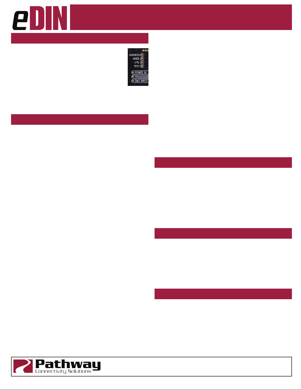
STATUS INDICATORS
POWER IN Blue. Steady glow indicates power supply OK;
o indicates no power.
PROCESSOR Green. Steady glow indicates processor is OK;
o when POWER IN is lit indicates processor
failure.
DMX INPUT Amber. Steady glow indicates port latched to ac-
tive DMX source; o indicates no signal present.
RELAY Red. Steady glow indicates relay is energized.
Flickers for momentary action.
FUNCTION Amber. Indicates the function associated with
the numeric display.
POWER IN:
9-30VDC, 5W SUPPLY REQUIRED.
USE #1001-100-24-DIN
POWER SUPPLY OR EQUAL.
ADDRESS
C6
MODE
UTIL
TEST
POWER IN
PROCESSOR
DMX INPUT
NC5
NO6
RELAY5RELAY6
NO5
C5
MENU
FUNCTION LEDs
POWER IN
9-30VDC
6 Watts Max.
C3
NC3
NO4
C4
NC4
ENTER
RELAY3
NO3
NC2
V+
V-
RELAY2 RELAY1RELAY4
C2
CONNECT EARTH GROUND TO PROTECT
DMX INPUT FROM RF INTERFERENCE
CARRIED ON CABLE SHIELD.
V+
GROUND
EARTH
V-
Pathway Connectivity
CONTACT CLOSURE
eDIN 12 CHANNEL
OUTPUT
NO1
C1
NC1
NO2
1003-300-REV1 04/04/19
NORMALLY OPEN OR CLOSED
RELAY CONTACT OUTPUTS
2A @ 30VDC MAX
(12 TOTAL)
LED NUMERIC
DISPLAY
PROGRAM
PUSHBUTTONS
Page 2
Model 1003 12-Relay
TM
Contact Closure
Manual
CONFIGURATION
The eDIN user interface has two operating modes:
Function and Edit. Press the ▲ or ▼ buttons to select a
function, indicated by the LED next to ADDRESS, MODE,
UTIL, or TEST. Once selected, press and hold the
ENTER button until a dot appears in the lower right-hand
corner of the display. The card is now in EDIT mode.
ADDRESS changes the DMX start address. MODE sets
one of nine dierent operating modes. TEST allows the user to test
the contact closures using the ▲ or ▼ buttons. Test patterns depend
on what mode the card is operating in. For UTIL mode, see the
section labeled “UTIL MODE” to the right.
SET OPERATING MODE
Once in EDIT mode, choose from the following:
• MODE 1: 12-Channel Maintained Control
Each relay is maintained “on” as long as the DMX value of its
associated channel is above 50%.
• MODE 2: 12-Channel Momentary Control
When the DMX channel for a given relay passes through the
50% threshold, either increasing or decreasing, the relay will
close for 100mS.
• MODE 3: 12-Channel Momentary “ON”
When the DMX channel for a given relay is increasing and
passes through the 50% threshold, the relay will close for 100mS.
• MODE 4: 6-Channel Momentary Split
Each adjacent pair of relays are associated with a single DMX
channel. When the DMX level of the channel for a given relay
pair passes through the 50% threshold, increasing, the lower
number relay will close for 100mS. When the DMX level for a
given pair passes through the 50% threshold, decreasing, the
higher number relay will close for 100mS.
• MODE 5: 6-Channel Maintained Split
Each adjacent pair of relays are associated with a single DMX
channel. When the DMX level of the channel for a given pair
passes through the 50% threshold, increasing, the lower number
relay will close and maintain state, while the higher number relay
will open. When the DMX level for a given pair passes through
the 50% threshold, decreasing, the lower number relay will open
while the higher number relay will close and maintain state.
• MODE 6: 12-Channel Momentary Split with Secondary
‘Reset’
2 sequential DMX channels are associated with each adjacent
pair of relays. When the lower DMX channel increases through
50%, the lower numbered relay will close for 100mS. When the
lower DMX channel decreases through 50%, the higher-numbered relay will close for 100mS. To provide a secondary reset,
when the higher DMX channel passes through 50%, increasing,
the higher relay will close for 100mS. If the higher DMX channel
decreases through 50%, the relays remain unchanged.
• MODE 7: Chase
Each relay will be triggered for two seconds. This mode is intended as a test feature, independent of the user-initiated TEST
mode.
• MODE 8: Single Channel Select
Raising the DMX level of the start channel will maintain each
relay in turn, from none up to the twelfth. At a DMX percentage
between 0-8%, no relays will be triggered; a DMX percentage
between 9-16% will maintain relay 1 only; a DMX percentage
between 17% and 24% will maintain relay 2 only; and so on. In
this mode, the Contact Closure Interface has a DMX footprint of
one channel.
• MODE 9: Single Channel Build
Raising the DMX level of the start channel will trigger each relay additionally. At zero percent, no contact closures will trigger,
while at full, all twelve contact closures are triggered. At a DMX
percentage between 0-8%, no relays will be triggered; a DMX
percentage between 9-16% will maintain relay 1 only; a DMX
percentage between 17% and 24% will maintain relay 1 and relay
2; and so on. In this mode, the Contact Closure Interface has a
DMX footprint of one channel.
UTIL MODE
Firmware 1.6.0 and higher: UTIL adjusts the DMX trigger threshold.
Valid range is 2 to 253, with a default of 128 (50%). Feature not
available on older rmware.
Firmware 1.5.5 and lower:
• UTIL Mode 1: normal operation.
• UTIL Mode 2: the number 12 relay will trigger whenever DMX
becomes present or is lost. Momentary or maintained behavior
is governed by the operating mode of the card.
TEST AND SELF-TEST
Once in TEST mode, use the ▲ or ▼ buttons to trigger the selected
relay or relay pair. The test function is operating mode dependent
and will cause the card to ‘ignore’ the DMX input.
Press the ▲ button while turning power on to enter Self-Test mode.
All LEDs will ash sequentially. The display will cycle 0 through 9,
then show the cards serial number and rmware version. Cycle
power to end self-test.
RDM RESPONDER FEATURES
The 1003 is fully compliant with ANSI E1.20 Remote Device Management as a responder device. An RDM Controller can discover
and set the card’s DMX start address, rmware version and operating mode. Starting with rmware 1.5.5, and RDM utility (Pathscape)
can upgrade the rmware in the eld.
Pathway Connectivity Solutions
1003-300-REV1 04/04/19
#103—1439 17Avenue SE Calgary AB
Canada T2G 1J9
support@pathwayconnect.com
www.pathwayconnect.com
tel (403) 243-8110 fax (403) 287-1281
Page 3

Model 1003 12-Relay
TM
Contact Closure
Manual
DMX TERMINATE
DMX rules require the last device on a DMX line to be
terminated with a 120Ω resistor between pins 2 and
3 to prevent signal reection. If there is no connection to the DMX THRU terminals, the DMX Terminate
switch should be ON.
If there are other devices connected to the DMX THRU terminal, the
DMX Terminate switch should be OFF and termination be applied to
the nal device in the daisy-chain.
ELECTRICAL INFORMATION
• Power input: 9-30VDC, 6W maximum
• 250V Fault protection on DMX input
• 1500V Opto-isolation between DMX input and module
electronics
• Connections (DMX):
• Compression Fit (Screw Terminal): stranded, 14-30 AWG
• IDC Connector: Cat5/6 or solid wire, 22-24 AWG
• Input Signal: ANSI E1.11 DMX512-A, ANSI E1.20 RDM
• Outputs: 12 normally-open/normally-closed, isolated contacts
• Contact rating: 2A @ 30VDC
Exceeding this rating may result in personal injury or
damage to this and other connected devices.
COMPLIANCE
• USITT DMX512 - 1990 / ANSI E1.11 DMX512-A
R2013
• ANSI E1.20 RDM(2010) - Remote Device
Management
• RoHS 2011/65/EU
• CE
Pathway Connectivity Solutions
1003-300-REV1 04/04/19
#103—1439 17Avenue SE Calgary AB
Canada T2G 1J9
support@pathwayconnect.com
www.pathwayconnect.com
tel (403) 243-8110 fax (403) 287-1281
 Loading...