

Page 1
HINxxy12BC/24BC/48BC
Basic Control Lighting P anel Interior
Installation and Setup
Installation Instructions
The HINxxy12BC/24BC/48BC is the lighting
control panel interior for the Basic Control
system.
The interior provides isolation between the line- and
low-voltage sections of the panel, as well as the
mounting frame for relays, the power supply and
optional control devices.
A complete panel assembly also includes one each of
the following:
1.Tub (HTUB series)
2.Cover (HCVR series)
3.Power Supply (HPSM115/277)
Santa Clara, CA 95050 © 2001 The Watt Stopper,® Inc.
Features
• From 12 to 48 plug-in relays
(Reliant Relay H2R series or GE RR series)
• Two color-coded, numbered switch/sensor terminations per relay
• Mounting holes for optional control devices
• Accessory power for optional occupancy sensors
Before starting, read the instructions on the next
three pages. If you have any questions, call our
Service Team at: 888-852-2778.
Retain these instructions and the completed
WIRING SCHEDULE card in the plastic sleeve
affixed to the rear of the panel cover.
Page 2
HINxxy12BC/24BC/48BC Lighting Control Panel Interior — Installation and Setup
This interior is intended for field
installation within the enclosure of
another product.
Refer to installation instructions
INHTUB and INHCVR for installation
of the Watt Stopper Tubs and Covers.
The following instructions assume
that a UL listed enclosure has been
properly installed.
CAUTION: Make sure all power is off
before wiring. Do not energize wiring
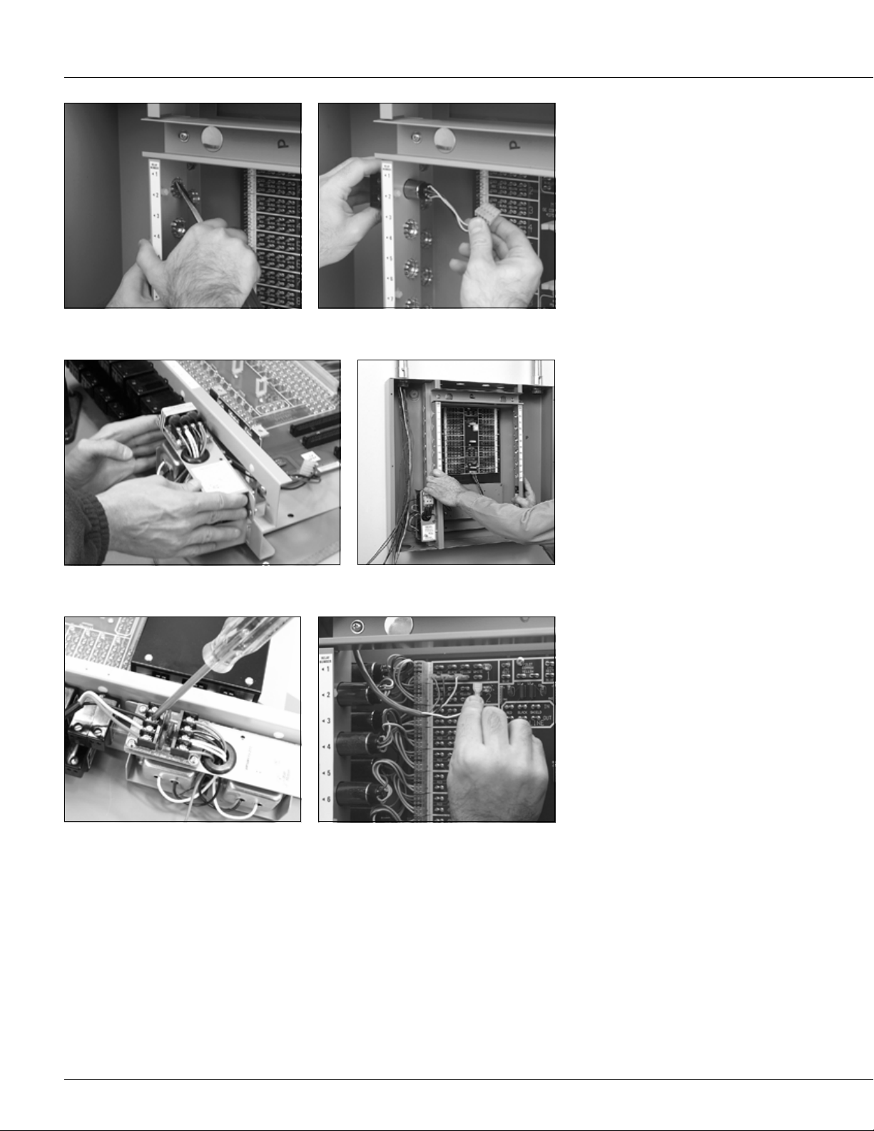
Remove knockouts as required. Install relays in the frame if necessary.
until the unit is fully assembled.
Conform to all applicable codes.
Environment
• 32° to 131°F (0° to 50°C)
• 95% relative humidity
• 15 volts/meter, 10 KHz maximum RFI
Relays
Install the power supply. Mount the interior to the studs in the tub
Making sure all power is off, connect lighting circuit
wiring to the relays and line-voltage wiring to the
power supply.
with the hardware supplied.
Connect low-voltage wiring from switches, sensors
and other input devices to the terminals on the
motherboard.
Use only Reliant Relay H2R7P/H2R9P
or GE RR7P/RR9P relays. Remove only
as many knockouts as required. From
the line-voltage side, feed the lowvoltage relay connector and leads
through the hole and plug the connector
to the appropriate relay termination on
the motherboard. Push the relay into the
hole so the retainers hold it in position.
Power Supply
Attach the HPSM115/277 power supply
to the bottom of the frame on a 12-relay
interior, or to the left side of the frame on
a 24- or 48-relay interior, and plug the
low-voltage connector to the termination
marked J1 on lower center of the
motherboard.
Mounting
Mount the interior in the tub and secure
it to the studs with the hardware supplied.
Make sure that all line- and low-voltage
wiring is confined to the appropriate areas.
2
Page 3

HINxxy12BC/24BC/48BC Lighting Control Panel Interior — Installation and Setup
Wiring
Line voltage
Before making connections to the
relays make sure that none of the
load circuits are shorted or miswired.
Connect the lighting circuits to the relay
SPST output terminals. Wire the power
supply, following the instructions which
accompany the unit. Connect the ground
wire to the stud provided in the tub.
Low voltage
Wire switches as shown in Figure 1. Wire
sensors and other low-voltage control
devices as shown in the installation
instructions accompanying the devices.
3
Use
⁄16" push-on terminals and wire ties.
Power Up and Test
Apply power to the power supply only
Figure 1 – Typical Wiring — Low-Voltage Switches
STANDARD SWITCH
LOCATION SWITCH
#20/3 AWG
1600 FEET MAXIMUM DISTANCE
HSSW3 (standard class)
HSSW3P (plenum applications)
#20/4 AWG
1600 FEET MAXIMUM DISTANCE
HOSW4 (standard class)
HOSW4P (plenum applications)
RED BLACK YELLOW WHITE
RED BLACK YELLOW WHITE
RED BLACK YELLOW WHITE
RED BLACK YELLOW WHITE
1
2
1
2
(
)
BLUE
ACCESSORY
POWER SUPPLY
24V 24V RECT WHITE
Using a low-voltage jumper attached to
any WHITE terminal, touch all of the
switch input RED terminals, and then
repeat for the BLACK terminals. The
relays should click on, then off. Confirm
by measuring the line-voltage terminations of the relay. Test the operation of
each low-voltage switch, sensor and
other control device according to the
individual installation instructions.
Test relays by touching each red and black switch
input terminal with a jumper connected to any white
terminal in the panel.
Document Wiring
Record the circuits controlled by each
relay on the Relay Schedule card
provided with these instructions and then
place it in the plastic sleeve attached to
the inside of the panel cover.
SINGLE SWITCH WITH
PILOT INDICATION
MULTIPLE SWITCHES
CONTROLLING
SINGLE RELAY
SINGLE (OR MULTIPLE)
SWITCH CONTROL
OF A GROUP
#20/4 AWG
1600 FEET MAXIMUM DISTANCE
HPSW4 (standard class)
HPSW4P (plenum applications)
#20/4 AWG
1600 FEET MAXIMUM DISTANCE
HPSW4 (standard class)
HPSW4P (plenum applications)
#20/4 AWG
MAXIMUM DISTANCE (See below)
NUMBER
RELAYS
PARALLEL
2
4
6
8
10
MAXIMUM
DISTANCE
WITH #20/4
750 FEET
325 FEET
180 FEET
110 FEET
65 FEET
FOR MORE THAN
TWO SWITCHES,
SPLICE CONTROL
LEADS
MAXIMUM
DISTANCE
WITH #16/4
1900 FEET
825 FEET
450 FEET
275 FEET
160 FEET
RED BLACK YELLOW WHITE
RED BLACK YELLOW WHITE
RED BLACK YELLOW WHITE
RED BLACK YELLOW WHITE
FOR MASTER PLATE,
USE HMSW25(P
RED BLACK YELLOW WHITE
RED BLACK YELLOW WHITE
RED BLACK YELLOW WHITE
1
2
1
2
)
Note: Relays 1, 2 and 3
are now permanently
1
wired as a group.
You can’t control them
individually.
2
If the pilot contacts are
wired in parallel as above,
turning ON any relay in
3
the group will cause the
pilot to light.
3
Page 4

HINxxy12BC/24BC/48BC Lighting Control Panel Interior — Installation and Setup
CAUTION: When the panel cover is
open, power to the panel must be off
at all times to avoid exposure to the
line-voltage wiring. If you remove the
cover while the panel is powered up,
use extreme caution. Do not touch
any wiring, particularly outside the
interior’s low-voltage barrier.
EMERGENCY SERVICE OR SUPPORT:
888-852-2778
Troubleshooting
If no relays respond to switches …
Check the power supply LEDs. If they
are off, check:
1.the power supply plug-in connection to
the motherboard terminal J1
2.the power feed circuit to the power
supply
If they are still off …
Replace the power supply.
If an individual relay does not
respond …
Remove the switch connections and
check the relay operation directly with a
jumper.
If it still does not work …
Turn off all power to the panel and
replace the defective relay.
Check power supply LEDs. Both should be on.
Test the relay. If defective, replace.
Note: The view shown above is of a Complete
Control lighting panel interior. It is representative of
Basic Control troubleshooting.
Relay Output Ratings
Both General Electric* RR7P/RR9P and
Reliant Relay* H2R7P/H2R9P relays
may be installed in The Watt Stopper
interiors, including those listed herein.
The GE R7P/RR9P relay output power
contacts are rated as follows:
20A Tungsten, 125VAC
20A Ballast, 277VAC
20A Resistive, 277VAC
1
⁄2HP @ 110-125VAC
1
1
⁄2HP@ 220-277VAC
The Reliant Relay H2R7P/H2R9P relay
output contacts are rated as follows:
20A Tungsten
20A Ballast
20A General use
1HP @ 120VAC, 50-60Hz
Compatibility with GE Total Lighting
Control enclosures
All Watt Stopper interiors are fully
compatible with respective GE tubs,
covers and power supplies as defined in
the table below. All Watt Stopper
warranties apply whether the interior is
used in a Watt Stopper or General
Electric enclosure.
The Watt Compatible Compatible
Stopper GE Tub/Co ver GE Po wer
Cat.# Cat.# Supply Cat.#
HINxxy12BC RTUB12/RCOV12xx RPWRxxx
HINxxy24BC RTUB24/RCOV24xx RPWRxxx
HINxxy48BC RTUB48/RCOV48xx RPWRxxx
In Watt Stopper interiors, the xx stands for the number of
installed relays and the y indicates the type: G for General
Electric or R for Reliant Relay.
* All trademarks are the property of the respective parties.
Panel Division 888-852-2778 INHINBC 071301
 Loading...