

Page 1
DMXRepeater User Guide
Operational Philosophy
To ensure trouble free operation, DMX512
standards require that DMX devices be installed in
a daisy chain, with no tees, wyes or stars in the
DMX wiring. However, site conditions may make
star wiring desirable or even mandatory. A Gray
Interfaces DMXRepeater permits star wiring by
making each branch of the star appear electrically
as its own entity, unaffected by the other branches
of the star. Additionally, opto-isolation circuitry
isolates each branch to prevent ground loops or
accidental damage from fault voltages on DMX
lines.
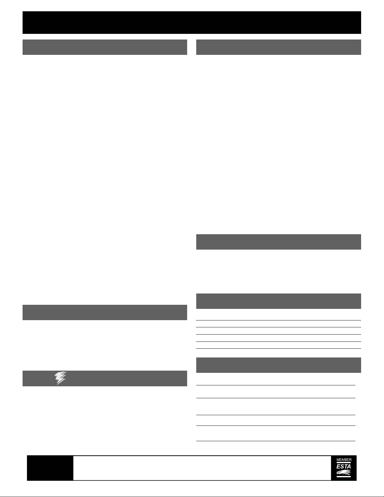
Connections
Typically, Gray Interfaces DMXRepeaters are used
in the following configuration:
• DMX Input is connected to the control
console DMX output
• DMX Outputs (A,B,C,D,E, & F) are
connected to the remote DMX devices or
receptacles for the equipment receiving the
console signal. These may be dimmers,
scrollers or moving lights, for example.
• DMX Thru passes the console signal to
additional DMXRepeaters or other similar
devices, and would in turn be connected to
DMX Input on the next unit in line. If
talkback is used, you must connect any
downstream equipment to an output
connector.
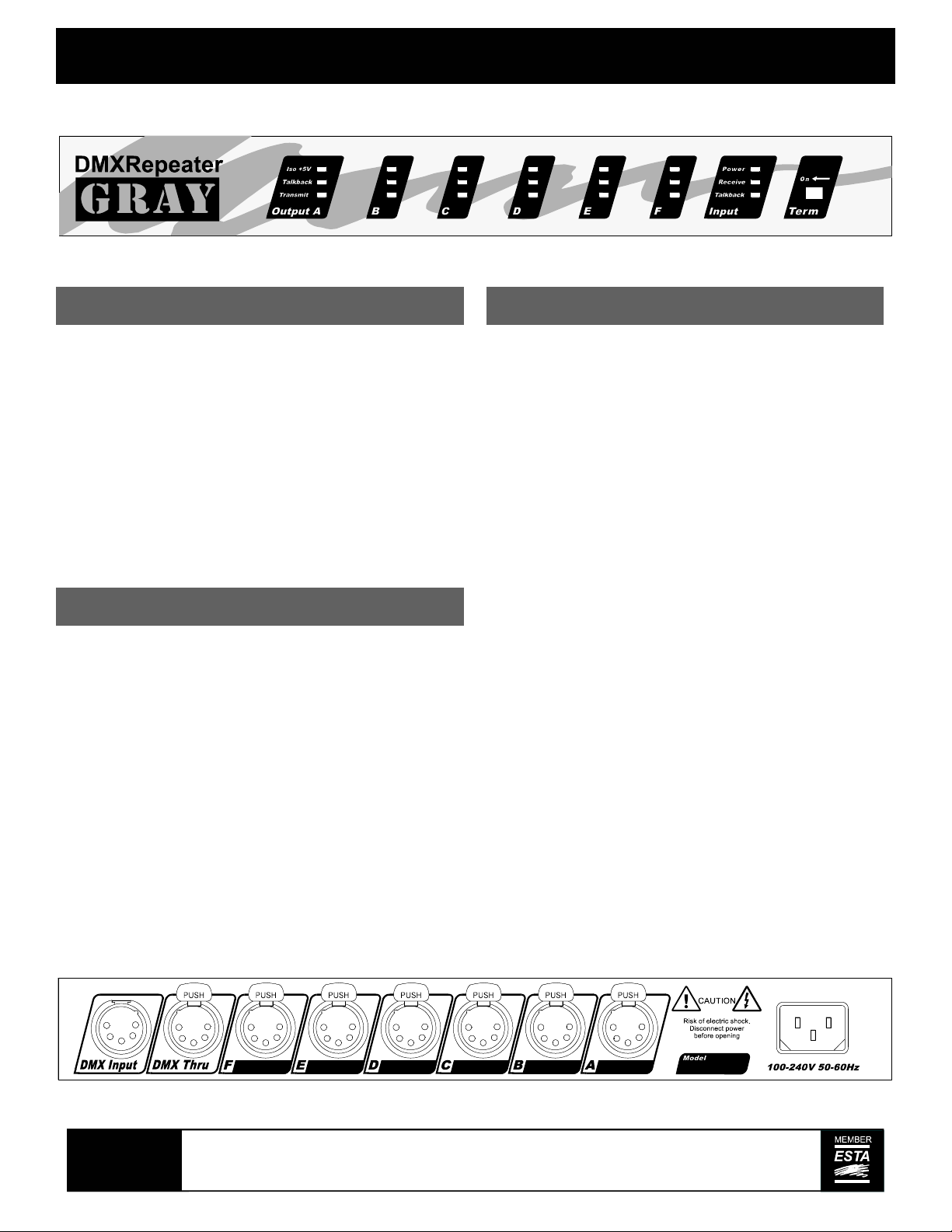
Indicators
LED indicators are provided on the face of the
DMXRepeater for diagnostic purposes. Each
group of three Output LEDs corresponds to one of
the DMX outputs from A to F. The single group to
the left of the termination switch corresponds to the
DMX input from the console.
Red LEDs are provided for the main (Input) +5 volt
power supply and the six isolated supplies (Iso
+5V), green LEDs are provided for Transmit data
and amber LEDs are provided for Received or
Talkback data, if used.
In conventional operation, the following should be
observed:
• All red LEDs should be illuminated
whenever the unit is powered.
• The amber Input Receive LED and six
green Output Transmit LEDs should
illuminate once a functioning console is
connected to DMX Input.
In addition, the following will be observed if devices
using DMX Talkback are used:
• The amber Talkback LED will illuminate at
the output section (A to F) with the
functioning Talkback device connected.
• The green Talkback LED should illuminate
at the input section.
GRAY
Pathway Connectivity, 480C - 36 Avenue S.E.,
Calgary, AB, T2G 1W4 Canada
tel (403) 243-8110 fax (403) 287-1281
Printed in Canada
support@pathwayconnect.com
www.pathwayconnect.com
Page 2
DMXRepeater User Guide continued
DMX Basics
• All wiring must be in a continuous run, daisychained, no “Tees” are permitted
• “Stars” are permitted only in conjunction with
a repeater
• Cable shield may be grounded at one end
only, preferably at the control console
• Maximum cable length is 2,000 ft.
• Receiving devices have male connectors,
transmitters have female
• 5 pin XLR type DMX connectors are
standard:
Pin 1: Common
Pin 2: Data (-)
Pin 3: Data (+)
Pin 4: Talkback Data (-) (Optional)
Pin 5: Talkback Data (+) (Optional)
• 3 pin XLR type connectors are a nonstandard alternative:
Pin 1: Common
Pin 2: Data (-)
Pin 3: Data (+)
• Wire must be Belden 9842 (120Ω), 9829,
(100Ω) or equivalent
• A maximum of 32 DMX receiving devices
can be present on a single DMX line
• The last DMX device on the line must be
terminated with a termination switch or
resistor with a value of 100 to 120 ohms
between pins 2 and 3.
DMX Termination
If only one DMXRepeater is used, and nothing is
connected to the DMX THRU receptacle, the
termination switch must be set in the direction of the
arrow (ON) to terminate the incoming DMX signal
from the console. If several DMXRepeaters are
connected together using the DMX Thru connector
on each unit, only the last DMXRepeater in the chain
is terminated, all the others are not terminated
(switch in the right position).
DMX receiving devices such as dimmers or scrollers
are generally provided with a termination switch,
termination jumper or other means of connecting the
required termination resistance across the DMX line.
Always make sure that the last receiving device
connected to any output line is properly terminated.
To ensure that the incoming console DMX signal
cannot be excessively terminated, the
DMXRepeater’s termination switch also disables the
DMX Thru connection.
Screw Terminal Connections
On the 8867 model, auxiliary screw terminal
connectors are supplied on the rear panel. The pinout
of these connectors is the same of that of 5 pin XLR
connectors. .
Rack Mounting
DMXRepeaters can be rack mounted by using an
optional 8801 19" Rack Mount bracket kit. The kit
consists of two rack mount ears that are attached
to the DMXRepeater using the 6-32 screws
included in the kit.
Power
DMXRepeaters are designed to work on voltages
from 100-240 volts AC. It will automatically sense
the incoming voltage and adjust accordingly. Be
sure to use the correct power cord if your location
requires something other than the 120V U-ground
cord included with the unit.
Pathway Connectivity, 480C - 36 Avenue S.E.,
GRAY
Calgary, AB, T2G 1W4 Canada
tel (403) 243-8110 fax (403) 287-1281
Printed in Canada
Model Description
8865 1 in - 6 out bi-directional DMXRepeater, 5 pin XLR
8863 1 in - 6 out DMXRepeater , 3 pin XLR
8863/5 1 in—6 out DMXRepeater, 3-3pin & 3-5 pin XLR
8867 1 in - 6 out DMXRepeater , terminals
8869 1 in - 6 out DMXRepeater , RJ45
Specifications
Power Supply:
Connections:
Isolation
Size:
Protocols:
support@pathwayconnect.com
Universal input (100-240V, 50/60Hz)
5 pin XLR , 3 pin XLR, terminals or RJ45
2500V Opto-isolation on DMX lines
4000V Mains isolation
13.2 x 7.8 x 1.75” (335 x 198 x 44mm)
DMX512 or any RS422 or RS485 based
www.pathwayconnect.com
09/03
 Loading...