

Page 1
DMXDecoder User Guide
Operational Philosophy
DMXDecoders convert DMX, AMX or D54
multiplexed protocols to analog control signals.
Features
• Microprocessor-based electronics
• Rotary address switch selects unit address in
one-dimmer increments
• Selectable status quo memory retention feature
maintains output levels at last known values for
five minutes upon loss of input control signal
• Auto recognition of control protocol on 24
channel models
• User-configuration positive or negative analog
outputs on 48 channel models
• LED indicators for control signal detect and
microprocessor status.
• Built in output test function allows dimmers to
be turned on from front panel switches
• 19 inch rack mount kit available
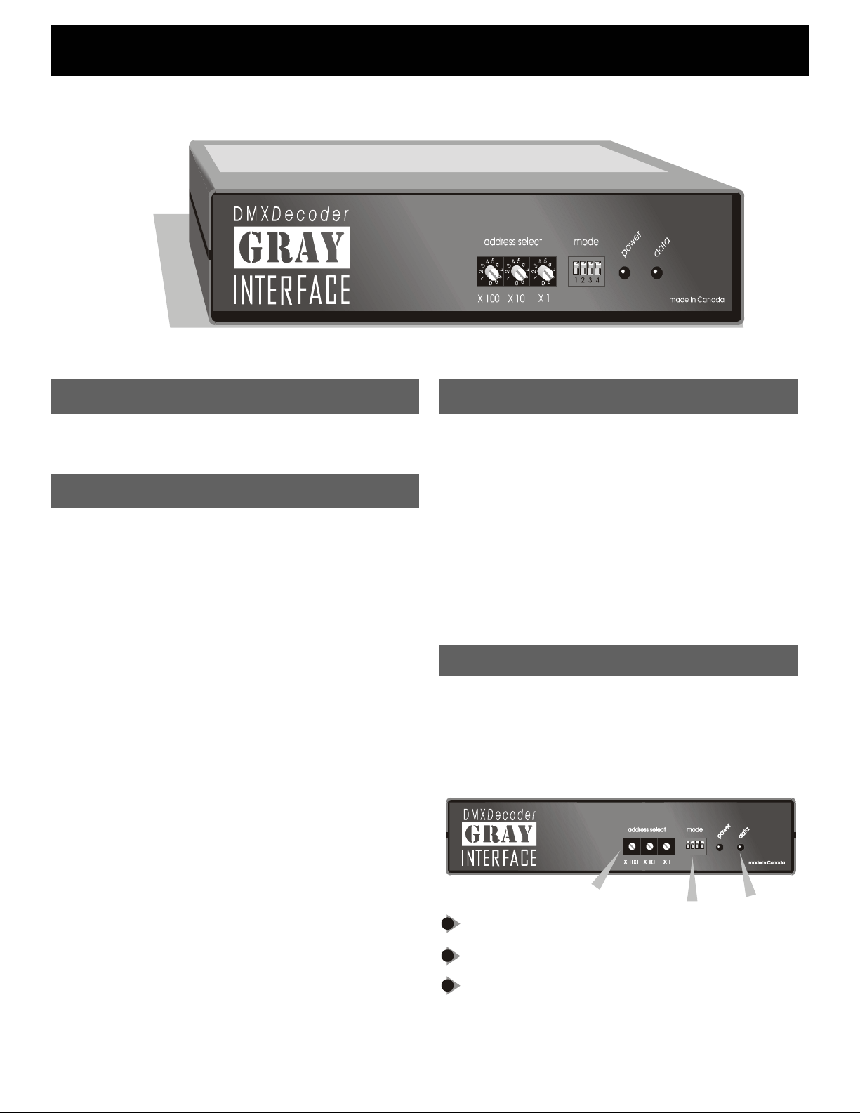
Indicators
Two LEDs are used to indicate, from left to right,
power supply and processor run status and data
receive detection.
L1 : Glowing solidly indicates power supply and
processor OK; off indicates no power, and
flashing indicates defective processor
hardware.
L2 : Glowing solidly indicates data signal received;
off indicates no signal present. Note that an
Address Selection
Three rotary switches select the offset start
address for the unit in most configurations. In test
mode, the switches set dimmers to full one at a
time. From left to right the switches are set as
hundreds, tens, and ones.
5
5
5
4
4
4
6
6
6
3
3
3
7
7
7
2
2
2
8
8
8
1
1
1
9
9
9
0
0
0
4321
1
1
Ad dress sele c t switc hes
Mode selec t DIP switc he s
2
3
LED indic ators ( power and data )
2
3
Page 2
DMXDecoder User Guide
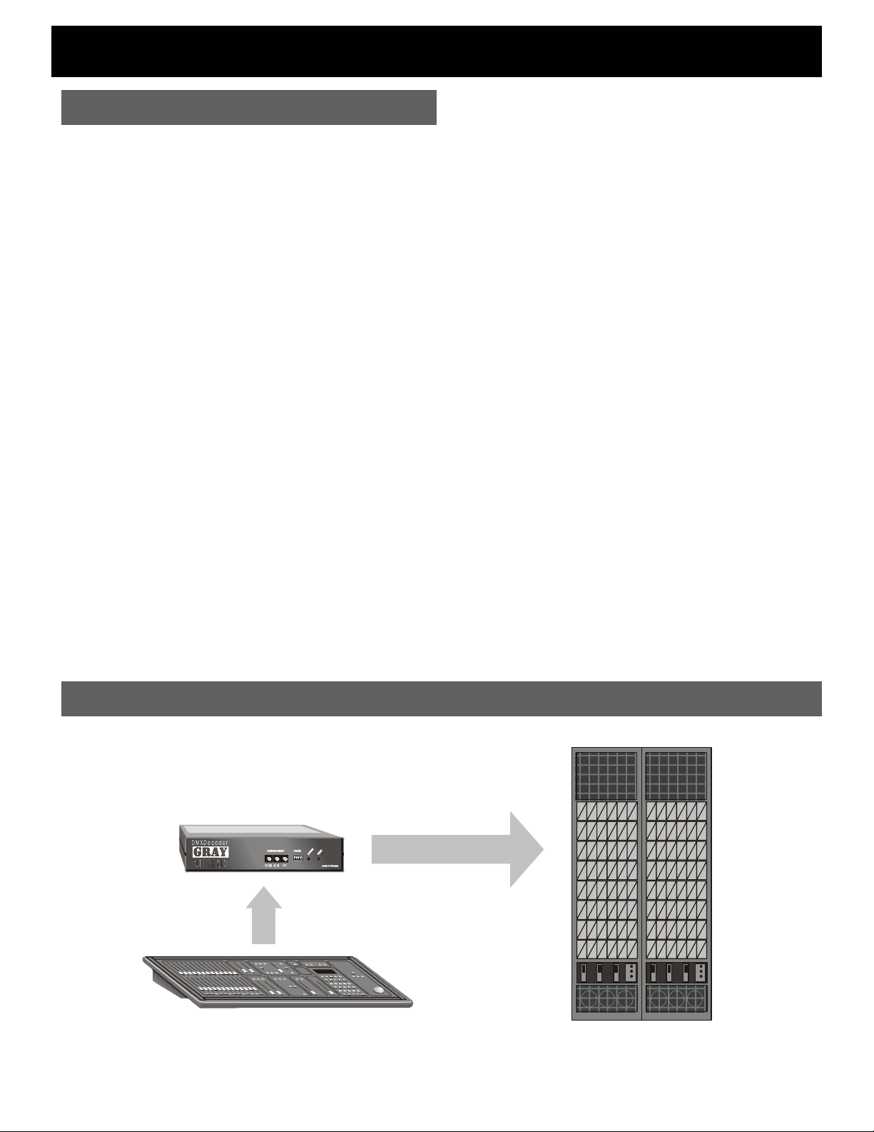
Setup Instructions
The Gray Interfaces 24 48 channel decoders have
been designed to permit easy, economical
upgrades to older lighting control systems with
analog dimmers. Standard input protocols are
USITT DMX-512 or AMX-192, or Strand D54.
A few simple steps are required to prepare your
interface unit for operation.
First, assemble your mating cables and ensure that
they conform to the connector pinouts as shown on
page . Plug the cable from your lighting control
board into the input connector on the rear panel of
the decoder unit. Note that AMX or DMX input
models include “in” and “thru” connectors, whereas
AMX and DMX input models only have “in”
connectors. The 25-pin output connector(s) of the
decoder unit wire directly to the dimmers’ analog
inputs.
Note: Unless otherwise ordered, all decoder
units are shippe d with a factory default output
configuration of 0 to 10VDC. F or other out puts,
refer to the confi guration instructions on page
4.
Next set the starting address of the first output signal
using the three rotary address select switches.
Then, refer to the DIP Switch Settings on page 4.
The shaded settings are factory defaults.
Now apply power to the decoder unit by plugging the
card from the power supply into the power jack on
the rear of the box, and plug the power cube into a
120V outlet (the decoder can be left powered up all
the time, current draw is minimal). If the
microprocessor is operating properly, the “POWER”
LED on the front panel should illuminate. Turn your
control board “DATA” LED will illuminate if the
decoder unit is receiving a valid data signal. Now run
some dimmers up to verify that the decoder is
working.
Note that in test mode (DS2 on) dimmers may be
turned on individually without the use of a control
board. Simply dial up the desired dimmer number on
the rotary address switches.
System Layout
5
5
5
4
4
4
6
6
6
3
3
3
7
7
7
2
8
2
8
2
8
1
9
1
9
1
9
0
0
0
4321
Page 3

DMXDecoder User Guide
Connector Pinout
DMX - 512
DMX PIN ASSIGNMENT
1 - COMMON
2 - DATA3 - DATA+
4 - NC
5 - NC
AMX - 192
AMX PIN ASSIGNMENT
1 - COMMON
2 - CLOCK+
3 - ANALOG
4 - CLOCK-
STRAND D54 (384)
D54 PIN ASSIGNMENT
1 - COMMON
2 - NC
3 - ANALOG
PUSH
5
4
3
4
32
1
2
OUT (F)
PUSH
1 4
IN (F)
PUSH
1
32
OUT (F)
1
2
1
1
3
IN (M)
OUT (M)
IN (M)
Analog
1 – Channel 1 & 25
5
2 – Channel 2 & 26
4
3
3 – Channel 3 & 27
4 – Channel 4 & 28
5 – Channel 5 & 29
6 – Channel 6 & 30
7 – Channel 7 & 31
8 – Channel 8 & 32
32
9 – Channel 9 & 33
10 – Channel 10 & 34
11 – Channel 11 & 35
12 – Channel 12 & 36
13 – Common
2
14 – Channel 13 & 37
15 – Channel 14 & 38
16 – Channel 15 & 39
17 – Channel 16 & 40
18 – Channel 17 & 41
19 – Channel 18 & 42
20 – Channel 19 & 43
21 – Channel 20 & 44
22 – Channel 21 & 45
23 – Channel 22 & 46
24 – Channel 23 & 47
25 – Channel 24 & 48
113
1425
Block Diagram 24 Channel Block Diagram 48 Channel
Page 4

DMXDecoder User Guide
48 Channel Decoder Card
123
JP1
JP2
JP3
JP4
P1
123
JP5
JP6
123
24 Channel Decoder Card
JP 1
JP4
JP3
OUTPUT CONNECTOR ASSIGNMENT (ALL MODELS)
If your decoder uses 25-pin D-type output con nectors, you must
DP1DP2DP3DP4DP5DP6
install JP1 on 24 channel units or JP3 on 48 channel unit s. This
will reassign the output control signals to confirm to the analog
pin assignment detail on page 3.
DIP Switch Settings
STATUS QUO HOLD TIME
Disabled (2 Sec. Time Out) OFF
Enabled ( 5 Min. Time Out) ON
Maintains last dimmer levels for set time o n loss of input data
signal
P1
TEST AND CALIBRATE MODE
When enabled allows analog dimmer out puts to be brought to
full one at a time as selected by the rotary address switch es.
PROTOCOL SELECT
AMX-192 OR D54 OFF
DMX-512 ON
JP 2
This switch is active only on 48 channel models,
1
2
3
OUTPUT CONFIGURATION (24 CHANNEL MODELS)
For 10V systems, JP2 is installed and JP3 and JP4 are
removed. For 15V systems, JP2 is removed and JP3, JP4 are
installed.
OUTPUT CONFIGURATION (48 CHANNEL MODELS)
CAUTION – Disconnect power from the unit before making
any changes
For 10V systems, JP1 and JP2 are installed: remove them for
15V systems. For positive outputs, jumper pins 2 and 3 of JP4,
5 and 6 and install diode packs DP1-6 with the notch facing
down (left). For negative outputs, jumper pins 1 and 2 of JP4, 5
and 6, and install the diode packs with the notch facing up
Before powering up, check to make sure all jumpers are
(right).
installed correctly. Damage will result if the unit is powered up
with any of the jumpers in the wrong position.
OUTPUT VOLTAGE ADJUSTMENT (ALL MODELS)
Place the unit in test mode (S1-2 on) and set the address
switches to 000 or 001. Ensure that t he decoder is connected to
dimmer no. 1 and connect a DC voltmeter between COM and
output terminal no. 1 on the circuit board. Adjust P1 to
the desired control voltage.
achieve
DMX TERMINATION
DMX Line Unterminated OFF
DMX Line Terminated ON
This switch connects a 100-ohm resi stor across the DMX data
pair. The unit should be terminated if it is the last receiving
device on the DMX line.
4
Model Description
8721 DMX input, 24 analog outputs
8721AC DMX input, 24 analog outputs with internal
100-240VAC power supply
8741 DMX input, 48 analog outputs
8600 19” rack mount bracket kit
Specifications
Power Supply:
Weight: 24 channel: 1.3 kg (2.9 lbs)
Size: 24 channel: 8 x 1.75 x 6.5” (203 x 44 x 165
9-12VDC @ 250mA (adaptor included)
48 channel: 1.5 kg (3.3 lbs)
mm)
48 channel: 8 x 1.75 x 11” (203 x 44 x 279
mm)
Pathway Connectivity Inc., 103 Inglewoo d Pla za
1439 17Avenue SE Calgary, AB, Canada T2G 1J9
tel (403) 243-8110 fax (403) 287-1281
support@pathwayconnect.com
www.pathwayconnect.com
Printed in Canada
05/02
 Loading...