

Page 1
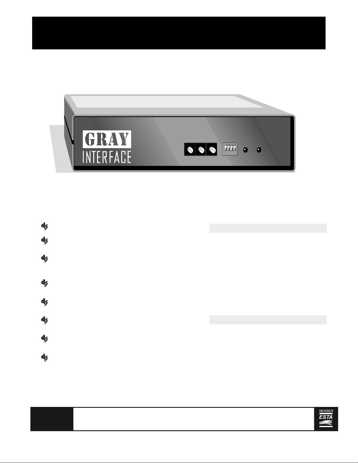
DMX ManualDecoderDMX ManualDecoder
Connect DMX512, AMX192 or Strand D54 control systems to analog dimmers
DMXDecoder
Microprocessor-based electronics
Rotary address switch selects unit address in
one-dimmer increments
Selectable status quo memory retention feature
maintains output levels at last known values for
five minutes upon loss of input control signal
Auto recognition of control protocol on 24
channel models
User-configurable positive or negative analog
outputs on 48 channel models
address select
5
5
4
4
6
6
3
3
7
7
2
2
8
8
1
1
9
9
0
0
X100 X10
mode
power
4
3
2
1
X1
5
6
7
8
9
0
4321
data
made in Canada
MODEL DESCRIPTION
8721
- DMX512 input, 24 channel output
8723
- AMX and DMX inputs, 24 channel output
8725
- D54 and DMX inputs, 24 channel output
8741
- DMX512 input, 48 channel output
8743
- AMX and DMX inputs, 48 channel output
8745
- D54 and DMX inputs, 48 channel output
8700
- 19" rack mount bracket kit
LED indicators for control signal detect and
microprocessor status
Built in output test function allows dimmers to
be turned on from front panel switches
19 inch rack mount kit available
GRAY
Gray Interfaces, 480C - 36 Avenue S.E.,
Calgary, AB T2G 1W4 Canada
tel (403) 243-8110 fax (403) 287-1281
Printed in Canada
SPECIFICATIONS
Dimensions, 24ch: 203mmx 44mmx165mm (8"x1 / "x6 / ")
48ch: 203mmx 44mmx279mm (8"x1 / "x11")
Shipping weight, 24 channel: 1.3 kg (2.9 lbs)
48 channel: 1.5 kg (3.3 lbs)
Power supply: 9-12 VDC @ 250mA (adapter incl.)
31
42
3
4
support@gray-interfaces.com
visit us at
www.gray-interfaces.com
Page 2
ABOUT THE INTERFACEABOUT THE INTERFACE
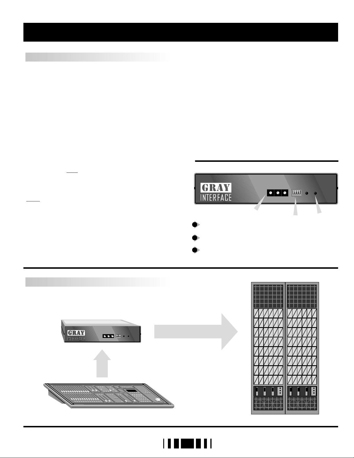
SETUP INSTRUCTIONS
The Gray Interfaces 24 and 48 channel decoders
have been designed to permit easy, economical
upgrades to older lighting control systems with
analog dimmers. Standard input protocols are USITT
DMX-512 or AMX-192, or Strand D54.
A few simple steps are required to prepare your
interface unit for operation.
First, assemble your mating cables and ensure that
they conform to the connector pinouts as shown on
page 3. Plug the cable from your lighting control
board into the input connector on the rear panel of
the decoder unit. Note that AMX or DMX input
models include “in” and “thru” connectors,
whereas AMX and DMX input models only have “in”
connectors. The 25-pin output connector(s) of the
decoder unit wire directly to the dimmers’ analog
inputs.
Note - Unless otherwise ordered, all decoder units
are shipped with a factory default output
configuration of 0 to +10VDC. For other outputs,
refer to the configuration instructions on page 4.
Next set the starting address of the first output signal
using the three rotary address select switches.
Then, refer to the DIP Switch Settings onpage 4. The
shaded settings are factory defaults.
Now apply power to the decoder unit by plugging
the cord from the power supply into the power jack
on the rear of the box, and plug the power cube
into a 120V outlet (the decoder can be left
powered up all the time, current draw is minimal). If
the microprocessor is operating properly, the
“POWER” LED on the front panel should illuminate.
Turn your control board on - the “DATA” LED will
illuminate if the decoder unit is receiving a valid
data signal. Now run some dimmers up toverify that
the decoder is working.
Note that in test mode (DS2 on) dimmers may be
turned on individually without the use of a control
board. Simply dial up the desired dimmer number
on the rotary address switches.
DMXDecoder
address select
5
4
6
3
7
2
8
1
9
0
X 100 X 10
1
1
Address select switches
Mode select DIP switches
2
3
LED indicators ( power and data )
3
2
mode
power
5
5
4
4
6
6
3
7
7
2
8
8
1
1
9
9
0
0
X 1
2
data
4321
madein Canada
3
SYSTEM LAYOUT
DMXDecoder
addressselect
5
4
6
3
7
2
8
1
9
0
X100 X10
mode
power
data
5
5
4
4
6
6
3
3
7
7
2
2
8
8
1
1
9
9
0
0
4321
X1
madein Canada
2
Page 3

FEATURES AND CONNECTOR PIN OUTS
DMX-512LED INDICATORS
Two LEDs are used to indicate, from left to right,
power supply and processor run status and data
receive detection.
L1 : Glowing solidly indicates power supply and
processor OK; off indicates no power, and
flashing indicates defective processor
hardware.
L2 : Glowing solidly indicates data signal received;
off indicates no signal present. Note that an
address selction out of the range of the data
signal will extinguish the LED.
ADDRESS SELECTION
Three rotary switches select the offset start address
for the unit in most configurations. In test mode,
the switches set dimmers to full one at a time. From
left to right the switches are set as hundreds, tens,
and ones.
ANALOG
DMX PIN ASSIGNMENT
1 - COMMON
2 - DATA3 - DATA+
4 - NC
5 - NC
AMX-192
AMX PIN ASSIGNMENT
1 - COMMON
2 - CLOCK+
3 - ANALOG
4 - CLOCK-
STRAND D54 (384)
D54 PIN ASSIGNMENT
1 - COMMON
2 - NC
3 - ANALOG
PUSH
5
4
3
1
2
OUT (F)
PUSH
4
1
32
IN (F)
PUSH
1
2
3
OUT (F)
1
2
1
1
3
5
4
3
IN (M)
4
32
OUT (M)
2
IN (M)
ANALOG PIN ASSIGNMENT
1 - CHANNEL 1, 25
2 - CHANNEL 2, 26
3 - CHANNEL 3,27
4 - CHANNEL 4, 28
5 - CHANNEL 5, 29
6 - CHANNEL 6, 30
7 - CHANNEL 7, 31
8 - CHANNEL 8, 32
9 - CHANNEL 9, 33
10 - CHANNEL 10, 34
11 - CHANNEL 11, 35
12 - CHANNEL 12, 36
13 - COMMON
14 - CHANNEL 13, 37
15 - CHANNEL 14, 38
16 - CHANNEL 15, 39
17 - CHANNEL 16, 40
18 - CHANNEL 17, 41
19 - CHANNEL 18, 42
20 - CHANNEL 19, 43
21 - CHANNEL 20, 44
22 - CHANNEL 21, 45
23 - CHANNEL 22, 46
24 - CHANNEL 23, 47
25 - CHANNEL 24, 48
BLOCK DIAGRAM 24 CHANNEL BLOCK DIAGRAM 48 CHANNEL
DMX DATAIN
AMX CLOCK IN
AMX & D54
ANALOG IN
DC
POWER
INPUT
ANALOG
TO
DIGITAL
ADDRESS
AND
DIP SWITCHES
MICRO
PROCESSOR
AND
MEMORY
RESET
5V
REG
DC-DC
CONV.
DIGITAL
TO
ANALOG
OUTPUT
SELECT
AND
LEVEL
SHIFT
WATCH
DOG
TIMER
OUTPUT
DECODE
AND
DRIVERS
1 1
ANALOG
OUTPUTS
24 48
-5V
DMX DATAIN
AMX CLOCK IN
AMX & D54
ANALOG IN
ANALOG
TO
DIGITAL
ADDRESS
AND
DIP SWITCHES
WATCH
DOG
TIMER
DC
POWER
INPUT
RESET
MICRO
PROCESSOR
AND
MEMORY
DIGITAL
ANALOG
OUTPUT
SELECT
LEVEL
VOLTAGE
POLARITY
SELECT
5V
REG
DC-DC
CONV.
DC-DC
CONV.
AND
SHIFT
AND
113
1425
TO
OUTPUT
DECODE
AND
DRIVERS
ANALOG
OUTPUTS
V+V+
+5V+5V
V-
3
Page 4
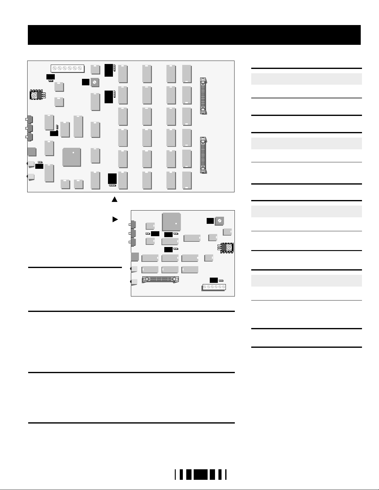
CONFIGURATION & DIP SWITCH SETTINGS
123
JP4
123
JP5
JP6
123
JP3
JP1
P1
JP2
48 CHANNEL DECODER CARD
24 CHANNEL DECODER CARD
OUTPUT CONFIGURATION
(24 channel models)
For 10V systems, JP2 is installed and
JP3, JP4 are removed. For 15V
systems, JP2 is removed and JP3, JP4
are installed.
JP1
JP4
JP3
DP1
DP2
DP3DP4
DP5
DP6
P1
JP2
STATUS QUO HOLD TIME
DISABLED (2 SECTIMEOUT)
ENABLED (5 MINTIMEOUT)
1
OFF
ON
Maintains lastdimmer levels for set time on
loss ofinput data signal.
TEST AND CALIBRATE MODE
DISABLED (NORMAL OPERATION)
ENABLED
2
OFF
ON
When enabled allows analog dimmer
outputs to be brought to full one at a time
as selected by the rotary address switches.
PROTOCOL SELECT
AMX-192 or D54
DMX-512
3
OFF
ON
This switch is active only on 48 channel
models.
DMX TERMINATION
DMX LINE UNTERMINATED
DMX LINE TERMINATED
4
OFF
ON
OUTPUT CONFIGURATION (48 channel models)
CAUTION - Disconnect power from the unit before making any changes!
For 10V systems, JP1 and JP2 are installed; remove them for 15V systems. For
positive outputs, jumper pins 2 and 3 of JP4, 5 and 6, and install diode packs DP16 with the notch facing down. For negative outputs, jumper pins 1and 2 of JP4, 5
and 6, and install the diode packs with the notch facing up. Before powering up,
check to make sure that all jumpers are installed correctly. Damage will result if
the unit is powered up with any jumpers in the wrong position.
OUTPUT VOLTAGE ADJUSTMENT (all models)
Remove the six screws from the top cover of the decoder unit,place the unit in
test mode (S1-2 on) and set the address switches to 000 or 001. Ensure that the
decoder is connected to dimmer no. 1 and connect a DC voltmeter between
COM and output terminal no. 1 on the circuit board. Adjust P1 to achieve the
desired control voltage.
OUTPUT CONNECTOR ASSIGNMENT (all models)
If your decoder uses 25-pin D-type output connectors, you must install JP1 on 24
channel units or JP3 on 48 channel units. This will reassign the output control
signals to conform to the analog pin assignment detail on page 3.
4
A 100-ohm resistor is connected across the
DMX data pair. Unit should be terminated if
it is the last receiving device on the DMX
line.
WARRANTY
WARRANTY: Gray Interfaces products are
carefully tested and inspected at the factory
and are warranted to be free of material and
workmanship defects for a period of six months
from date of shipment. Seller's warranty shall be
restricted to the repair or replacement of any
part that proves to be defective and for which a
claim is submitted to Seller before the expiration
of the applicable warranty period, providing
that this warranty shall not apply to any defect
arising from accident, misuse or improper
installation or unauthorized adjustment or repair.
Seller will not assume any responsibility for any
labour expended or materials used to replace
and/or repair any equipment without Seller's
prior written authorization. Freight terms on
warranty repairs are F.O.B. Seller's warehouse or
factory. Collect shipments or freight allowances
will not be accepted without Seller's written
authorization.
 Loading...