

Page 1
DMXManager User Guide
Operational Philosophy
DMXManager combines, merges and converts two
separate data sources into a single output.
Alternatively, it can be used as an automatic soft
switch between two data sources.
Features
• Combines two inputs on a highest takes
precedence basis
• Automatically switches from one input to
another upon loss of signal
• High performance processor
• Output address selection
• “Status Quo” feature maintains last output level
when input signal stops
• Input/output diagnostic functions
• Direct pass-thru connectors
• Sturdy all metal construction
• Optional 19” rack mount kit
Indicators
Three LEDs are used to indicate, from left to right,
power supply / processor run status, data A
receive detect, and data B receive detect. In test
mode the receive detect LEDs will flash if the input
signal is not as selected by the I/O mode switches
or if the signal is unrecognizable.
POWER:
DATA A:
DATA B:
Glowing solidly indicates power
supply and processor OK; off
indicates no power, and flashing
indicates defective processor or
control logic.
Glowing solidly indicates data signal
A received; off indicates no input
signal present.
Glowing solidly indicates data signal
B received; off indicates no input
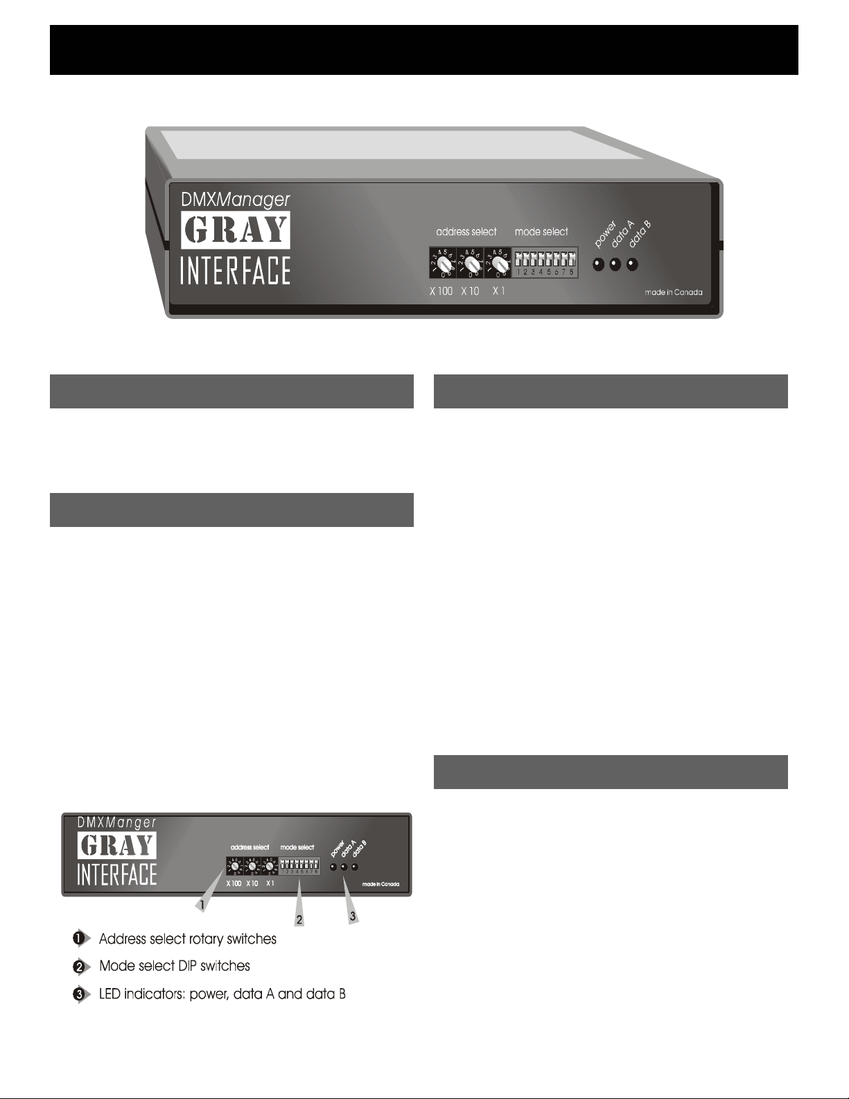
Address Selection
Three rotary switches select the offset start
address for the unit in most configurations. For
dual AMX output, the address switches select the
starting dimmer number for the second AMX output
line. In merge mode, the switches set the starting
address for the second input data line. In test
mode, the switches set dimmers to full one at a
time. From left to right the switches are set as
hundreds, tens, and ones.
Page 2
DMXManager User Guide
Setup Instructions
The Gray Interfaces Protocol Manager is designed
to permit easy, trouble free conversion between
standard USITT DMX512 and AMX192 lighting
control signals. The unit's main feature is its ability to
manage two separate lines of input data.
A few simple steps are required to prepare your
interface unit for operation. First, assemble your
mating cables and ensure that they conform to the
connector pinouts as shown on page 3. Plug the
cable or cables from your lighting control console
into the input connector on the rear panel of the
protocol manager. The output connector of the
converter box goes to your dimmer rack or other
devices, such as color scrollers.
Next set the rotary address select switches
according to the instructions on page 4. In most
applications this will be the factory default 000 or
001.
Set the first two positions of the 8-position DIP
switch according to the operating mode required. In
BACKUP mode, one or two input data lines may be
active, but the unit will read only the first. If that line
should become disabled, the Protocol Manager
automatically switches over to read the second line.
In PILE-ON mode, one or two input data lines may
be active, and the unit's output will be determined by
MERGE mode provides a means of connecting
two input signals "end to end" to create one
output signal consisting of the total number of
channels on both inputs. The most common
application of this is for two AMX192 inputs and
one DMX512 output. Another common use for
merge mode is to create an address offset
between input and output DMX data. Simply
connect the input line to Input #2 and set the
rotary address switches to the desired offset.
TEST mode is a useful diagnostic tool which
enables the user to verify Protocol Manager
input/output connections and signal integrity. The
unit will analyze the selected input protocol and
generate the selected output protocol to assist in
pinpointing network problems. More details on
test mode can be found on page 4.
Next determine the I/O (input/output) mode, eg.
DMX-in / AMX-out, and set DIP switches 3 and 4
accordingly. If two AMX outputs are required, turn
on switch 7. Note that not all I/O applications are
available on any one model of Protocol Manager.
The options available on your particular model
are listed on the label on the top of your unit.
Finally, set the desired status quo timeout with
DIP switch 5. Status quo maintains the last valid
channel levels in the event of loss of input data.
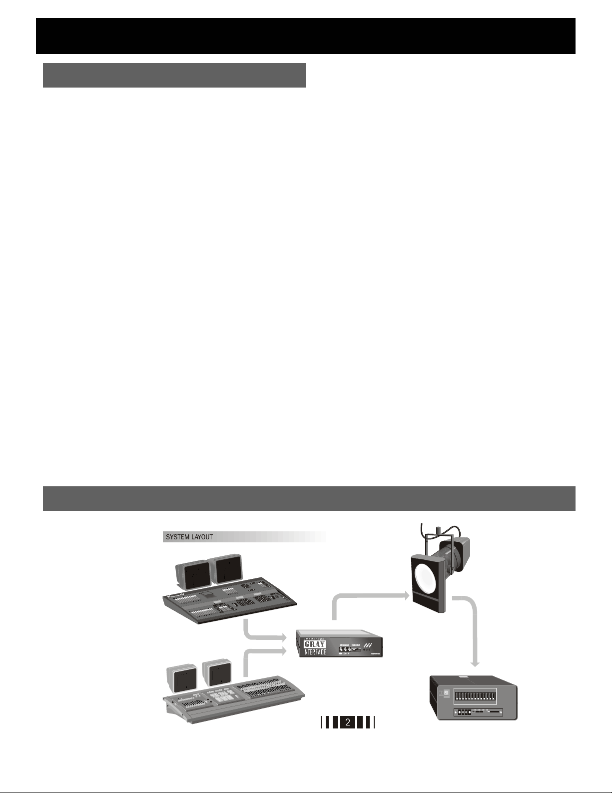
System Layout
Page 3

DMXManager User Guide
Block Diagram
Page 4

DMXManager User Guide
DIP SWITCH SETTINGS
OPERATING MODE S1-1 S1-2
BACKUP
A signal present on input A will have full control of the output, and any
signal at input B will be ignored. If the A signal is lost, the output will be
controlled by input B. The address switches will offset both inputs.
PILE-ON
Signals present at both inputs will have control of the output. The highest
level on any individual device channel on either input will be in control of
the output level. The address switches will offset input B only.
MERGE
Input B is appended to input A to create one continuous output consisting
of the total number of device channels on both inputs. The address
switches will offset input B only.
TEST MODES (determined by I/O mode)
Input Test: Receive data LEDs indicate correct data signal (on steady),
faulty or incorrect signal (flashing), or absence of any signal (off).
Output Test: The selected protocol is transmitted and the device channel
assigned by the address switches is set to full or cycled as per switch S1-
8.
I/O MODE S1-3 S1-4
DMX INPUT – DMX OUTPUT ON ON
DMX INPUT – AMX OUTPUT OFF ON
AMX INPUT – AMX OUTPUT ON OFF
AMX INPUT – DMX OUTPUT OFF OFF
STATUS QUO OPTION
STATUS QUO ENABLED
Output data remains active at last valid levels for 5 min.
STATUS QUO DISABLED OFF
Output data fails 2 seconds after loss of input data
CALIBRATE MODE
D/A OUTPUT ENABLED ON
Analog output level (5.0V) can be tested at the AMX output (pin 3) using a
DC voltmeter: no other functions are active
D/A OUTPUT CHECK DISABLED OFF
DUAL AMX OUTPUT
DUAL AMX OUTPUT ENABLED ON
DUAL AMX OUTPUT DISABLED OFF
TEST CYCLE MODE
TEST CYCLE ENABLED
Ramps the selected dimmer up and down continuously between zero and
full when in test mode.
TEST CYCLE DISABLED OFF
The selected dimmer is set to full when in test mode.
ON ON
OFF ON
ON OFF
OFF OFF
S1-5
ON
S1-6
S1-7
S1-8
ON
Connector Pinouts
Model Description
8603 2 x DMX inputs / 1 x DMX output
8605 3 x DMX inputs / 1 x DMX output
8600 19” rack mount bracket kit
AC Included 115/230VAC power supply, installed
Specifications
Power Supply:
Weight: 3 lbs (1.3 kg)
Size: 8 x 1.75 x 6.5” (203 x 44 x 165mm)
Protocols: DMX512 or any RS422 or RS485 based
USA & Canada: 9VDC external adaptor
included.
Export: 9VDC 200mA external adaptor
required
Included AC version: 115/230VAC
50/60Hz
protocol
Pathway Connectivity Inc., 103 Inglewood Plaza
1439 17Avenue SE Calgary, AB, Canada T2G 1J9
tel (403) 243-8110 fax (403) 287-1281
support@pathwayconnect.com
www.pathwayconnec t.com
Printed in Canada
05/02
 Loading...