

Page 1
DMX ManualManagerDMX ManualManager
DMXManager
address select mode select
5
4
3
2
1
0
X 100 X 10
DMX combines, merges and converts
Manager
two separate data sources into a single output.
Alternatively, it can be used as an automatic softswitch between two data sources.
Features:
Combines two inputs on a highest takes
precedence basis
Automatically switches from one input to
another upon loss of signal
High performance processor
power
data A
5
5
4
4
6
7
8
9
6
6
3
3
2
7
7
2
8
8
1
1
9
9
0
0
X1
54321678
data B
madein Canada
MODEL DESCRIPTION
8601
- 2 x AMX inputs / DMX output
8602
- 2 x DMX inputs / 2 x AMX outputs
8603
- 2 x DMX inputs / DMX output
8600
- 19" rack mount bracket kit
Output address selection
"
Status Quo" feature maintains last output
level when input signal stops
DMX512/AMX192 models
Input/output diagnostic functions
Direct pass-thru connectors
Sturdy all metal construction
Optional 19" rack mount kit
GRAY
Gray Interfaces, 480C - 36 Avenue S.E.,
Calgary, AB T2G 1W4 Canada
tel (403) 243-8110 fax (403) 287-1281
Printed in Canada
AC
- Optional 115/230VAC power supply,
installed
SPECIFICATIONS
Dimensions: 8"x1.75"x6.5"(203mmx44mmx165mm)
Shipping weight : 3 lbs (1.3Kg)
PowerSupply:
USA&Canada:9VDCexternaladapterincluded
Export:9VDC 200mAexternaladapterrequired
OptionalACversion:115/230VAC50/60Hz
support@gray-interfaces.com
visit us at
www.gray-interfaces.com
Page 2
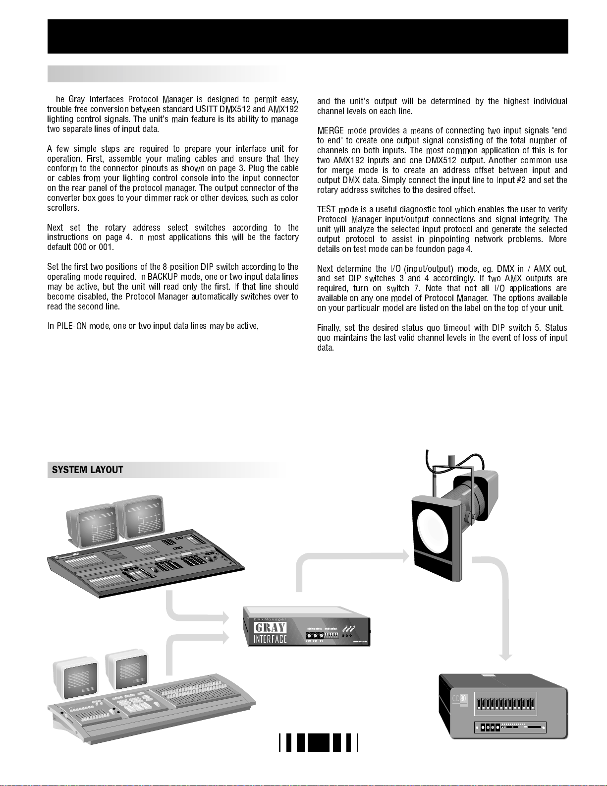
ABOUT THE INTERFACE
SETUP INSTRUCTIONS
T
he Gray Interfaces Protocol Manager is designed to permit easy,
trouble free conversion between standard USITT DMX512 and AMX192
lighting control signals. The unit's main feature is its ability to manage
two separate lines of input data.
A few simple steps are required to prepare your interface unit for
operation. First, assemble your mating cables and ensure that they
conform to the connector pinouts as shown on page 3. Plug the cable
or cables from your lighting control console into the input connector
on the rear panel of the protocol manager. The output connector of the
converter box goes to your dimmer rack or other devices, such as color
scrollers.
Next set the rotary address select switches according to the
instructions on page 4. In most applications this will be the factory
default 000 or 001.
and the unit's output will be determined by the highest individual
channel levels on each line.
MERGE mode provides a means of connecting two input signals "end
to end" to create one output signal consisting of the total number of
channels on both inputs. The most common application of this is for
two AMX192 inputs and one DMX512 output. Another common use
for merge mode is to create an address offset between input and
output DMX data. Simply connect the input line to Input #2 and set the
rotary address switches to the desired offset.
TEST mode is a useful diagnostic tool which enables the user to verify
Protocol Manager input/output connections and signal integrity. The
unit will analyze the selected input protocol and generate the selected
output protocol to assist in pinpointing network problems. More
details on test mode can be foundon page 4.
Set the first two positions of the 8-position DIP switch according to the
operating mode required. In BACKUP mode, one or two input data lines
may be active, but the unit will read only the first. If that line should
become disabled, the Protocol Manager automatically switches over to
read the second line.
In PILE-ON mode, one or two input data lines may be active,
SYSTEM LAYOUT
Next determine the I/O (input/output) mode, eg. DMX-in / AMX-out,
and set DIP switches 3 and 4 accordingly. If two AMX outputs are
required, turn on switch 7. Note that not all I/O applications are
available on any one model of Protocol Manager. The options available
on your particualr model are listed on the label on the top of your unit.
Finally, set the desired status quo timeout with DIP switch 5. Status
quo maintains the last valid channel levels in the event of loss of input
data.
DMXManager
addressselect mode select
5
5
5
4
4
4
6
6
6
3
3
3
7
7
7
2
2
2
8
8
8
1
1
1
9
9
9
0
0
0
X1
X100 X10
2
power
dataA
dataB
54321 678
madein Canada
CD
80
Page 3

ABOUT THE INTERFACE
DMXManger
address select mode select
5
5
5
4
4
4
6
6
6
3
3
3
7
7
7
2
2
2
8
8
8
1
1
1
9
9
9
0
0
0
X1
X 100 X10
1
1
Address select rotary switches
Mode select DIP switches
2
3
LED indicators: power, data A and data B
54321678
2
power
data A
3
data B
made in Canada
ADDRESS SELECTION
Three rotary switches select the offset start address for the unit in most
configurations. For dual AMX output, the address switches select the
starting dimmer number for the second AMX output line. In merge
mode, the switches set the starting address for the second input data
line. In test mode, the switches set dimmers to full one at a time. From
left to right the switches are set as hundreds, tens, and ones.
LED INDICATORS
Three LEDs are used to indicate, from left to right, power supply /
processor run status, data A receive detect, and data B receive detect.
In test mode the receive detect LEDs will flash if the input signal is not
as selected by the I/O mode switches or if the signal is unrecognizable.
POWER : Glowing solidly indicates power supply and
processor OK; off indicates no power, and
flashing indicates defective processor or
control logic.
DATA A : Glowing solidly indicates data signal A received;
off indicates no input signal present.
DATA B : Glowing solidly indicates data signal B received;
off indicates no input signal present.
BLOCK DIAGRAM
DMX DATA A IN
AMX CLOCK IN
DMX DATA B IN
AMX1 ANALOG IN
AMX2 ANALOG IN
DC
POWER
INPUT
UART
ANALOG
TO
DIGITAL
ADDRESS
AND
DIP SWITCHES
+12V
MICRO
PROCESSOR
ADDRESS/ DATA BUS
MEMORY
+5V
REG
DC-DC
CONV.
RESET
WATCHDOG
TIMER
DIGITAL
TO
ANALOG
+5V
-12V
DMX DATA OUT
AMX CLOCK 1 OUT
DMX DATA OUT
AMX CLOCK 2 OUT
AMX1 ANALOG OUT
AMX2 ANALOG OUT
-5V
3
-5V
REG
Page 4

DIP SWITCH SETTINGS & CONNECTOR PINOUTS
DMX - 512
1 - COMMON
2 - DATA3 - DATA+
4-NC
5-NC
AMX - 192
1 - COMMON
2-CLOCK+
3 - ANALOG
4-CLOCK-
STRAND D54 (384)
1 - COMMON
2 - NC
3 - ANALOG
PUSH
5
4
3
PUSH
4
32
IN (F)
PUSH
2
OUT (F)
1
1
2
2
1
1
OUT (M)
1
1
3
3
IN (M)
I/O MODE
DMX input - DMX output
5
4
3
DMX input - AMX output
AMX input - AMX output
AMX input - DMX output
STATUS QUO OPTION
STATUS QUO enabled
4
Output data remains active at last valid levels for 5 minutes
32
STATUS QUO disabled
Output data fails 2 seconds after loss of input data
CALIBRATE MODE
D/A OUTPUT CHECK enabled
2
Analog output level (5.0V) can be checked at the AMX output (pin 3)
DC voltmeter; no other functions are active
D/A OUTPUT CHECK disabled
S1-3
ON
OFF
ON
OFF
S1-4
ON
ON
OFF
OFF
S1-5
ON
OFF
S1-6
ON
using a
OFF
OPERATING MODE
BACKUP
A signal present on input A will have full control of the output, and any signal at
input B will be ignored. If the A signal is lost, the output will be controlled by
input B. The address switches will offset both inputs.
PILE-ON
Signals present at both inputs will have control of the output. The highest level
on any individual device channel on either input will be in control of the output
level. The address switches will offset both inputs.
MERGE
Input B is appended to input A to create one continous output consisting of the
total numer of device channels on both inputs. The address switches will offset
input B only.
TEST MODE
INPUT TEST
or incorrect signal (flashing), or absence of any signal (off).
: Receive data LEDs indicate correct data signal (on steady), faulty
S1-1
ON
OFF
ON
OFF
S1-2
ON
ON
OFF
OFF
DUAL AMX OUTPUT
DUAL AMX OUTPUT enabled
SINGLE AMX OUTPUT enabled
TEST CYCLE MODE
TEST CYCLE enabled
Ramps the selected dimmer up and down continuously between zero and
full when in test mode
TEST CYCLE disabled
The selected dimmer is set to full when in test mode
S1-7
ON
OFF
S1-8
ON
OFF
WARRANTY
WARRANTY: Gray Interfaces products are carefully tested and inspected at the
factory and are warranted to be free from material and workmanship defects for a
period of one year from date of shipment. Seller's warranty shall be restricted to the
repair or replacement of any part that proves to be defective and for which a claim is
submitted to Seller before the expiration of the applicable warranty period, providing
that this warranty shall not apply to any defect arising from accident, misuse or
improper or unauthorized adjustment or repair. Seller will not assume any
responsibility for any labor expended or materials used to replace and/or repair any
equipment without Seller's prior written authorization. Freight terms on warranty
repairs are F.O.B. Seller's warehouse or factory. Collect shipments or freight
allowances will not be accepted without Seller's written authorization.
OUTPUT TEST
assigned by the address switches is set to full or cycled as per switch S1-8.
: The selected protocol is transmitted and the device channel
4
PM REV.6 9606
 Loading...