

Page 1
DMX Manager Plus!
For firmware version 3.0.4.0 and higher
User’s Guide
Version 3
January 2008
Suite 103, 1439 - 17 Avenue SE
Calgary, AB, T2G 1J9
Canada
Phone: (403) 243-8110
Fax: (403) 287-1281
support@pathwayconnect.com
www.pathwayconnect.com
Page 2

DMXManager Plus!
Table of Contents
User’s Guide
About DMX Manager Plus.......................................................................................................................3
Protocols Supported ...............................................................................................................................4
DMX Port Connections............................................................................................................................4
Ethernet Port Connections .....................................................................................................................5
Basic Standalone Configuration ............................................................................................................5
Node and Network Configuration Options............................................................................................7
Port Properties and Assignments..........................................................................................................9
DMX Options ..........................................................................................................................................11
Port and Channel Patching...................................................................................................................12
LCD Backlight ........................................................................................................................................15
Security Lockout ...................................................................................................................................15
Advanced Configuration.......................................................................................................................16
Updating your DMX Manager Plus.......................................................................................................16
Appendix A – XLR Connector Pinouts ................................................................................................17
Appendix B – Menu Reference.............................................................................................................17
Appendix C – Specifications ................................................................................................................18
- 2 - Manual Version 3
Page 3

DMXManager Plus!
A
BOUT
DMX M
This manual describes the function, configuration and patching options for the
Pathway Connectivity DMX Manager Plus with firmware versions of 3.0.4.0 or
higher. Some features and menu items described below are not available in
earlier firmware releases.
The DMX512 entertainment lighting control protocol standard has become
accepted throughout the world as the standard for interoperability between
equipment supplied by most manufacturers. The DMX Manager Plus is
designed to connect with up to four independent DMX512 data streams, in a
variety of popular configurations to suit the user’s specific application. These
include:
Stand Alone Installations:
• DMX Merger: The most common stand-alone application, DMX
Manager Plus accepts up to three incoming DMX512 data streams,
merging them into one or two DMX output streams using a highestlevel-takes-precedence (HTP) mode of operation.
• DMX Patch: Individual channels within each DMX input universe can
be selectively re-mapped to outputs, allowing the user to create custom
DMX universes from all available input channels. Multiple input
channels can be assigned to a single output channel, on a merge or
priority basis.
• DMX Splitter: One incoming DMX data stream can be repeated from
up to three output ports, allowing a “star” topology to be created.
Networked Installations:
• DMX-over-Ethernet Gateway: DMX Manager Plus will function as a
four-port DMX512 gateway to or from an Ethernet control network. All
merging and channel patching features are supported in this mode.
Dual Ethernet ports allow daisy-chaining of two or more units. The DMX
Manager Plus supports Pathport® Protocol, Strand Shownet, ArtNet and
streaming ACN Ethernet protocols.
• DMX Router: Together with other compatible devices, DMX Manager
Plus will function as part of a sophisticated DMX distribution system,
where DMX input ports are selectively routed, or patched, to any DMX
output port. All merging and channel patching features are supported
in this mode.
• RDM Support: DMX Manager Plus’ bidirectional ports are compatible
with the talkback required to configure and monitor RDM-enabled
devices on a DMX512 based lighting system. Full RDM functionality
will be supported in future firmware versions.
ANAGER PLUS
User’s Guide
- 3 - Manual Version 3
Page 4

DMXManager Plus!
P
ROTOCOLS SUPPORTED
DMX Manager Plus supports the following lighting industry communication
protocols:
DMX512 – Probably the most widely used protocol for controlling lighting and
effects equipment, DMX512 was the first industry standard digital multiplex
protocol. The DMX signal consists of 512 8-bit control packets sent
asynchronously over a two-pair shielded cable at 250K Baud. The standard
connector type is 5 pin XLR. Since its inception in 1986, there have been two
revisions: USITT DMX512/1990 and the newer ANSI E1.11 DMX512-A (2005)
version. DMX Manager Plus is designed to work seamlessly with these and all
manufacturer-specific variants of the protocol.
RDM – A recent (2006) addition to the DMX512 protocol is ANSI E1.20 RDM
(Remote Device Management), a separate, optional standard which is
intended to enhance the value of DMX by adding command/query-andresponse functionality on top of the basic streaming data structure of DMX.
RDM requires that DMX ports are bi-directional. Features include remote DMX
device addressing and status reporting.
Ethernet – DMX Manager Plus is compatible with Ethernet-based control
networks using Pathport® Protocol, Strand Shownet, ArtNet and the new
streaming ACN protocol based on ANSI E1.17 ACN (Architecture for Control
Networks) Ethernet communications standard.
User’s Guide
DMX P
DMX Manager Plus provides the user with two connections, both male and
female 5-pin XLR or terminal blocks, for each of its four DMX ports. Each pair
of connectors is hard-wired in parallel. This feature allows any port to be used
as an input or output without the need for gender-swapping adapter cables.
Or, if a male-male or female-female cable is all that’s available, it will always
be a compatible cable!
It is also possible to use the second connector as a direct pass-thru for ports
configured as inputs. All five pins of each DMX connection are supported.
All connections on the four DMX ports are fully optically isolated and protected
from fault voltages. Please note that, except for the IEC chassis plug marked
for AC input, all ports on the DMX Manager Plus are intended for connecting to
low voltage data lines only.
ORT CONNECTIONS
- 4 - Manual Version 3
Page 5
DMXManager Plus!
E
THERNET PORT CONNECTIONS
For network applications, DMX Manager Plus has two 10/100 Ethernet ports
on the rear panel. The ports are connected through an internal Ethernet
switch. Use the “ETHERNET” port for the initial system connection. The
“UPLINK” port is used to daisy-chain to the ETHERNET port on the next unit.
Network configurations should be done using Pathport Manager software, a
free download from the Pathway Connectivity website. See “Advanced
Configuration” for more details.
B
ASIC STANDALONE CONFIGURATION
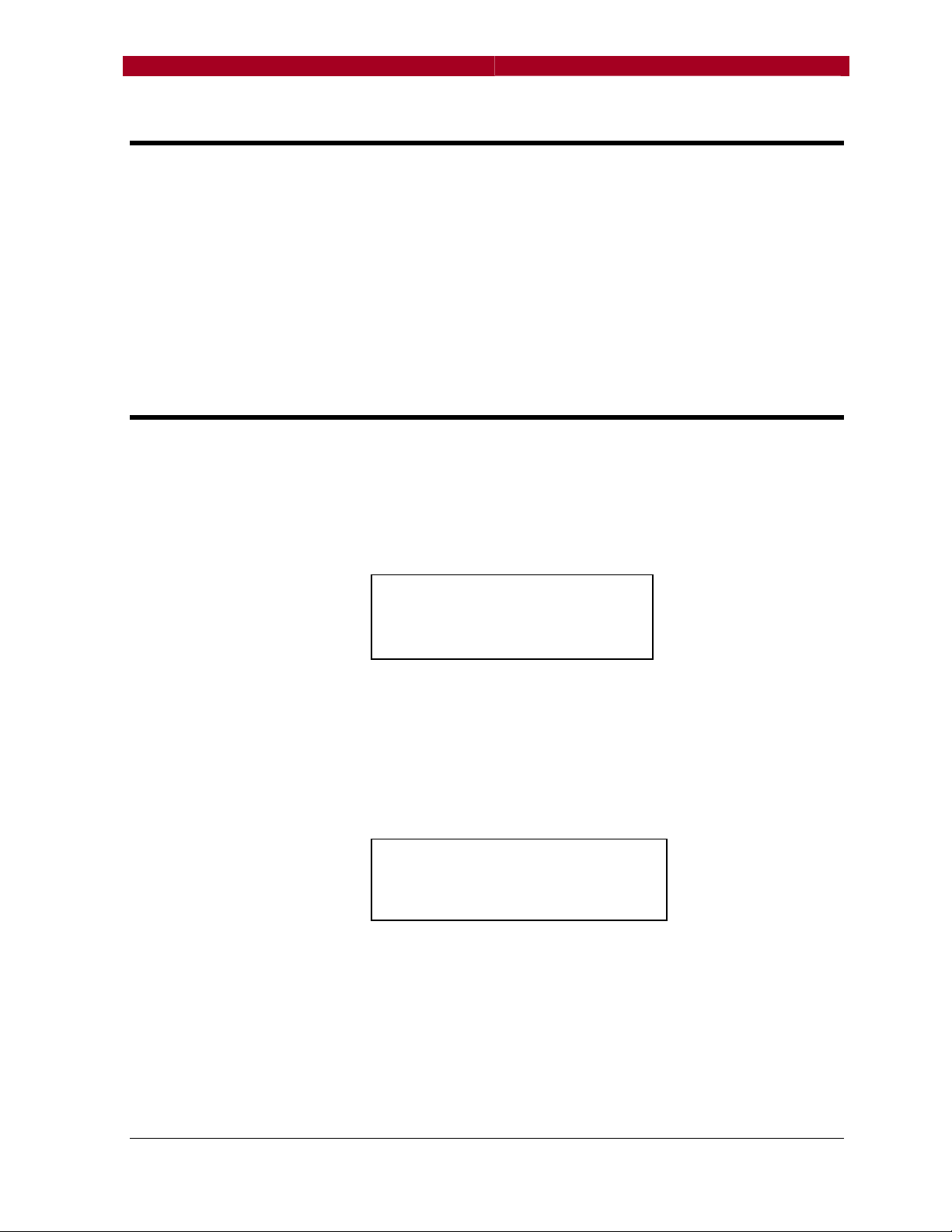
Plug in the power cord. The internal power supply will automatically sense and
accommodate any voltage and frequency from 100VAC to 240VAC and 50 to
60 Hz. The front panel liquid-crystal display (LCD) and the keypads will light
up, and the display should look similar to the following once boot-up is
complete:
Port A
Port A Input
Port APort A
Port B
Port B Input
Port BPort B
Port C
Port C Input
Port CPort C
A + B + C
A + B + C Output
A + B + CA + B + C
This is the Port Status Screen. The example above shows the factory default
configuration as a 3-to-1 merger. Ports A, B and C are configured as inputs,
and Port D is an output.
The right hand column will alternate between configuration and DMX status.
For example:
Port A
Port A No DMX A
Port APort A
Port B
Port B Active B
Port BPort B
Port C
Port C Active
Port CPort C
AAAA ++++ BBBB ++++ CCCC Active
In this example, Port A is not receiving DMX signal (e.g. no input, console
unplugged, faulty cable), while Port B and C are receiving signal which is being
output by Port D. See “Port Properties and Assignments” for other
configuration options.
Input A
Input Input
Input BBBB
Input Input
Input CCCC
Input Input
Output DDDD
OutputOutput
No DMX A
No DMX ANo DMX A
Active B
Active BActive B
Active C
ActiveActive
Active DDDD
Active Active
A
A A
C
C C
User’s Guide
- 5 - Manual Version 3
Page 6
DMXManager Plus!
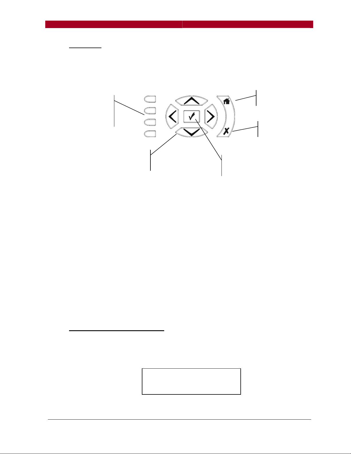
Navigation
The LCD screen also displays menus and information for configuring the DMX
Manager Plus. Common merge, split and patch functions are set and edited
using the four port-select buttons and the menu keypad.
Port Select
Buttons
A,B,C,D
The typical function of each key is as follows:
Port Select – Choose the port or menu item displayed next to the button
Up, Down – Scroll through menu options (highlight bar moves)
Left, Right – Moves cursor or go to Node Information screen
OK – Select highlighted item for editing or accept menu selection
Cancel – Do not accept menu selection
Home – Deselect highlighted item or move up one menu level
During configuration and editing, the rear illumination of each pushbutton
changes. This is intended as a contextual aid for the user. Only those buttons
that will do something are illuminated – look for back-lit port-select buttons as
shortcuts to choosing menu items.
N
ODE INFORMATION SCREEN
IP address and other information can be displayed by pressing or while in
the Port Status Screen. The Node Information Screen will appear:
Navigation
Buttons (4)
10.0.0.52
10.0.0.52
10.0.0.5210.0.0.52
User’s Guide
Home
Cancel
OK
Button
N
- 6 - Manual Version 3
Page 7

DMXManager Plus!
There are four lines of information. The top line is the node’s name, which by
default is its IP (Internet Protocol) address as set by the factory.
The second line is blank. Press the or keys to scroll through the following
items:
• Blank line (default)
• Internet protocol (IP) address and netmask
e.g.: “10.1.134.167/8”
• Media Access Control (MAC) address
e.g.: “0:4:a1:1:86:a7”
• Pathway serial number
e.g.: “PP200007”
• Firmware version
e.g.: “Version 3.0.4.1”
The bottom line is a stylized “N”. This icon blinks to indicate network activity,
otherwise it is simply on. If Ethernet protocols other than Pathport are active,
these indicators appear beside the N: “S” for ShowNet, “sA” for streaming
ACN, and “A” for Artnet.
Press √ to edit configuration options.
User’s Guide
N
ODE AND NETWORK CONFIGURATION OPTIONS
If the DMX Manager Plus is to be connected to a network, you may need to
change some of the node properties. Press √ while in the node information
display and the following menu will appear:
Configuration
Configuration
ConfigurationConfiguration
Node s
Node settings...
Node sNode s
Fa ctory
Factory
FactoryFactory
ettings...
ettings...ettings...
ssssettings...
ettings...
ettings...ettings...
Selecting “Node settings” will return this menu:
Node Settings
Node Settings
Node SettingsNode Settings
IP a
IP address...
Node
Pa thport
ddress...
IP aIP a
ddress...ddress...
Node nnnname . ..
Node Node
Pathport Protoco
PathportPathport
ame...
ame...ame...
Protocollll
Protoco Protoco
IP Address
Changes only apply in a network setting. The nature of the IP address and the
address itself can be edited from this menu using the navigation keys to select
- 7 - Manual Version 3
Page 8

DMXManager Plus!
and scroll through the options. If the IP address is set to dynamic, the address
must be supplied by a DHCP or Bootp network server whenever the power is
cycled. Generally, the use of static IP addresses is best.
Node Name
NOTE: Changing the node name does not change the unit’s IP address, only
the displayed text.
After selecting this option, the following information screen appears:
Use the appropriate port select button to choose for letter, number or symbol.
Use or to scroll to the exact character desired. Use to go to the next
character and to backspace and erase. At any time, use the port select
keys to change character types or to insert a space. Although multiple lines of
text can be entered, only the last line will actually be displayed. Approximately
15 – 20 characters will fit on one line. Press √ when done or to cancel.
Protocol Select
Use √ to select “Pathport Protocol”, then or to choose from the available
transmit protocols for DMX-over-Ethernet: Pathport, Strand ShowNet, ArtNet
or streaming ACN.
Factory Settings menu:
Factory Default
Use this option to return all settings back to the Pathway factory defaults.
Sometimes this may be the easiest way to clear a patch configuration but it will
also change the node’s name back to its IP address default.
Reboot
Reboots the DMX Manager Plus without losing any configuration information.
Letters
Letters ........
LettersLetters
Digits
Digits..............
DigitsDigits
Punctuation
Punctuation....... ....
PunctuationPunctuation
Space
Space........
SpaceSpace
Factory
Factory ssssettings
Factory Factory
Factory default
Re boot
....... .AAAA----Z, a
....... ........ .
....... .......0000----9999
....... .............. .......
....... ...........
....... ........ .
Factory default
Factory defaultFactory default
Reboot
RebootReboot
....... ....----
....... ........... ....
ettings
ettingsettings
Z, a----zzzz
Z, aZ, a
....... ...
....... .......... ...
User’s Guide
- 8 - Manual Version 3
Page 9

DMXManager Plus!
P
ORT PROPERTIES AND ASSIGNMENTS
The DMX Manager Plus ships as a three-in/one-out merger, using highest-
level-takes-precedence (HTP). This common set-up allows a console or
remote to be plugged into the system at various locations. It also allows
multiple DMX transmitters, for example an architectural controller and a
lighting console, to operate at the same time.
Because each port can be set to either input or output, the DMX Manager Plus
can be reconfigured as a one-in/three-out opto-splitter or, when used with the
channel patching features described further below, can combine two input
universes into either one or two unique and different outputs.
To reconfigure the ports, first the direction must be set, then a universe or
channel patch must be selected. While reconfiguring, menu options are
dependent on whether the port direction is set as an input or output.
If starting from factory default settings, Port D must be reconfigured first.
The following example shows how to change the DMX Manager Plus from its
default merger configuration to a one-in, three-out splitter application.
The initial Port Status Screen looks as follows (alternating with DMX status):
Port A
Port A Input A
Port APort A
Port B
Port B Input B
Port BPort B
Port C
Port C Input C
Port CPort C
A + B + C
A + B + C Output D
A + B + CA + B + C
Push the bottom port select button to choose Port D for editing. This is the
port properties screen:
Port D
Port D Output
Port D Port D
DMX options...
DMX output
Output
Output Output
Patch...
Patch...
Patch...Patch...
DMX options...
DMX options...DMX options...
DMX output
DMX outputDMX output
Patch changes should be made after setting the port direction. DMX options
will be discussed later. Press the bottom port select button to select DMX
output. The screen will change to “DMX Output”. Press either or to
change the screen to “DMX Input”, then press √ to accept the change. The
screen will return to the previous menu, which will have changed:
PPPPort D
ort D Input
ort D ort D
Patch...
Terminated
DMX in
Input
InputInput
Patch...
Patch...Patch...
Terminated
TerminatedTerminated
DMX input
DMX inDMX in
put
putput
Input A
Input AInput A
Input B
Input BInput B
Input C
Input CInput C
Output D
Output DOutput D
User’s Guide
- 9 - Manual Version 3
Page 10

DMXManager Plus!
Select “Patch”.
xDMX sources are input universes and are more fully discussed in “Channel
Patching”. Quick Patch is a universe patch, where incoming DMX is assigned
in contiguous blocks of 512 channels.
Channels 1-512 = Quick Patch 1
Channels 513-1024 = Quick Patch 2
Channels 1025-1536 = Quick Patch 3
Channels 1537-2048 = Quick Patch 4
In this example, we want one universe to be split and repeated to three outputs
so we will use only xDMX 1 and Quick Patch 1.
Select xDMX 4. Use to scroll to xDMX 1. Note if you go too far, the option
will wrap to xDMX 64. Use to scroll in the other direction. Press √ to
accept, then do the same for Quick Patch 4:
Press ‘Home’ twice to return to the Port Status Screen. Select Port C and the
screen should look like this:
Select DMX input and use the or button to change it to output. Press √ to
accept. The menu choices will have changed:
Select ‘Patch’:
Port D
Port D Pat ch
Port D Port D
XDMX source 4
Quick patch 4
Port D
Port D Pat ch
Port D Port D
XDMX source 1
Quick patch 1
Port
Port CCCC Input
Port Port
Patch...
Terminated
DMX input
Port
Port CCCC Output
Port Port
Patch...
Patch...
Patch...Patch...
DMX options...
DMX options...
DMX options...DMX options...
DMX output
DMX output
DMX outputDMX output
Patch
PatchPatch
XDMX source 4
XDMX source 4XDMX source 4
Quick patch 4
Quick patch 4Quick patch 4
Patch
PatchPatch
XDMX source 1
XDMX source 1XDMX source 1
Quick patch 1
Quick patch 1Quick patch 1
Input
InputInput
Patch...
Patch...Patch...
Terminated
TerminatedTerminated
DMX input
DMX inputDMX input
Output
OutputOutput
User’s Guide
- 10 - Manual Version 3
Page 11

DMXManager Plus!
Offset and soft patch will be discussed in “Channel Patching”. Select “Quick
patch disabled” and then use to change to Quick Patch 1 and press √ to
accept. Press ‘Home” twice to return to the Port Status Screen.
Repeat the last three steps for Ports A and B and the Port Status Screen
should look like this:
Although this example simply reversed the port directions from their factory
settings, in practice any port can be the input with the others as the outputs. It
is also possible to have two input and two output ports and, by varying the
channel patch, to use the DMX Manager Plus as a patch bay.
Port
Port CCCC Pat ch
Port Port
Offset patch
Offset patch
Offset patchOffset patch
Soft patch
Soft patch
Soft patchSoft patch
Quick patch disabled
Quick patch disabled
Quick patch disabledQuick patch disabled
Quick 1
Quick 1 Output A
Quick 1Quick 1
Quick 1
Quick 1 Output B
Quick 1Quick 1
Quick 1
Quick 1 Output C
Quick 1Quick 1
Port D
Port D Input
Port DPort D
Patch
PatchPatch
Output A
Output AOutput A
Output B
Output BOutput B
Output C
Output COutput C
Input D
InputInput
D
D D
User’s Guide
DMX O
If “DMX options” is selected from the output menu of any port, the following
screen is displayed:
Speed: The speed option specifies the refresh rate or how often the ‘dimmer’
levels are updated. The maximum DMX refresh rate is about 44 Hertz (Hz),
but some equipment behaves erratically at that rate. The DMX Manager Plus
can operate at four different refresh rates: slow (31 Hz), medium (36Hz), fast
(40 Hz) and maximum (44 Hz). The default is fast.
Termination: The DMX512 protocol requires that the last device on each DMX
line be terminated with an appropriate resistor (usually 120 ohm) to prevent
signal reflection. A port configured as an input (with no pass-thru connection)
on the DMX Manager Plus is effectively the end of that run (the signal is
optically isolated at that point) and so needs to be terminated.
But what about outputs? With the implementation of Remote Device
Management (RDM), all DMX transmitters must also be able to act as
PTIONS
Port
Port AAAA DMX options
Port Port
Fast speed
Terminated
DMX options
DMX optionsDMX options
Fast speed
Fast speedFast speed
Terminated
TerminatedTerminated
- 11 - Manual Version 3
Page 12

DMXManager Plus!
receivers – and therefore are required to be terminated as well. The DMX
Manager Plus supports the bi-directional requirements of RDM.
The only time termination should be disabled is when a port is configured as
an input and the signal is daisy-chained through the female output connector
of the same port to another device.
P
ORT AND CHANNEL PATCHING
The real power of the DMX Manager Plus lies in its ability to merge and softpatch channels both within and across universes.
Remember that each input universe must be given a different source number
and that all channel patches are created and applied at the output port only.
Although it is possible to enter all the patch information from the front panel
keypad, this interface is intended more for editing than for full-blown
configuration. The easiest way to create or extensively modify a patch is to
use the Pathport Manager software, either directly to the ETHERNET port of
the DMX Manager Plus (no crossover cable required), or over a network. See
“Advanced Configuration” for further discussion.
If you are patching your DMX Manager Plus from the front panel, please bear
in mind the limitations imposed by the use of a small LCD display.
There are three types of patching used by DMX Manager Plus: quick patch,
offset patching and soft patching.
User’s Guide
Quick Patch
This option is a basic universe patch, where an output port’s channels are
sourced from an input port as a 512 channel block. Although the DMX
Manager Plus supports 64 Quick Patch universes, to act as a 1-to-3 splitter, all
four ports must be set to the same Quick Patch, usually Quick Patch 1. As a
merger, channel levels are set on a highest-takes-precedence (HTP) basis.
To assign a quick patch to a port, go to the patch menu for that port. Select
“Quick Patch” and then use the or buttons to cycle through to the desired
universe patch number.
A quick patch will override an offset or soft patch and must be disabled to use
those other options. If the quick patch is disabled and no other patch has
been recorded, the output will appear as “Available” on the Port Status Screen
(except for Port D which defaults to ‘A + B + C’).
- 12 - Manual Version 3
Page 13

DMXManager Plus!
Offset Patch
An offset patch takes a specified range of input channels and remaps those
channels to a desired output range. This ability can be useful to append the
output of a second controller to that of a first, so an architectural controller
can’t access show dimmers for example.
The format used to create offsets follows the Pathport xDMX channel patching
philosophy. Source channels are identified by the letter of the input port, or
source universe, and the DMX channel within that universe, separated by a
decimal – for example A.52 refers to channel 52 in Universe A.
The offset command looks like this:
Universe<dot>channel start – channel end@offset channel start – end
On screen it will appear like this:
Universe: The letter of the input port – A, B, C or D. DMX Manager Plus will
not allow you to select a port that is not configured as an input. In a network
situation, universes are identified by a number between 1 and 64.
<dot>: The period or decimal place, used as a delimiter between the universe
identifier and the channel number.
Channel start: The first input channel of the range to be offset. If not
specified, defaults to channel 1.
Channel end: The last channel in the range to be offset. If not specified,
defaults to channel 512 or the highest channel possible. The default value is
not displayed unless selected for editing.
Offset channel start: Specifies the output channel to start at. Defaults to
output channel 2. It is possible to specify an output range lower than the input
range, as long as output doesn’t start at channel 1.
End: Automatically calculated from the other parameters. The end channel
value is not displayed if the default offset is used, or if the end channel is 512.
Setting an offset patch:
First the port must be configured as an output from the port properties screen.
(Remember: Port D must be set as an input before Ports A, B and C can be
set as outputs.)
Second, from the same menu, select ‘Patch’, then ‘Offset patch’. If a quick
patch is set, DMX Manager Plus will ask “Port X: Disable quick patch?” The
A.
A.11
11----17@ 52
A.A.
1111
17@52----58
17@5217@52
58
5858
User’s Guide
- 13 - Manual Version 3
Page 14

DMXManager Plus!
offset patch will not take effect unless the quick patch is disabled, so press
to accept.
The port select buttons for those ports configured as inputs will light up. Select
the one you want and the screen will change to show the universe letter and
the full channel and offset ranges. Edit with the navigation keys.
Once the range is set, press another port select button to add a range from
another input universe. This range is edited the same way. Press to
accept the patch.
Only one range per input universe can be offset.
To clear an offset range, from the offset editing screen, press the port select
button for the universe you want to clear, then press . It may be necessary
to do this twice.
S
OFT PATCH
User’s Guide
Soft patching is the full implementation of the Pathport patching philosophy,
and allows any DMX input channel from any source universe to be mapped or
patched as any channel in any output universe. Complete flexibility is
possible, especially in a networked system.
All incoming channels are placed in a pool and are referred to as xDMX
channels. Each is uniquely identified by the number of the source universe
and its channel number within that universe, separated by a decimal – for
example 4.354 refers to channel 354 in universe number 4. Up to 128
universes, for a total of 65,536 channels, are supported. Please note that
DMX Manager Plus universes A, B, C and D refer to signal input through the
XLR ports and internally are mapped to Universes 125 through 128.
Up to eight xDMX channels can be soft-patched to one output channel. The
channels will be merged on a highest-takes-precedence (HTP) basis. (A
priority patch must be set using Pathport Manager software).
Quick patch must be disabled for the port for the soft patch to take effect.
From the patch menu of the output port, select ‘Soft patch’. Down the left side
of the screen are channel numbers.
1:
1:
1:1:
2:
2:
2:2:
3:
3:
3:3:
4:
4:
4:4:
- 14 - Manual Version 3
Page 15

DMXManager Plus!
The and buttons are used to scroll up and down the channel list. All four
of the port select buttons are backlit. Press the button beside the channel
number to be patched.
A cursor will appear and now only the port select buttons for ports configured
as inputs will be backlit. Press a button to select an input or use the and
buttons to scroll through the source universe numbers. Press to highlight
the channel number then use and to edit. Press again to insert a +
character and to specify another channel. Multiple channels from the same
universe are allowed. The screen will look something like this:
Press to accept the patch for this channel, then press the port select button
next to another channel number to enter a patch for it. Press twice to save
soft patch and the home button to return to the patch menu.
If an offset patch has already been created for the port, it will appear in the soft
patch. This feature can be used to speed up soft patch creation. Conversely,
if an offset patch is created after a soft patch, it will erase the soft patch.
The navigation buttons allow access to 124 XDMX universes while creating or
editing the soft patch. They also give access to ports A, B C and D, even if
they are not configured as inputs. Be aware that it is relatively easy to map
invalid channels as inputs.
1: A.1 + B.2
1: A.1 + B.2
1: A.1 + B.21: A.1 + B.2
2:
2:
2:2:
3:
3:
3:3:
4:
4:
4:4:
User’s Guide
LCD B
ACKLIGHT
The DMX Manager Plus display backlight is normally off. To turn the backlight
on, press and hold the Home button until “Backlight on” appears. To turn off
the backlight, press the Home button until “Backlight timeout” appears. The
backlight will turn off after approximately 30 seconds.
S
ECURITY LOCKOUT
There may be situations where you do not want the settings of the DMX
Manager Plus modified. The Security Lockout feature allows you to prevent
other users from modifying any settings.
- 15 - Manual Version 3
Page 16

DMXManager Plus!
To secure the DMX Manager Plus, press and hold the cancel (X) button pad
until “Keypad locked” is displayed. The navigation buttons will now be back-lit
red. It is still possible to review the port settings, patch and node configuration.
However, any attempt to change the values will cause “Keypad locked” to be
displayed.
To turn security off, press and hold the cancel (X) button pad until “Keypad
unlocked” is displayed.
WARNING! This function is not intended to provide a high level of security. It
is simply provided as a flag to users that settings should not be casually
modified, and as a passive deterrent to unauthorized users.
A
DVANCED CONFIGURATION
The DMX Manager Plus can be viewed and configured as a Pathport device
on a standard 10/100 TCP/IP Ethernet network, using a personal computer
with Pathport Manager software installed. The computer’s LAN card can be
plugged directly into the ETHERNET port without the need of a crossover
cable or Ethernet switch.
For firmware versions greater than 3.0.4.0, Pathport Manager 4 is
recommended to create, edit and apply custom universes and complex
channel patching.
The software greatly simplifies configuration of systems including multiple DMX
Manager Pluses and multiple input universes. It is also necessary to configure
port behaviour in the event of loss of DMX signal.
For a free download of Pathport Manager 4 and complete user instructions,
visit the Pathway Connectivity website.
User’s Guide
U
PDATING YOUR
If your installation is stable, you are able to route channels as required, and
your system is DMX glitch-free, firmware upgrade is unnecessary.
Information on firmware upgrades and up-dated features, and for instructions
on the upgrade process, can be found on the Pathway Connectivity website –
www.pathwayconnect.com.
DMX M
ANAGER PLUS
- 16 - Manual Version 3
Page 17

DMXManager Plus!
2
1
5
4
3
2
1
N
A
PPENDIX A –
XLR C
ONNECTOR PINOUTS
User’s Guide
DMX512A
1 – Common
2 – Data –
3 – Data +
4 – Aux Data 5 – Aux Data +
PUSH
5
4
3
OUT (F) IN (M)
A
PPENDIX B – MENU REFERENCE
Port Status
Port A
Port A Input A
Port APort A
Port B
Port B Input
Port BPort B
Port C
Port C Input C
Port CPort C
A + B + C
A + B + C Output D
A + B + CA + B + C
Input A
Input AInput A
Input B
Input Input
Input C
Input CInput C
Output D
Output DOutput D
B
B B
Port Properties Input Port Properties Output
Port X
Port X ---- Input
Port X Port X
Patch...
Terminated
DMX Input
Input
Input Input
Patch...
Patch...Patch...
Terminated
TerminatedTerminated
DMX Input
DMX InputDMX Input
Port X
Port X ---- Output
Port X Port X
Patch...
DMX Options
DMX output
Output
Output Output
Patch...
Patch...Patch...
DMX Options
DMX OptionsDMX Options
DMX output
DMX outputDMX output
Input Patch Output Patch
Port X
Port X Patch
Port X Port X
XDMX source x
Quick Patch x
Patch
Patch Patch
XDMX source x
XDMX source xXDMX source x
Quick Patch x
Quick Patch xQuick Patch x
Port X
Port X Patch
Port X Port X
Offset Patch
Soft Patch
Quick Patch
Patch
Patch Patch
Offset Patch
Offset PatchOffset Patch
Soft Patch
Soft PatchSoft Patch
Quick Patch
Quick PatchQuick Patch
DMX Options
Por
Port X
t X DMX Options
PorPor
t X t X
Fast Speed
Terminated
DMX Options
DMX Options DMX Options
Fast Speed
Fast SpeedFast Speed
Terminated
TerminatedTerminated
Node Information
10.0.0.52
10.0.0.52
10.0.0.5210.0.0.52
Configuration
- 17 - Manual Version 3
Page 18

DMXManager Plus!
User’s Guide
Configuration
Configuration
ConfigurationConfiguration
Node settings...
Node settings...
Node settings...Node settings...
Fa ctory
Factory
FactoryFactory
settings...
settings...
settings...settings...
Node Settings Factory Settings
Node Settings
Node Settings
Node SettingsNode Settings
IP address...
IP address...
IP address... IP address...
Node name...
Node name...
Node name... Node name...
Pathport
Pathport Protocol
Pathport Pathport
Protocol
Protocol Protocol
Factory settings
Factory settings
Factory settingsFactory settings
Factory default
Factory default
Factory default Factory default
Reboot
Reboot
Reboot Reboot
A
PPENDIX C – SPECIFICATIONS
Ethernet Transmit Protocols: Pathport Protocol, streaming ACN, ShowNet, Artnet
Ethernet Receive Protocols: Pathport Protocol, streaming ACN, ShowNet, Artnet
Connectors:
Ethernet: 2 – female RJ45 to internal 10/100 Ethernet switch
DMX: 4 – male 5-pin XLR, 4 – female 5-pin XLR (1 each per port)
or 8 – Phoenix-style 5-position terminal blocks
Isolation: 2500V opto-isolation per port, 250V fault protection on DMX connectors
Fuses: Self-resetting thermal fuse
Power: 100-240VAC, 50-60Hz
Size: 432 x 152 x 44mm (17 x 6 x 1.75in)
Weight: 1.6kg (3.5lb)
Operating Temperature: 0°C - 40°C (32° to 104° F)
Operating Humidity: 10%-95% relative humidity, non-condensing
- 18 - Manual Version 3
 Loading...