

Page 1
Models 4813, 4814, 4815
An essential component of any DMX512
distribution system, DMX/RDM Installation
Splitters permit star wiring in systems required
to support E1.20 Remote Device Management
(RDM), while fully isolating and protecting
connected equipment from harmful electrical
faults of up to 2500V.
OPERATIONAL PHILOSOPHY
DMX512 standards require that DMX devices be installed
in a daisy chain, with no tees, wyes or stars in the DMX
wiring. However, site conditions may make star wiring
desirable or even mandatory.
A DMX/RDM Installation Splitter provides up to 3
eDIN modules, for a total possible 12 output branches.
Each branch acts electrically as its own entity, unaffected
by faults on other branches of the star. Opto-isolation
prevents ground loops or damage to control consoles by
fault voltages on DMX lines.
The RDM standard requires that splitters be capable of half-duplex bi-directional communication. The
standard stipulates that no more than four RDM-enabled
splitters may be daisy-chained together.
DMX/RDM Installation Splitters transparently handle all RDM data and meet the timing constraints of the
standard. Do not install RDM responder devices between
the Installation Splitter and the console.
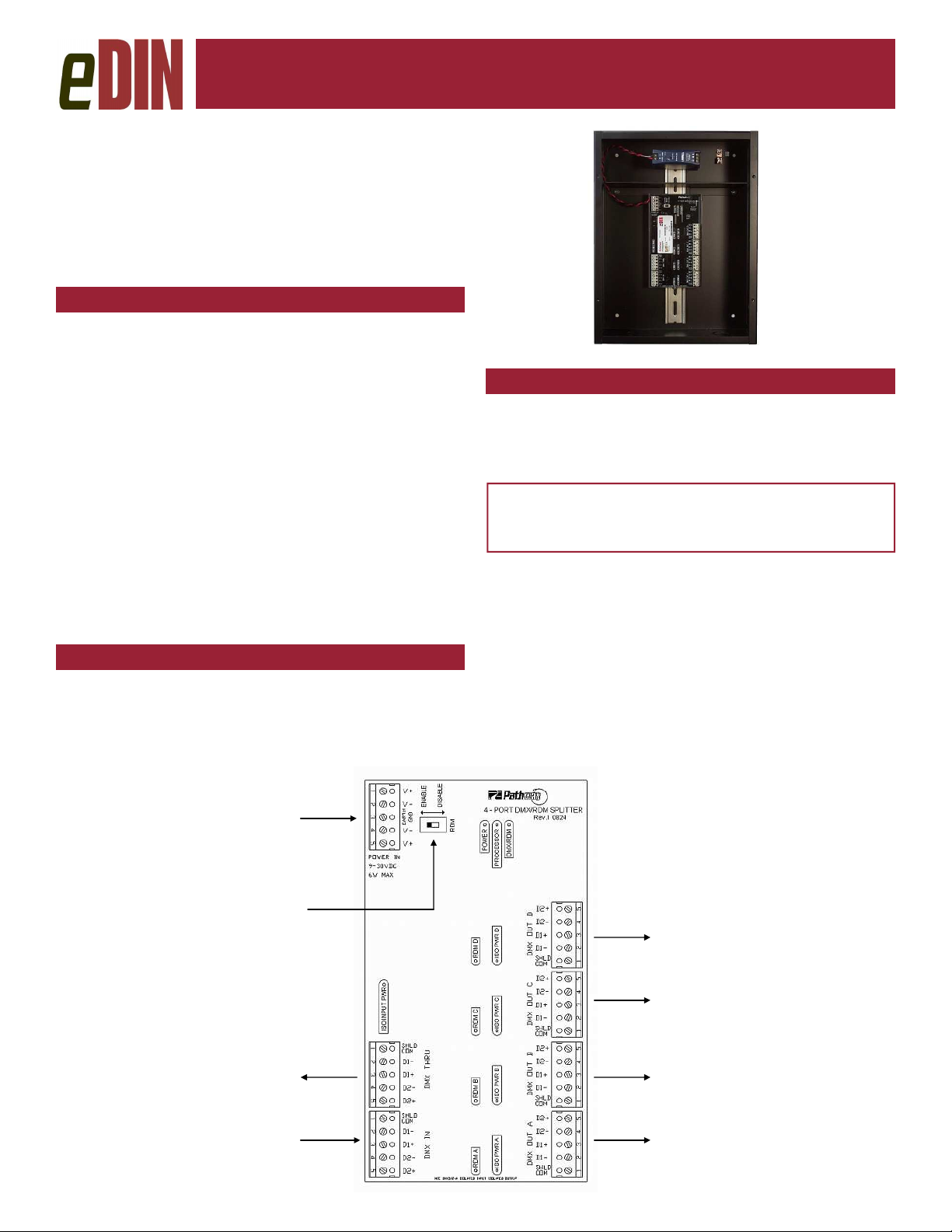
MOUNTING
DMX/RDM Installation Splitters are designed for indoor
use in a dry location. Mount the Installation Splitter to the
wall with appropriate fasteners. Run conduit into the box
through the knockouts provided, ensuring that line voltage
wiring is kept inside the barriered power supply section.
DMX/RDM Installation Splitter
DMX/RDM Installation Splitter
DMX/RDM Installation SplitterDMX/RDM Installation Splitter
Installer’s Guide
Installer’s Guide
Installer’s GuideInstaller’s Guide
Model 4813
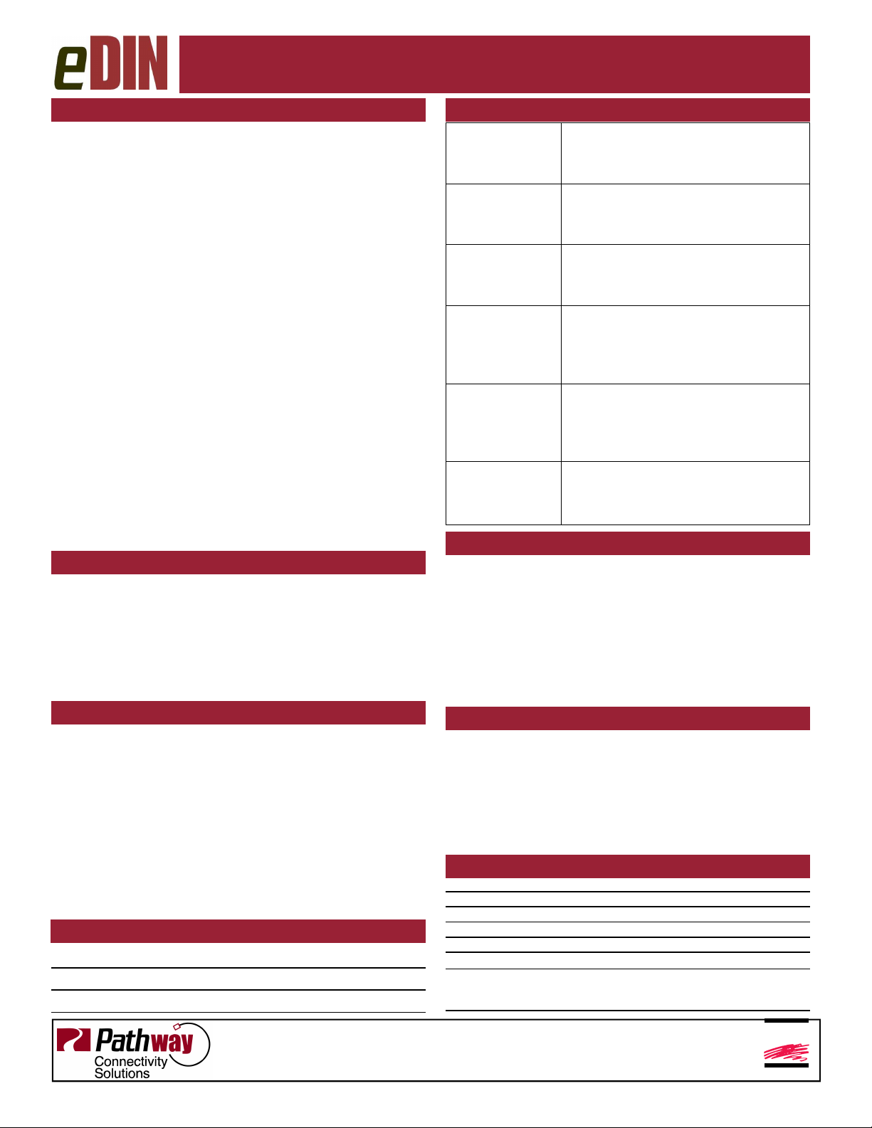
CONNECTIONS
DMX/RDM Installation Splitters are delivered with the
power supply pre-wired to the first module, and with all
required wiring daisy-chained to any additional cards.
The following connections must be done on-site.
WARNING : DMX input/output ports must be
connected to low-voltage data lines only. Do not
connect DMX ports to high voltage sources.
DMX IN is wired to the control console output or to an-
other DMX source.
DMX OUT connectors are wired to the remote DMX de-
vices, RDM responders or to receptacles for end equipment receiving the console signal. These may be dimmers, scrollers or moving lights, for example.
POWER: With the power off, make the appropriate connections to Ground, Neutral and Line screws of the power
supply in the barriered section at the top of the cabinet.
From power supply
RDM disable switch
To other eDINs or
DMX equipment
From console.
Do not install other
RDM equipment between console and
eDIN module
To DMX/RDM equipment
To DMX/RDM equipment
To DMX/RDM equipment
To DMX/RDM equipment
Page 2
ESTA
ENTERTAINMENT SERVICES &
TECHNOLOGY ASSOCIATION
Models 4813, 4814, 4815
DMX/RDM Installation Splitter
DMX/RDM Installation Splitter
DMX/RDM Installation SplitterDMX/RDM Installation Splitter
DMX WIRING
• All cabling must be in one continuous run, daisychained: no “Tees” allowed.
• “Stars” are permitted only in conjunction with a repeater or opto-splitter.
• Cable shield may be earth-grounded at one end only,
preferably at the control console.
• Maximum length of one cable segment used for DMX
only is 1,800 ft (550m). Timing constraints restrict
cable length to 1000 ft (330m) if used for RDM.
• Receiving devices have male connectors; transmitters
have female.
• The last DMX device on the line must be terminated
with a termination switch or resistor with a value of
100 to 120 ohms between pin 2 and 3. RDM capable
ports are self-terminated automatically.
• 5 pin XLR connectors are standard:
Pin 1: Common
Pin 2: Data (-)
Pin 3: Data (+)
Pin 4: Optional Data (-)
Pin 5: Optional Data (+)
• Cable must be Belden 9842 (120 Ω) 9829, 9729
(100 Ω) ISO/IEC 11801 (Cat5) or equivalent.
• A maximum of 32 DMX-receiving and/or RDM responder devices can populate a single output.
RECOMMENDED WIRING PRACTICE
Keep all DMX cabling away from high voltage/power cables to maintain data integrity. Use the appropriate wire
for all connections.
• DMX Connections: Belden 9829, 9842, Cat5 or
equivalent.
• Power Connections: Insulated #18-16 AWG, stranded
or solid core
STATUS INDICATORS
POWER IN Blue. Glowing steadily indicates
power supply OK; off indicates no
power.
PROCESSOR Green. Glowing steadily indicates
processor is OK; off when POWER IN
is lit indicates processor failure.
DMX/RDM
INPUT
ISO POWER IN Red. Indicates the internally isolated
ISO POWER
A/B/C/D
RDM A/B/C/D Amber. Flickering indicates presence
Amber. Glowing steadily indicates
data signal received; off indicates no
data signal present.
power supply for input processing is
working correctly. Off indicates no
power.
Red. Indicates internally isolated
power supply for output ports is working correctly. Off indicates no power
to that port.
of RDM data packets. Off indicates
no RDM activity on the network.
RDM ENABLE/DISABLE
This feature is not yet implemented. The switch should
be left in the ‘enable’ position.
If the RDM switch is moved to ‘disable’, the
module must have the power cycled once the switch is
returned to the ‘enable’ position.
The module is still discoverable by an RDM
controller device when the switch is in the ‘disable’ position.
EXPANSION INSTRUCTIONS
DMX/RDM Installation Splitters may hold one module
(model 4813) or up to three modules (models 4814 and
4815). If the original enclosure holds less than its limit, it
is possible to add cards. DMX THRU passes the console
signal to the additional eDIN module, where the wires are
connected to the DMX IN terminals. The DMX THRU is
fully isolated and fully supports RDM. Data and low voltage power may also be passed onto a second enclosure.
Power may be daisy-chained using the second
pair of V+ and V- terminals. Polarity should be followed
at the receiving device.
MODEL DESCRIPTIONS
4807 4-way eDIN DMX/RDM Installation Splitter
4808 8-way eDIN DMX/RDM Installation Splitter
4809 12-way eDIN DMX/RDM Installation Splitter
Pathway Connectivity Inc.,
#103 - 1439 17 Avenue SE Calgary AB Canada T2G 1J9
(403) 243-8110 fax (403) 287-1281
rev.1, ver.2
PROTOCOL COMPLIANCE
This product complies with the ANSI E1.11 DMX512-A
standard, and is backwards compliant with USITT
DMX512 1990, under the non-compatible connector
(NCC) provision.
The ANSI E1.20-2006 Remote Device Management (RDM) standard is supported as a transparent inline device and as a responding device.
SPECIFICATIONS
Power Supply: Universal input (90-250V, 50/60 Hz)
PSU Connection Screw-down terminals, 12 - 18 AWG
Data Signal: USITT DMX512/1990 and E1.11 (DMX512-A)
Isolation: 2500V opto-isolation port to port
Protection: Up to 250V on all port pins
Data Connections: Two piece compression screw terminals, 14 - 24 AWG
Size:
Models 4813 260mm x 509mm x 115mm (10.25” x 13.25” x 4.5”)
Models 4814/4815 260mm x 509mm x 115mm (10.25” x 23.25” x 4.5”)
support@pathwayconnect.com
www.pathwayconnect.com
Printed in Canada
1/10
 Loading...