

Page 1
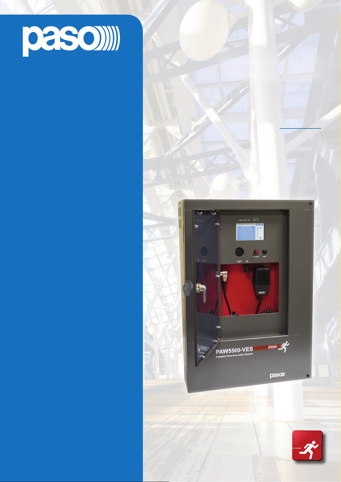
PAW5500-VES
EN54
16
Compact wall-mount
evacuation systems
Models:
PAW5502-V
PAW5504-V
PAW5506-V
User manual
Cert. EN 54-16: 2008
n° 0068/CPR/101-2018
Page 2

WARRANTY
This product is warranted to be free from defects in raw materials and assembly. The warranty period is governed by the
applicable provisions of law. PASO will repair the product covered by this warranty free of charge if it is faulty, provided
the defect has occurred during normal use. The warranty does not cover products that are improperly used or installed,
mechanically damaged or damaged by liquids or the weather. If the product is found to be faulty, it must be sent to Paso
free of charges for shipment and return. This warranty does not include any others, either explicit or implicit, and does not
cover consequential damage to property or personal injury. For further information concerning the warranty contact your
local PASO distributor.
Important! Before using the equipment, make yourself aware of all characteristics by reading carefully the instructions
included in the printed manual or on the CD, paying particular attention to the safety notes.
MODEL: .............................................................................................................................................................................
SERIAL NUMBER: ............................................................................................................................................................
PURCHASE DATE: ............................................................................................................................................................
All PASO equipment is manufactured in accordance with the most stringent international safety standards and in compliance
with European Community requisites. In order to use the equipment correctly and eff ectively, it is important to be aware of all
its characteristics by reading these instructions and in particular the safety notes carefully.
2
Page 3

PAW5500-VES
EN
TABLE OF CONTENTS
1. WARNINGS 4
1.1 Power supply and earthing 4
1.2 Safety notes 4
2. INTRODUCTION 5
2.1 Overview of the system 5
2.2 Functional features 5
2.3 Typical confi guration 6
3. GENERAL DESCRIPTION 7
3.1 Front panel 7
3.2 Inside view 8
4. INSTALLATION AND CONNECTIONS 9
4.1 Wall mounting 9
4.2 Connections 10
4.2.1 Connection of emergency units 11
4.2.2 Connection of paging units 11
4.2.3 Connection to other PAW5500-VES units 12
4.2.4 Connection of auxiliary input 12
4.2.5 Connection of music input 13
4.2.6 Connection of input contacts 13
4.2.7 Connection of relay outputs 14
4.2.8 21 to 29V connection 14
4.2.9 Connection of loudspeaker lines 14
4.2.10 Connection of standby amplifi er 15
4.2.11 Connection of power supplies 17
5. OPERATIONAL CONDITIONS AND TERMINOLOGY 18
5.1. Signalling of operating conditions 18
6. DEFINITIONS 18
7. MENU STRUCTURE 19
8. USING THE SYSTEM 20
8.1. Confi guration of the system 21
8.2. < MUSIC > Menu 25
8.3. < AUDIO SETTING > Menu 26
8.4. < INSPECTION > Menu 29
8.5. < OPERATOR > Menu 32
8.6. < CONFIGURATION > Menu 35
8.7. Criteria for managing priorities in emergency conditions 43
8.8. MANUAL emergency – < EMERGENCY > Menu 44
8.9. AUTOMATIC emergency (alarm status activated by an external peripheral unit) 46
9. FAILURE STATUS 47
9.1. System operation and signalling in a generic failure condition 47
9.2. System operation and signalling with a fault on a loudspeaker line 47
10. TECHNICAL SPECIFICATIONS 48
System manual PAW5500-VES Compact systems
3
Page 4

EN
PAW5500-VES
1. WARNINGS
1.1 POWER SUPPLY AND EARTHING
These items of equipment are intended to work on a 230 VAC +10% / -15%, 50/60 Hz mains voltage and a 24 VDC supply
from the internal batteries.
! N.B. – FEATURES OF THE WIRING SYSTEM
The mains AC power MUST be supplied through a two-pole diff erential thermal-magnetic circuit breaker with a current
of 10 to 16A dedicated SOLELY to the equipment.
! N.B.
These devices have been designed to be connected to an earthed power supply.
Make sure that the equipment is always connected to earth in accordance with legal regulations.
1.2 SAFETY NOTES
All PASO equipment is made according to the strictest international standards and complies with European Union requisites.
For correct and eff ective use of the equipment it is important to be aware of all the characteristics by reading carefully these
instructions and warnings. While the equipment is in use, it is necessary to ensure adequate ventilation, above all leaving the
slits for providing air for the cooling fans free.
REFER TO THE ‘INSTALLATION AND CONNECTIONS’ SECTION FOR THE RELEVANT PROCEDURES, TO BE CARRIED
OUT BY TRAINED SPECIALISED PERSONNEL ONLY.
Important information for correct disposal of the product in accordance with EC Directive 2002/96/EC
his product must not be disposed of as urban waste at the end of its working life. It must be taken to a special waste
collection centre licensed by the local authorities or to a dealer providing this service. Separate disposal of electric
and/or electronic equipment (WEEE) will avoid possible negative consequences for the environment and for health
resulting from inappropriate disposal, and will enable the constituent materials to be recovered, with signifi cant
savings in energy and resources. As a reminder of the need to dispose of this equipment separately, the product is
marked with a crossed-out wheeled dustbin.
This product is in keeping with the relevant European Community Directives.
PAW5500-VES Compact systems System manual
4
Page 5

PAW5500-VES
EN
2. INTRODUCTION
2.1 OVERVIEW OF THE SYSTEM
The new PAW5500-VES range incudes three integrated voice evacuation systems for emergency facilities, designed
specifi cally for wall-mounting and equipped with control units, certifi ed in compliance with EN 54-16:2008 / EN 54-4 standards.
Depending on the model, these systems are capable of managing from 2 to 6 alarm zones, each driven by a single amplifi er,
as well as remote microphone stations and controlled inputs to be connected to a central fi re-fi ghting system.
It is possible to connect up to a maximum of 6 of these systems to one other (for managing an overall maximum of 36 zones).
2.2 FUNCTIONAL FEATURES
•
Rated audio output: 500 W overall, distributable freely among the zones with a maximum limit of 250 W per single zone.
• Backlit 4.3” display with touch screen for selecting the alert and evacuation zones and enabling navigation for adjusting
volume levels, confi guring the equipment and viewing failures.
• Handheld fi reman’s paging microphone.
• Sending out of pre-recorded EVACUATION and ALERT messages.
• Sending out of pre-recorded BROADCAST messages (i.e. spots, announcements, sound bells).
• Playing back of pre-recorded messages via monitor loudspeaker.
• 7 off controlled input contacts, confi gurable for playing the evacuation and/or alert messages to the programmed zones or for
resetting the messages.
• 1 off music input for sound sources.
• 1 off auxiliary input confi gurable as a music source, a call with precedence activation or a call with automatic activation (VOX).
• 3 off confi gurable relay outputs.
• Double A+B output for each zone.
• Event log (list of failures and/or alarms that have occured in the system).
• Double LINK line for connecting other PAW5500-VES (up to a total of 6 units).
• Multilanguages management.
• Protected local button for placing the system in an emergency state, equipped with its own LED.
• Local reset button.
• 3-band equalisation for each zone output.
• 3-band equalisation for each music input.
• Optional internal expansion card ACPAW-2IN for two additional music inputs (EXT 1 and EXT 2).
• Optional internal expansion card ACPAW-6IN with DSP for six additional music inputs.
• Built-in SD/USB input for background music MP3 player.
• Independent selection on each zone of the various audio sources (MUSIC IN, AUX IN, MP3 player and EXT).
• Up to 8 pre-recorded messages can be retrieved from outside through input contacts (of which 2 fi xed emergency messages
- plus 6 that can be classed as emergency / evacuation / broadcast messages).
• Possibility of setting up to 16 timers for the programmed playing out of the broadcast messages with the possible activation of
signalling relays.
• Up to 16 PMB106-G and/or PMB112-G broadcasting microphone stations can be connected.
• Up to 4 of the above mentioned stations can be set for local calls only (zones of the card-cage to which they are connected).
• Up to 4 PMB132-V and PMB132/12-V remote emergency units can be connected (or, as an alternative, up to 2 touch screen
units TSB8500-V).
• EN54-4 certifi ed battery charge unit for 24VDC secondary power supply (batteries not included).
• Mounting on 19” rack (optional, with ACPAW-RCK accessory kit).
System manual PAW5500-VES Compact systems
5
Page 6
EN
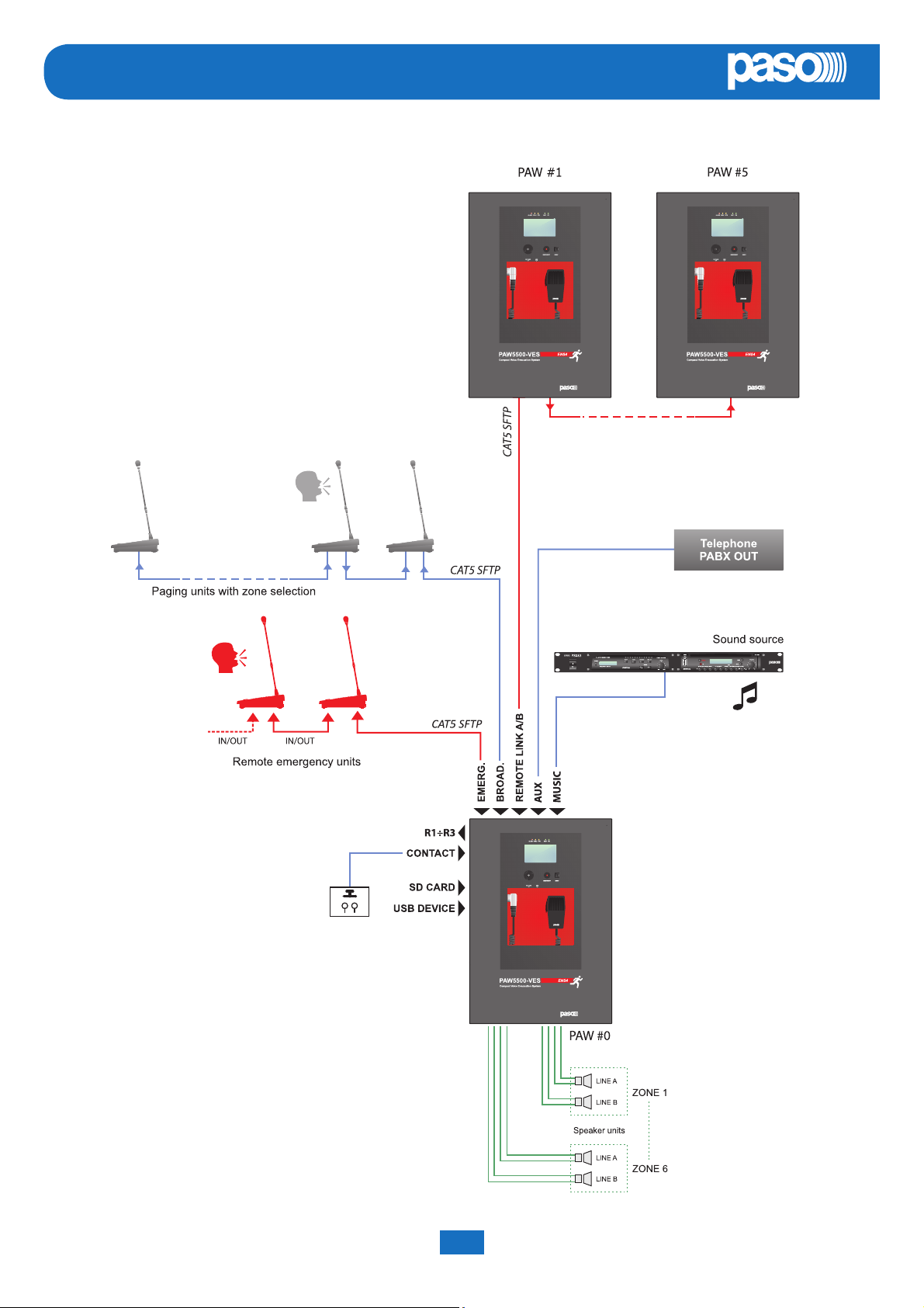
2.3 TYPICAL CONFIGURATION
PAW5500-VES
PAW5500-VES Compact systems System manual
6
Page 7
3. GENERAL DESCRIPTION
3.1 FRONT PANEL
PAW5500-VES
EN
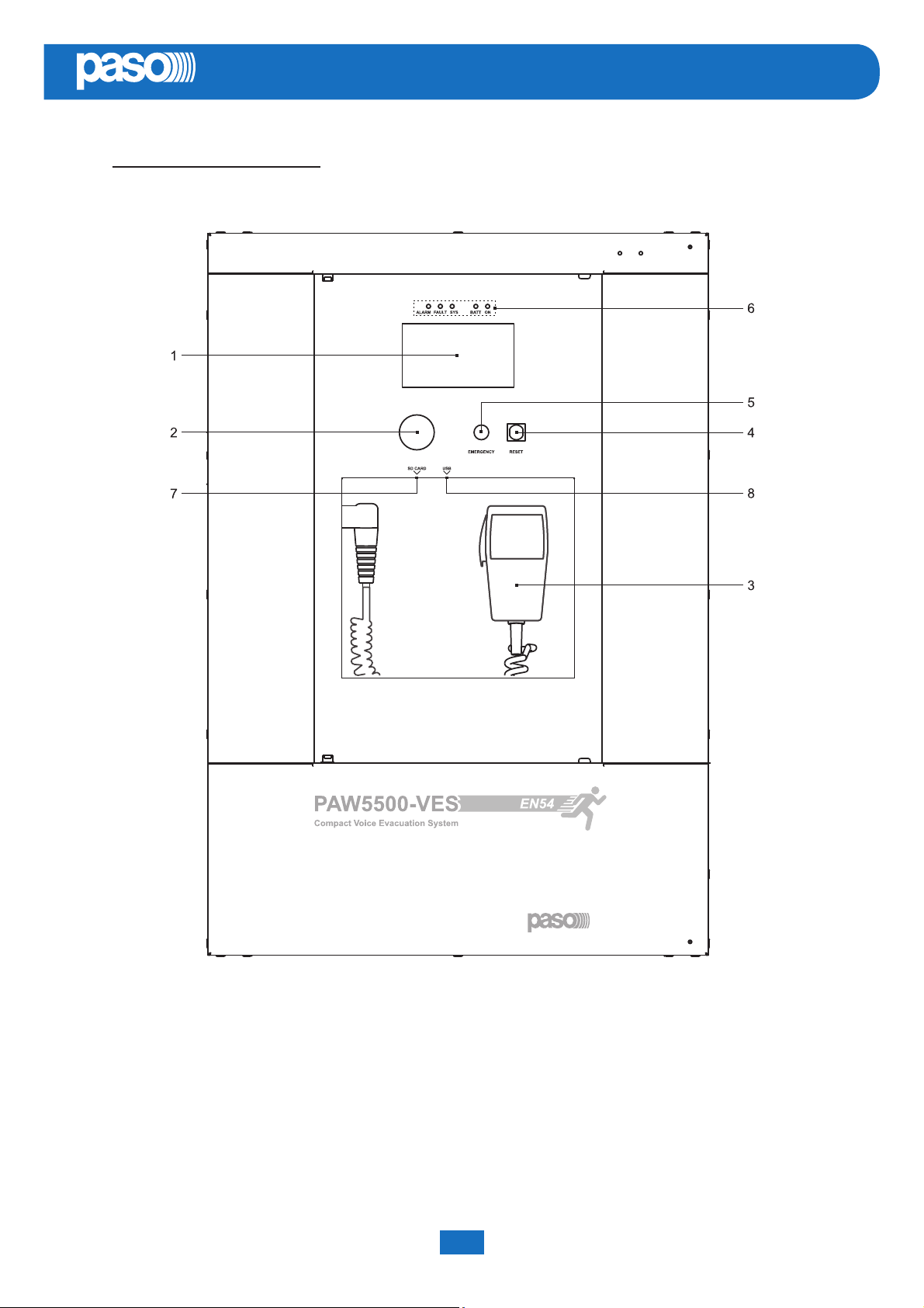
1) Backlit 4.3” display with touchscreen for selecting the Alert/Evacuation zones and for navigation for adjusting volume
levels, confi guring the equipment and viewing failures.
2) Integrated loudspeaker for playing back the output signals from the zones or the signals of the input sources and for
replaying the acoustic signal indicating that a failure has been detected (beep). The signalling tone will be automatically
muted if the conditions of failure end. Furthermore, in accordance with the regulations, the beep is muted by the system
while the Emergency Microphone is being used.
3) Handheld fi reman’s paging microphone.
4) RESET button.
5) EMERGENCY button.
6) Status LEDs.
7) SD card slot.
8) USB socket for external device.
System manual PAW5500-VES Compact systems
7
Page 8
EN
3.2 INSIDE VIEW
PAW5500-VES
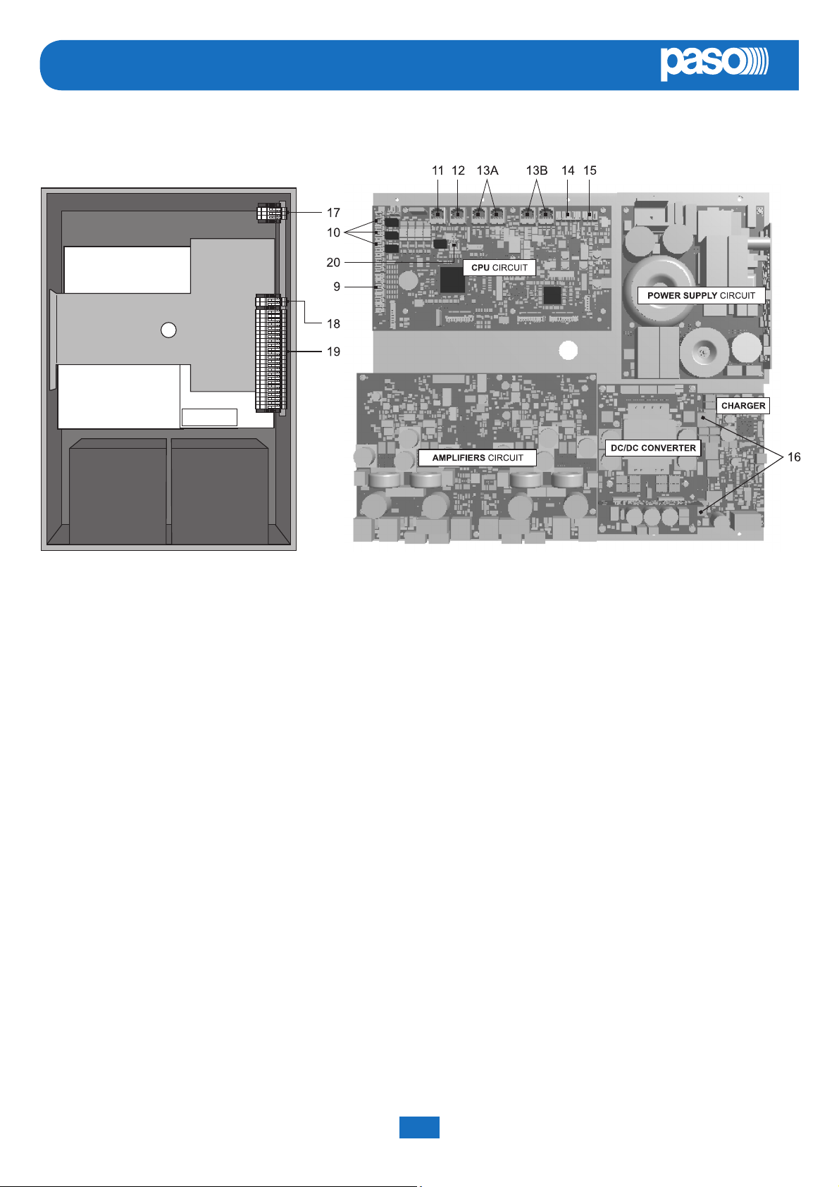
9) 7 off controlled input contacts.
10) 3 off relay output contacts.
11) Input for emergency microphone stations (max. 4).
12) Input for paging microphone stations (max. 16).
13) Input/output sockets REMOTE LINK A/B for connection to other PAW5500-VES units (overall max. of 6).
14) Input terminal strip for auxiliary sources with precedence contact.
15) Input terminal strip for music sources.
16) Connection to 24 VDC battery power.
17) Connection to 230 VAC power supply.
18) Connection of standby amplifi er.
19) Connection of loudspeakers lines.
20) Terminal strip for 21 to 29 V connection.
PAW5500-VES Compact systems System manual
8
Page 9
PAW5500-VES
EN
4. INSTALLATION AND CONNECTIONS
! N.B.
Please remind that the operations illustrated in this part of the manual must be carried out by specialised personnel
ONLY, trained and qualifi ed in the equipment installation and maintenance. When the PAW is opened, parts entailing
a high risk of electric shocks become accessible.
It is advisable to install the equipment in a closed and sheltered place, protected against possible sources of damage (rain,
moisture, high temperatures, etc.).
Depending on requirements, the cables can be inserted by eliminating either the plugs sealing the holes in the top or the rear
door (in both cases use a fl at screwdriver or a cutter to lift them and remove them).
! It is important to keep the power cables separate from those dedicated to the other connections.
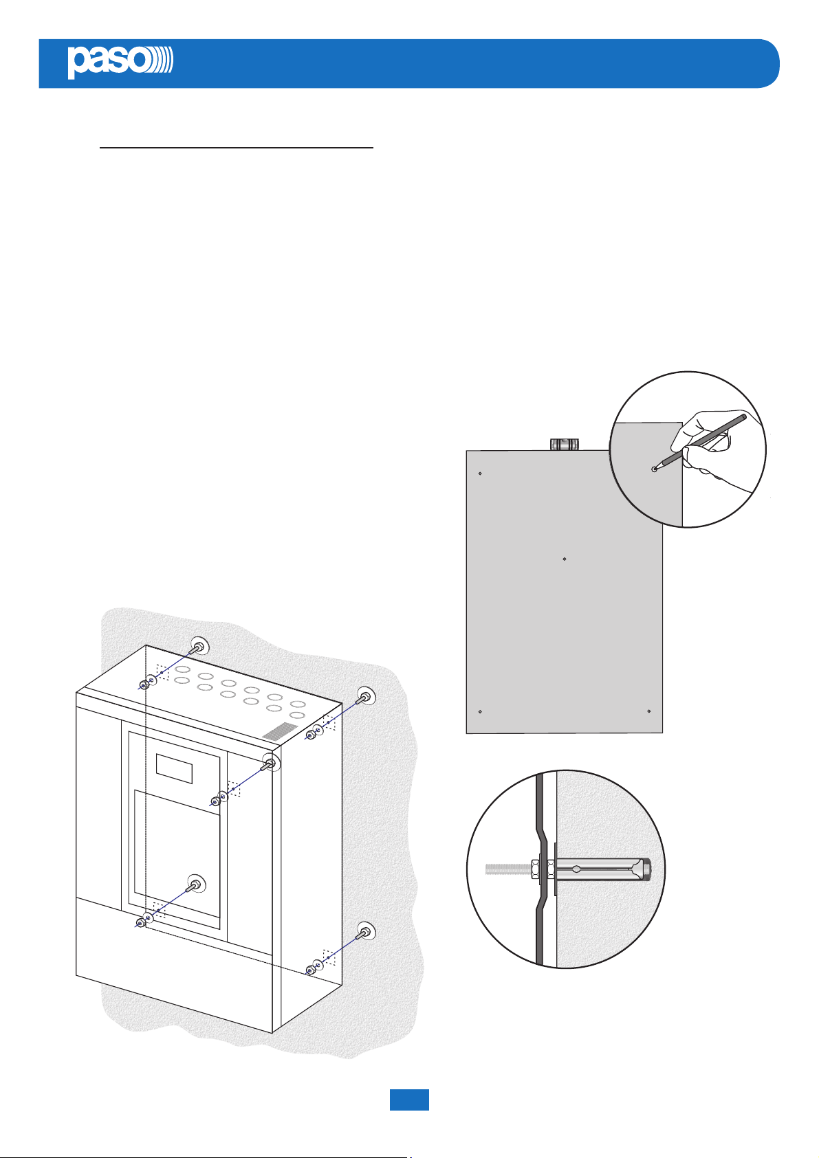
4.1 WALL MOUNTING
Take the cardboard template included in the package and position it
at a suitable height so that it is accessible to the user. Ideally, the front
display should be at eye level.
Having decided on the position, mark the fi ve points on the wall and fi t
Fischer wall plugs (min. Ø 9 mm) equipped with bolts into them.
Using the wall plugs as reference pins, lift the equipment and hook
it to the wall. It is advisable for this activity to be carried out by two
people.
Tighten the bolts.
NOTE:
For rack mounting, it is necessary to use the optional
accessory ACPAW-RCK and to follow the indications
provided on its instruction sheet.
System manual PAW5500-VES Compact systems
9
Page 10
EN
PAW5500-VES
4.2 CONNECTIONS
! N.B.
Check that the main thermal-magnetic circuit breaker is switched OFF.
If it is not, switch it OFF before carrying out any other activities in the cabinet as there is a danger of electric shocks.
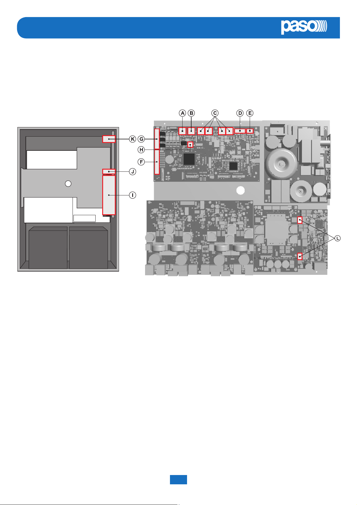
Proceed with connection of the various devices, referring to the appropriate points of the manual:
CPU circuit
A) Point 4.2.1 Connection of emergency units (page 11)
B) Point 4.2.2 Connection of paging units (page 11)
C) Point 4.2.3 Connection to other PAW5500-VES systems (page 12)
D) Point 4.2.4 Connection of auxiliary input (page 12)
E) Point 4.2.5 Connection of music input (page 13)
F) Point 4.2.6 Connection of input contacts (page 13)
G) Point 4.2.7 Connection of relay outputs (page 14)
(H) Point 4.2.8 21 to 29V connection (page 14)
AMPLIFIER circuit
H) Point 4.2.8 Connection of the loudspeaker lines (page 14)
I) Point 4.2.9 Connection of the standby amplifi er (page 15)
Once the basic connections have been made, it is possible to go on to connect the power supplies:
J/K) Point 4.2.10 Connection of power supplies (page 17)
! N.B.: It is essential to follow the correct sequence for powering up the equipment, failing which it could be
damaged.
PAW5500-VES Compact systems System manual
10
Page 11
PAW5500-VES
EN
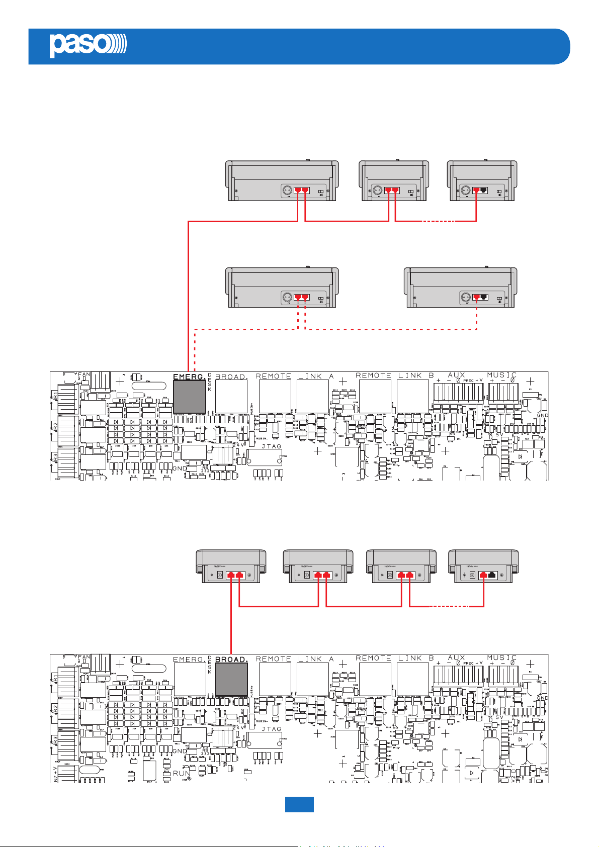
4.2.1 CONNECTION OF EMERGENCY UNITS CPU CIRCUIT
Use a CAT. 5e SF/UTP cable for connecting the EMERG. socket (11) to the ‘IN/OUT’ sockets of the PMB132 remote emergency
units (up to 4). As an alternative, it is possible to connect up to 2 touch screen units TSB8500-V. The length of the link between
the card-cage and the last station must not exceed 1000 metres at most.
PMB132/12-V
PMB132-V
PMB132-V
TSB8500-V
IN/OUTIN/OUT–+24V
#1
IN/OUTIN/OUT–+24V
#2
IN/OUTIN/OUT–+24V
#4
MAX 4 units
TSB8500-V
IN/OUTIN/OUT–+24V
#1
IN/OUTIN/OUT–+24V
#2
MAX 2 units
4.2.2 CONNECTION OF PAGING UNITS CPU CIRCUIT
Use a CAT. 5e SF/UTP cable for connecting the BROAD. socket (12) to the ‘IN/OUT’ sockets of the PMB106/112 paging units.
The length of the link between the card-cage and the last station must not exceed 1000 metres at most.
PMB112-G
1,5W MAX
+
-
IN/OUT IN/OUT SENS.
#1 #2
PMB106-G
1,5W MAX
IN/OUT IN/OUT SENS.
+
-
+
-
1,5W MAX
IN/OUT IN/OUT SENS.
#3 #16
1,5W MAX
IN/OUT IN/OUT SENS.
+
-
MAX 16 units
System manual PAW5500-VES Compact systems
11
Page 12
EN
PAW5500-VES
4.2.3 CONNECTION TO OTHER PAW5500VES UNITS CPU CIRCUIT
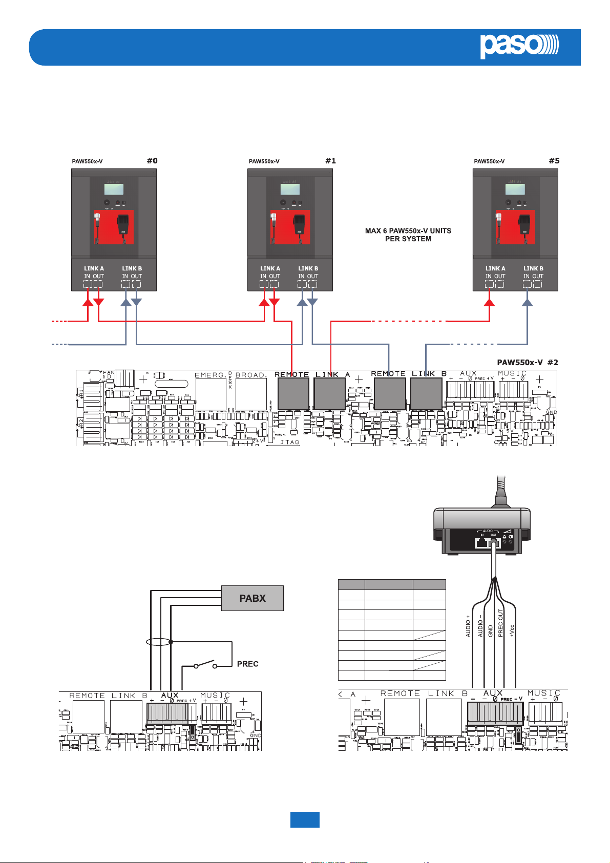
Use CAT. 5e SF/UTP cables for connecting other PAW5500-VES units (up to a maximum total of 6 per system) via the
REMOTE LINK A/B sockets (13). The length of the link between the fi rst card-cage and the last unit must not exceed 1000
metres at most.
4.2.4 CONNECTION OF AUXILIARY INPUT CPU CIRCUIT
The AUX terminals (14) are available for connecting auxiliary sources (e.g. a PABX
or a base for announcements with a precedence contact). In the fi rst case, to which
Fig. 1 refers, it is necessary to fi t a jumper onto connector CN9 in position “P-”. In the
second case, on the other hand, using a pre-amplifi ed station of the B711-G range,
connection between the AUDIO OUT socket of the base and the AUX terminals has
to be made as indicated in Table 1 and the jumper will have to be positioned on “P+”.
NOTE: Selection between modes P- and P+ must be made also via the menu (AUDIO
SETTING > set>AUX, CHIME, page 27).
Pin Base AUDIO OUT PAW AUX
1 Audio + +
2 Audio – –
3 GND 0
4 Precedence OUT PREC
5 Not connected
6 +VDC +V
7 Serial +
Fig. 1 Fig. 2
8 Serial –
Shield GND 0
For details concerning connection and the colours of the wires, refer to the manual of the B711-G base range
(Paso # 11/636-B).
PAW5500-VES Compact systems System manual
12
Page 13
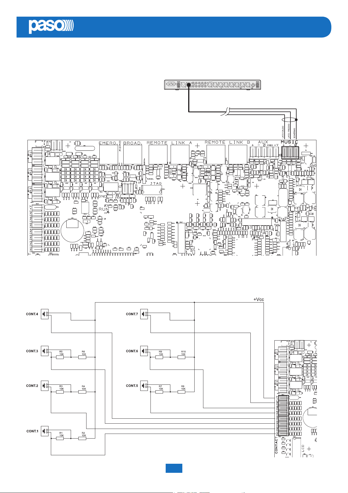
PAW5500-VES
4.2.5 CONNECTION OF MUSIC INPUT CPU CIRCUIT
The MUSIC terminals (15) are available for connecting outside music sources (CD player, tuner etc.).
EN
4.2.6 CONNECTION OF INPUT CONTACTS CPU CIRCUIT
There are 7 input contacts on the CONTACT terminal strip (9): the fi gure shows an example of a connection in which contacts
1, 2, 3, 5 and 6 are of the monitored type while contacts 4 and 7 are not.
System manual PAW5500-VES Compact systems
13
Page 14
EN
PAW5500-VES
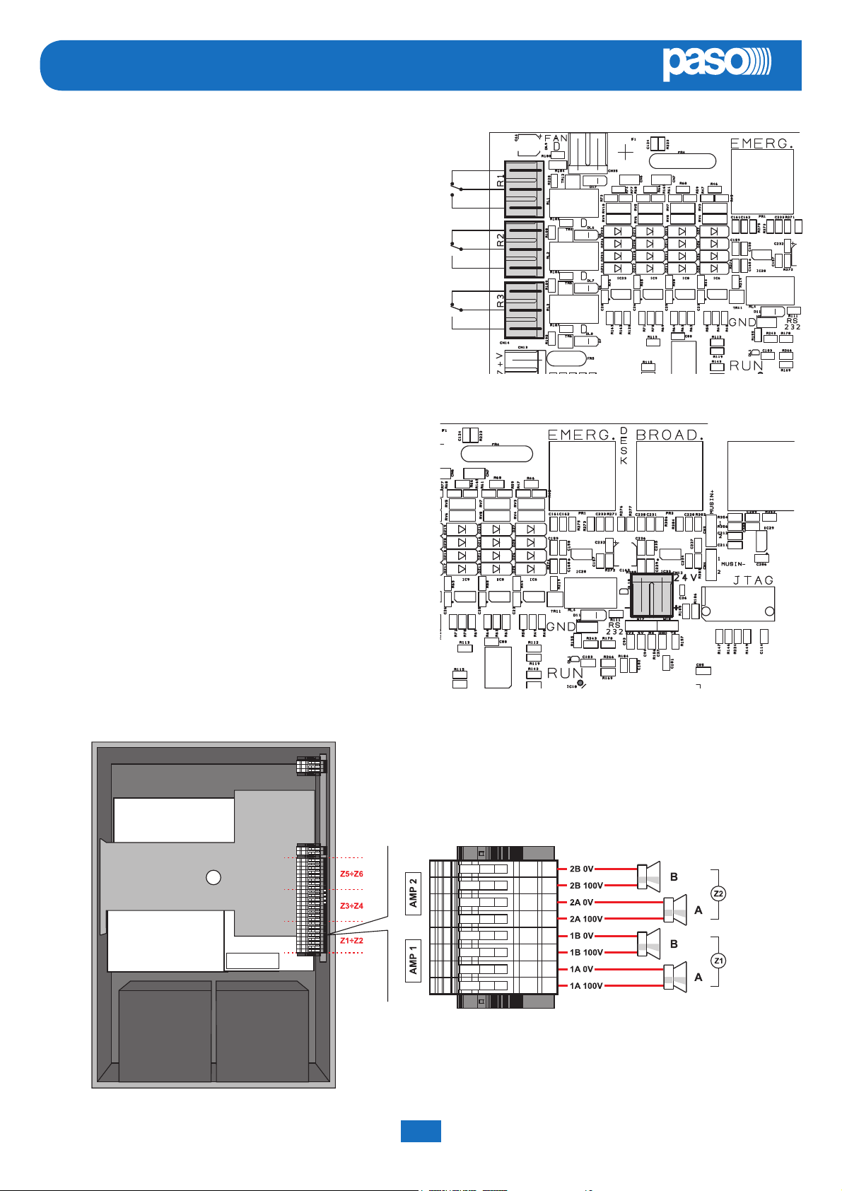
4.2.7 CONNECTION OF RELAY OUTPUTS CPU CIRCUIT
Three relay outputs are available on terminals R1, R2 and R3
(10) for signalling towards outside peripheral units.
4.2.8 21 TO 29 V CONNECTION CPU CIRCUIT
Depending on how the PAW will be working, it is possible to
receive a 21 to 24V power supply on the 24V terminals (20),
with a maximum absorption of 50 mA.
4.2.9 CONNECTION OF LOUDSPEAKER LINES
AMPLIFIERS CIRCUIT / TERMINAL STRIP
Terminals A/B (19) are dedicated terminals for connection of the
loudspeaker lines. The wiring of a PAW5502-V model (2 zones) is
shown in the fi gure below.
PAW5502-V
PAW5500-VES Compact systems System manual
14
Page 15
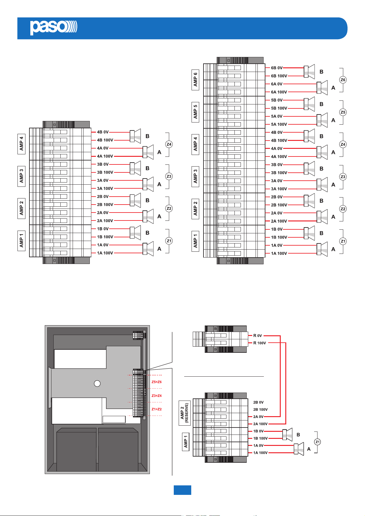
PAW5500-VES
The connections for 4 and 6 zone models (respectevely
PAW5504-V and PAW5506-V) are shown in this fi gure.
EN
PAW5504-V PAW5506-V
4.2.10 CONNECTION OF THE STANDBY AMPLIFIER TERMINAL STRIP
Using both terminal strip R (18) and A/B (19) it is possible to set a standby amplifer: here’s the connection of a PAW5502-V model
(1 zone + standby amplifi er). In the following pages, the connections for PAW5504-V model (3 zones + standby amp) and
PAW5506-V (5 zones + standby amp).
1ZONE SYSTEM + STANDBY
PAW5502-V
System manual PAW5500-VES Compact systems
15
Page 16
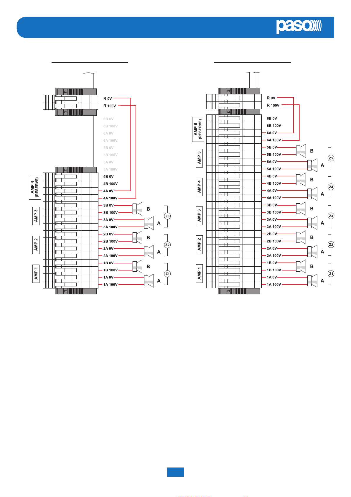
EN
PAW5500-VES
3ZONE SYSTEM + STANDBY 5ZONE SYSTEM + STANDBY
PAW5504-V PAW5506-V
PAW5500-VES Compact systems System manual
16
Page 17
PAW5500-VES
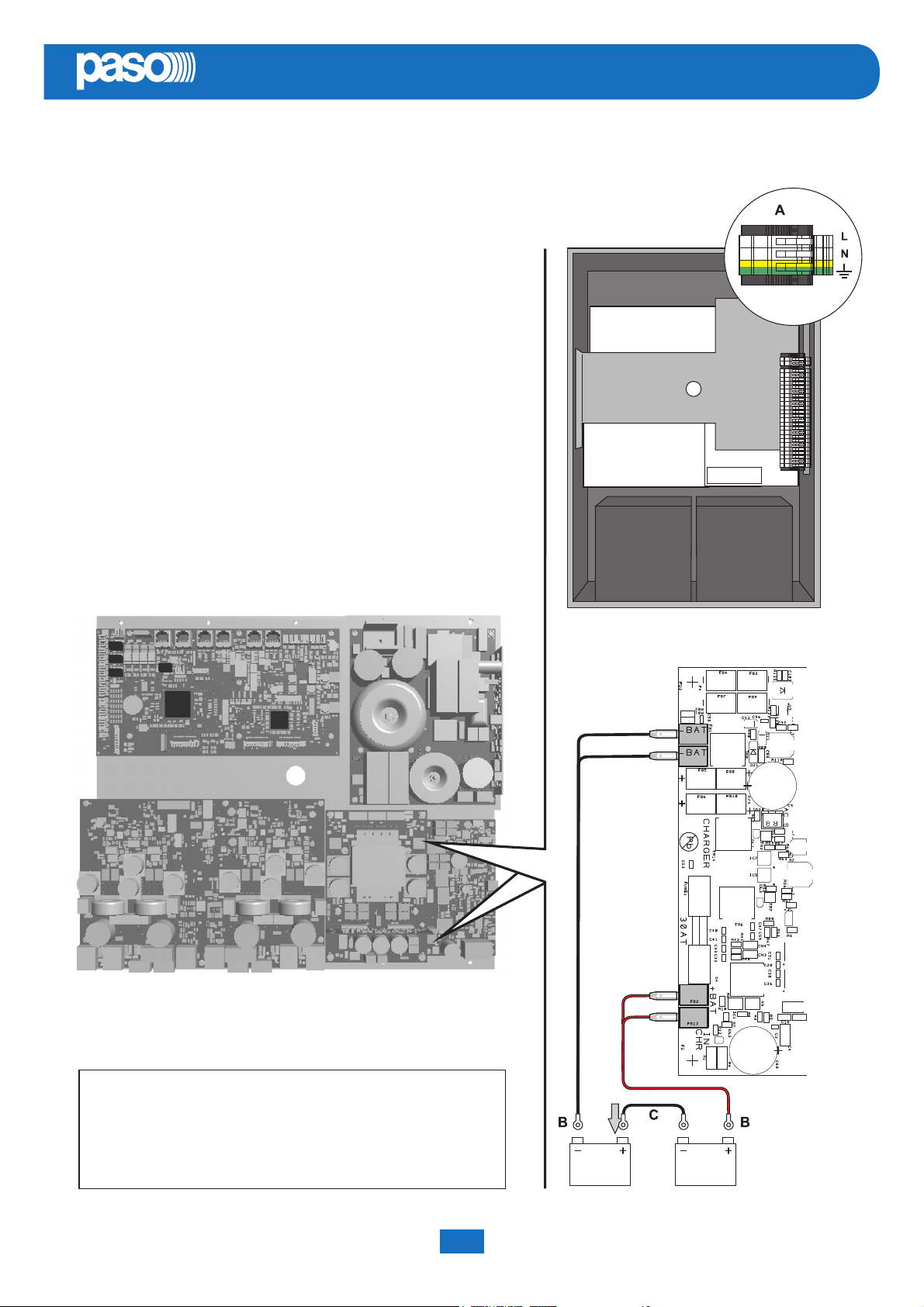
4.2.11 CONNECTION OF POWER SUPPLIES TERMINAL STRIP AND CHARGER
!N.B.
Check that the main thermal-magnetic circuit breaker is switched
OFF. If it is not, switch it OFF before carrying out any other activities
in the cabinet as there is a danger of electric shocks.
!N.B.
These devices have been designed to be connected to an earthed
power supply. Make sure that the equipment is always connected
to earth in accordance with legal regulations.
It is essential to follow the correct sequence for powering up the
equipment, failing which it could be damaged.
1> Check that the main thermal-magnetic circuit breaker is switched
OFF.
2> Connect the power cable coming from the thermal-magnetic circuit
breaker and the earth cable to the contacts on the terminal strip
(A) - see fi gure.
3> Connect the external terminals (B) of the batteries,
observing the correct polarities.
4> Switch the thermal-magnetic circuit breaker ON.
EN
5> Make a jumper between the inside terminals of the
batteries using the cable (C) included in the supply.
6> Close the front door, tightening the screws fi rmly.
From now on the PAW is working.
NOTE:
If the front door is opened, the amplifi ers are deactivated
automatically, and can be re-activated by specialised
personnel only by using a specifi c menu item.
System manual PAW5500-VES Compact systems
17
Page 18

EN
PAW5500-VES
5. OPERATIONAL CONDITIONS AND TERMINOLOGY
Following is a list of how the operating conditions of the system are signalled and of the defi nitions used on the subsequent
pages of the manual, completed by indications of a general nature.
5.1 SIGNALLING OF OPERATING CONDITIONS
The PAW is designed to signal the diff erent operating conditions as defi ned below:
Idle state (ALARM, FAULT and SYS LEDs off )
Normal operating condition, with no current faults or emergencies.
Alarm Status (ALARM LED on)
Operating condition signalling the presence of at least one alarm signal, either pre-recorded or live, in at least one output zone.
Faulty status (FAULT LED on)
Operating condition signalling the presence of at least one fault detected by the internal diagnostic system, with the relevant
LED turning on.
System failure (SYS LED on)
Operating condition signalling that the system has crashed due to temporary or permanent CPU malfunctioning, detected by
the watchdog device.
Automatic Emergency (Display showing ‘AUTOMATIC EMERGENCY’ with active zones)
Sequence of operations recalled by an external peripheral unit connected to the control inputs that, depending on how these
are programmed, activates the Alarm Status or resets the alarms.
Manual Emergency (LED of the EMERGENCY button steady ON or fl ashing)
Procedure of action on the system manual controls by an authorised operator, in order to activate emergency sources.
Operations in the Manual Emergency mode have priority over those activated in the Automatic Emergency mode.
6. DEFINITIONS
BGM source (Background Music)
One of the audio sources that can occupy the “Music” amplifi cation channel.
PA source (Public Address)
One of the audio sources that can occupy the “Voice” amplifi cation channel for service announcements.
Emergency Source
One of the audio sources that can occupy the “Voice” and/or “Music” channels for voice emergency announcements (prerecorded messages announcing an Alert and/or Evacuation, live messages from the local microphone, a call from a remote
emergency microphone station). Activation of an Emergency Source generates the operational condition of “State of Alarm”.
Priority
Occupation of the output zones by an audio signal or a reset order is governed hierarchically by the priority level assigned to
each active source. The current activation of the area can be stopped only by another with a higher priority.
PAW5500-VES Compact systems System manual
18
Page 19
PAW5500-VES
EN
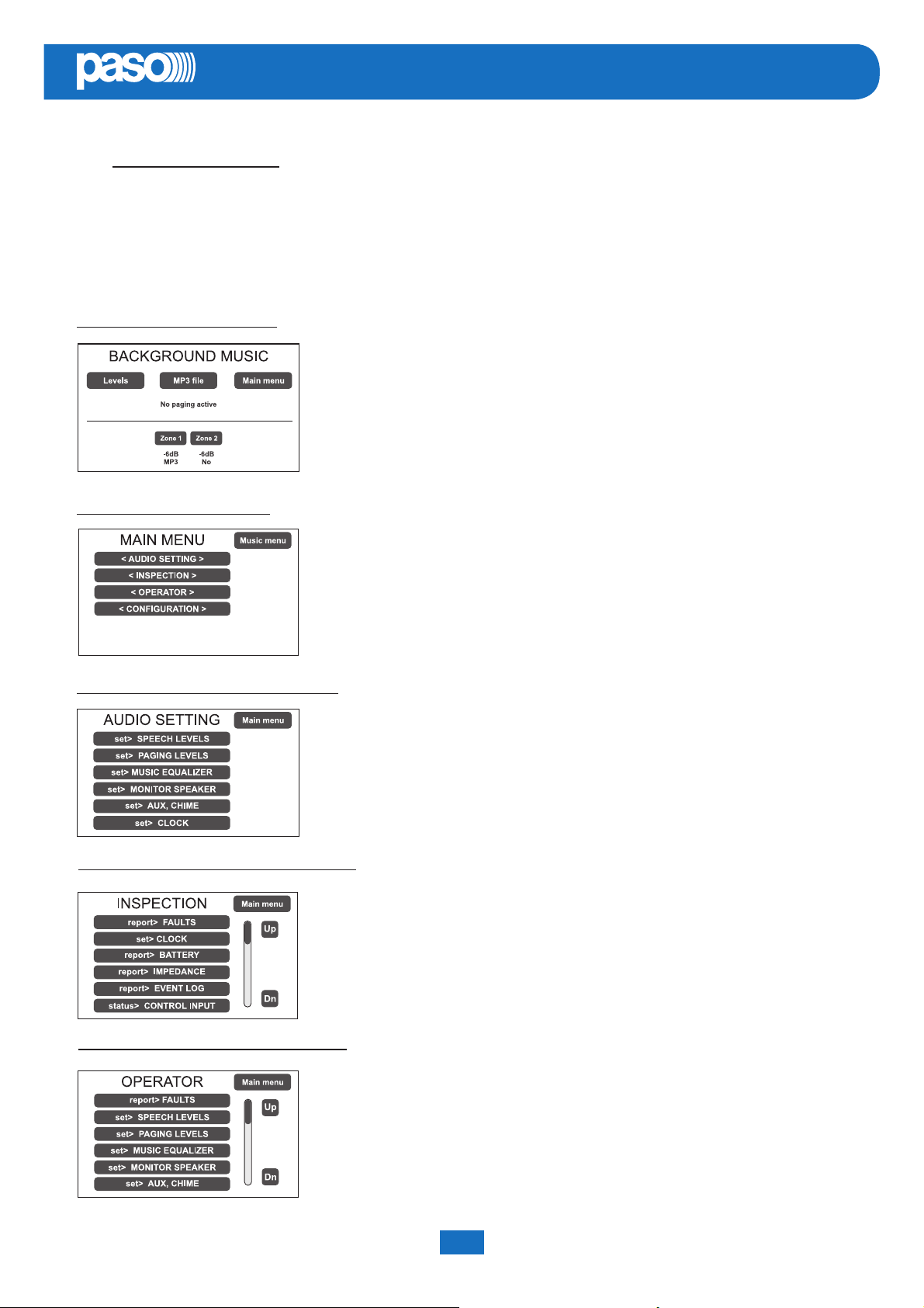
7. MENU STRUCTURE
The PAW allows system functions to be accessed through a series of Management Panels grouped, according to their
operational typology and intended use, in Option Menus accessible from the MAIN MENU window. Furthermore, the following
Option Menus have been assigned to diff erent levels of access, with reference to the various circumstances requiring diff erent
degrees of skill and authorisation of the personnel assigned. In each menu it is possible to browse through the options listed by
running a fi nger over the sidebar or pressing the ‘Up’ and ‘Dn’ (Down) buttons. To select an item, press the appropriate button.
Similarly, the levels can be adjusted simply by moving the cursor along the indicator bar.
<MUSIC> MENU | BASE LEVEL
Default window for using the system in normal Idle State conditions, enabling controlling
of the BGM (Background Music) sources, the selection of MP3 fi les from external
devices (an SD card or a USB key) and adjustment of the volumes of the music section.
At this basic level, the RESET button is not operational.
This panel is shown immediately when the system is switched ON.
To access the Main Menu press the ‘Main Menu’ button.
For the specifi c features of the MUSIC menu, see page 25.
<MAIN> MENU | BASE LEVEL
Main menu for selecting the four PAW operational levels.
At this basic level the RESET button is not operational.
To go back to the MUSIC Menu press the ‘Music Menu’ button.
To select the required item press the relevant key.
<AUDIO SETTING> MENU | BASE LEVEL
From the MAIN MENU screen, press the < AUDIO SETTING > key to access this menu.
To select the required item press the relevant key.
To return to the main screen press ‘Escape’.
For the specifi c features of the AUDIO SETTING menu, see page 26.
<INSPECTION> MENU | 1 SYSTEM LEVEL
ST
First level of access, for inspecting the state of the system.
This is intended for the personnel responsible for initial checking of the causes of a
fault or emergency. At this level the function of the RESET button is that of muting the
acoustic signal indicating the FAULT.
To select the required item press the relevant key.
To go back to the main menu Press ‘Main menu’.
For the specifi c features of the menu INSPECTION, see page 29.
<OPERATOR> MENU | 2 SYSTEM LEVEL
System manual PAW5500-VES Compact systems
ND
Second level of access, for instructed personnel authorised to manage the system in
emergency, failure and disabled conditions.
The relevant login password must be entered to access this menu.
To go back to the main screen press ‘Main menu’.
For the specifi c features of the OPERATOR menu, see page 32.
19
Page 20
EN
PAW5500-VES
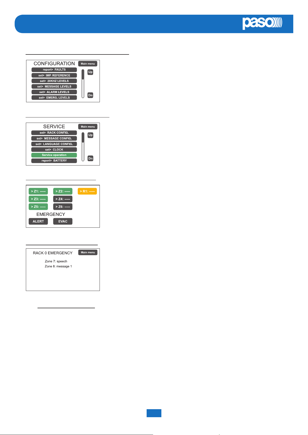
<CONFIGURATION> MENU | 3 SYSTEM LEVEL
<SERVICE> MENU | 4 SYSTEM LEVEL
TH
RD
Third level of access, for instructed personnel authorised to work on the advanced
functions of the system and to alter the confi guration parameters, for starting up and
altering the system. The relevant login password must be entered to access this menu.
To go back to the main screen press ‘Main menu’.
For the specifi c features of the CONFIGURATION menu, see page 35.
Fourth level of access, included among the options of the CONFIGURATION menu,
for technical assistance, fi rmware up-dating and altering the PAW system operating
parameters. Use is permitted only to personnel of the technical service who have the
necessary login password.
To go back to the main screen press ‘Main menu’.
<EMERGENCY> MENU | ACTIVE
Operational environment for managing Manual Emergencies with top priority.
Accessible at all times with the dedicated “EMERGENCY” key, it can be used by
authorised personnel only, suitably instructed with regard to the Emergency and
Evacuation Plan (PEE).
For the specifi c features of the EMERGENCY menu, see page 44.
<EMERGENCY> MENU | PASSIVE
This window appears automatically and shows the card-cage emergency status
called up from emergency microphone stations, control inputs or other card-cages.
It is possible to access the other menus (except for the music menu) by pressing
‘Main menu’.
8. USING THE SYSTEM
After making all the connections and supplying power to the card-cage, observing the indications provided in the relevant
chapter, and once the door of the cabinet has been closed, the display lights up and shows the panel of the MUSIC Menu, from
which it is possible, by pressing the ‘Main Menu’ key, to access the main screen for selecting the menus.
If the system is being used for the fi rst time, or if changes have been made to its confi guration, proceed as indicated in the
CONFIGURATION OF THE SYSTEM section. If, on the other hand, the initialisation procedure has already been completed,
continue with the indications for use as provided below.
• For normal use for broadcasting music and microphone announcements, users may limit their activities to the MUSIC
and AUDIO SETTING menus.
• For management in faulty/emergency conditions and for confi guration using advanced functions, see the INSPECTION,
OPERATOR and CONFIGURATION menus.
• For sending emergency messages, see the MANUAL EMERGENCY section.
PAW5500-VES Compact systems System manual
20
Page 21
PAW5500-VES
EN
8.1 CONFIGURATION OF THE SYSTEM
Confi guration activities may be carried out only by qualifi ed personnel, suitably trained for this purpose.
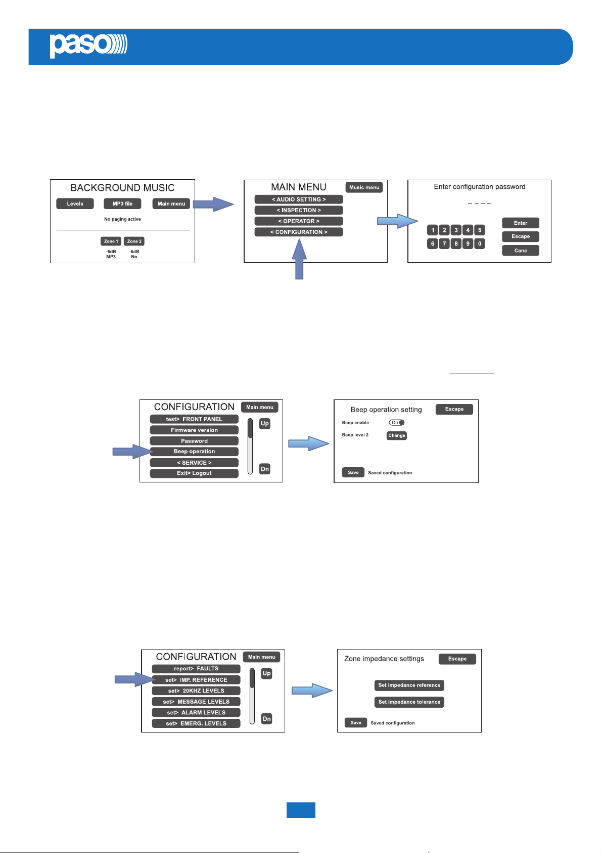
A) Password
From the MUSIC MENU, go to the MAIN MENU and select < CONFIGURATION >. If access only with a password is
enabled, ‘Enter confi guration password’ will appear on the screen.
Enter the 4-digit code of the password and confi rm by pressing ‘Enter’ (the factory default password is 3333; see page 35).
B) Muting the BEEP
During the initialisation process, it is possible that faults may be detected due to diff erences between the confi guration of
the system being connected and the values set by default. To mute the acoustic signal (beep) temporarily, browse down
through the CONFIGURATION menu and select the item ‘Beep operation’.
In the ‘Beep operation setting’ window, move the ‘Beep enable’ slider to ‘Off ’.
Press ‘Save’ to save this setting.
! N.B.
In order to comply with regulations, before returning the equipment to its normal operation it is necessary to
enable the acoustic signalling by returning the ‘Beep enable’ slider to its ‘On’ position.
C) Acquisition of impedances
From the CONFIGURATION menu, select the item ‘set> IMP. REFERENCE’ to access the ‘Zone reference setting’
screen page.
From here it is possible to set the reference impedance and the tolerance for controlling the impedance of the loudspeaker
lines (refer to the point on Acquisition of impedance and setting of tolerance on page 36).
System manual PAW5500-VES Compact systems
21
Page 22
EN
D) Rack confi guration
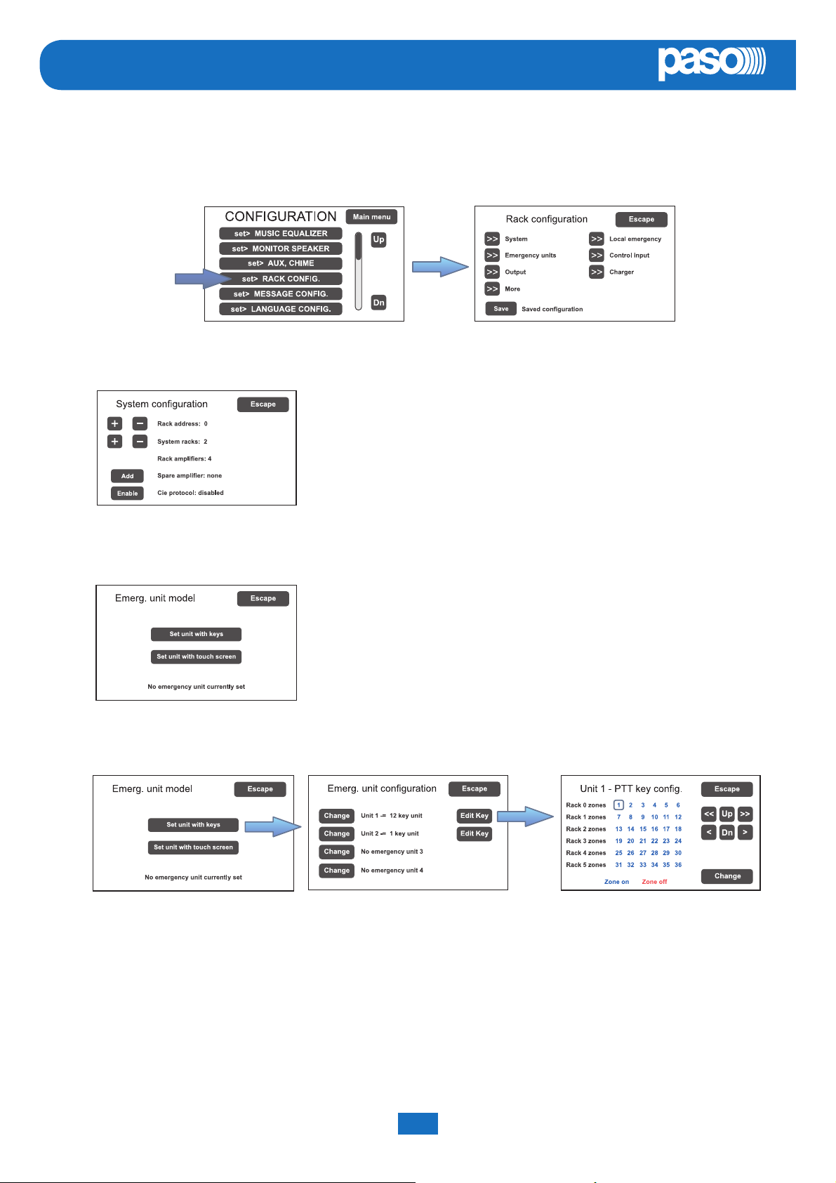
In the CONFIGURATION menu, browse through the items and select ‘set>RACK CONFIG’.
From here it is possible to confi gure all the basic settings of the system.
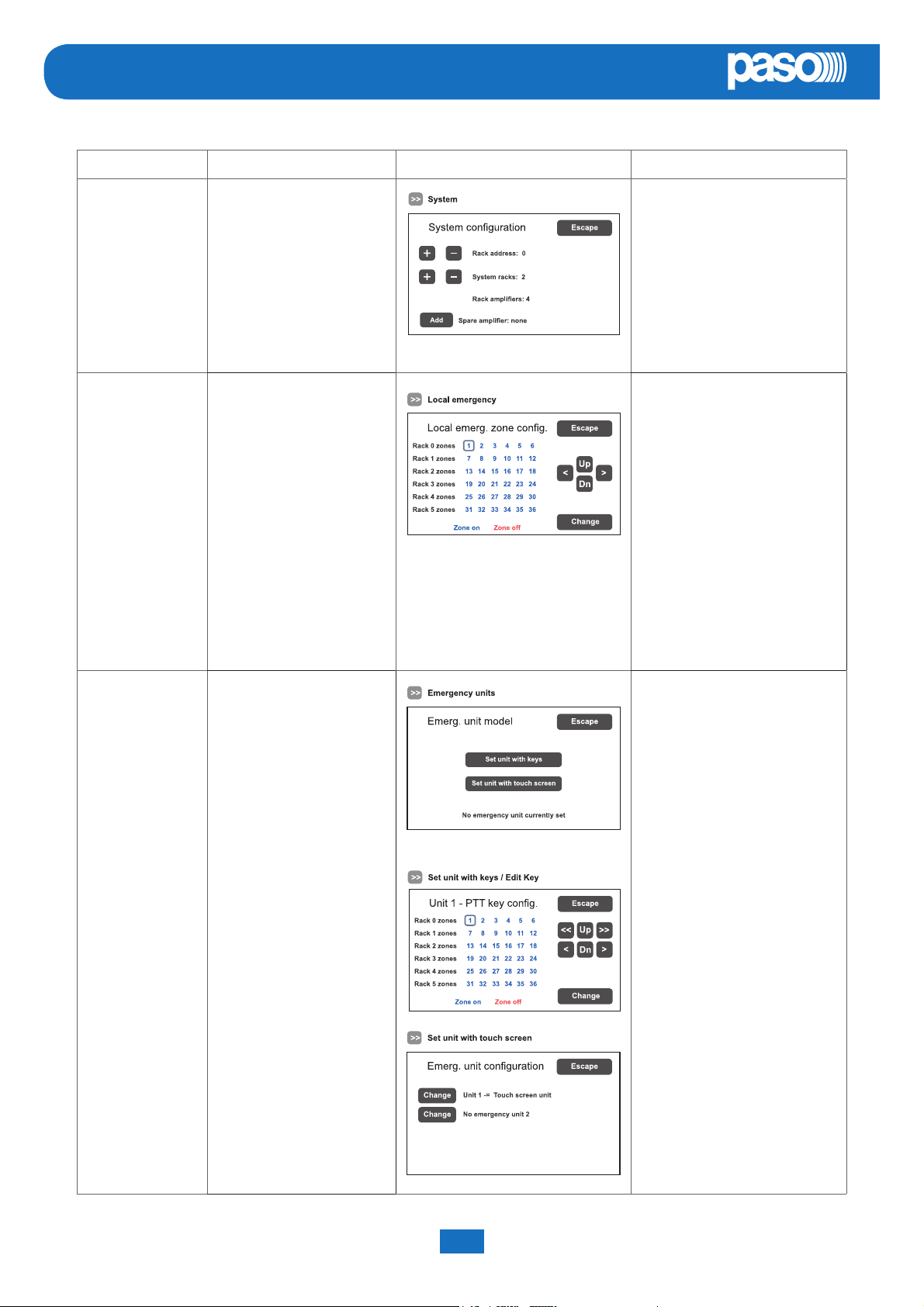
D1) >> System
On the ‘System confi guration’ screen page, use the [ + ] and [ – ] keys to set the
following:
Rack address: ID address of the PAW (from 0 to 5).
System racks: number of PAWs present in the system (6 at most).
Spare amplifi ers: standby amplifi er (add or remove).
The item ‘Rack amplifi ers’ automatically shows the number of amplifi ers present in
the system.
PAW5500-VES
D2) >> Emergency units
On the ‘Emerg. unit model’ screen page, use the sub-menus to set the
confi guration of the emergency units.
Set unit with keys Confi guration of the keys of the stations
In an emergency system with PAW5500-VES control units, it is possible to connect up to four remote emergency units:
click on ‘Change’ to set the unit type:
1 key unit = single zone unit (PMB132-V)
12 key unit = 12-zone unit (PMB132/12-V)
Then press ‘Edit Key’ to confi gure each key (see Emergency units on page 38).
By pressing ‘Set unit with touch screen’, the screen page on which it is possible to confi rm the presence or otherwise of
TSB8500-V stations connected to the PAW will appear.
PAW5500-VES Compact systems System manual
22
Page 23
PAW5500-VES
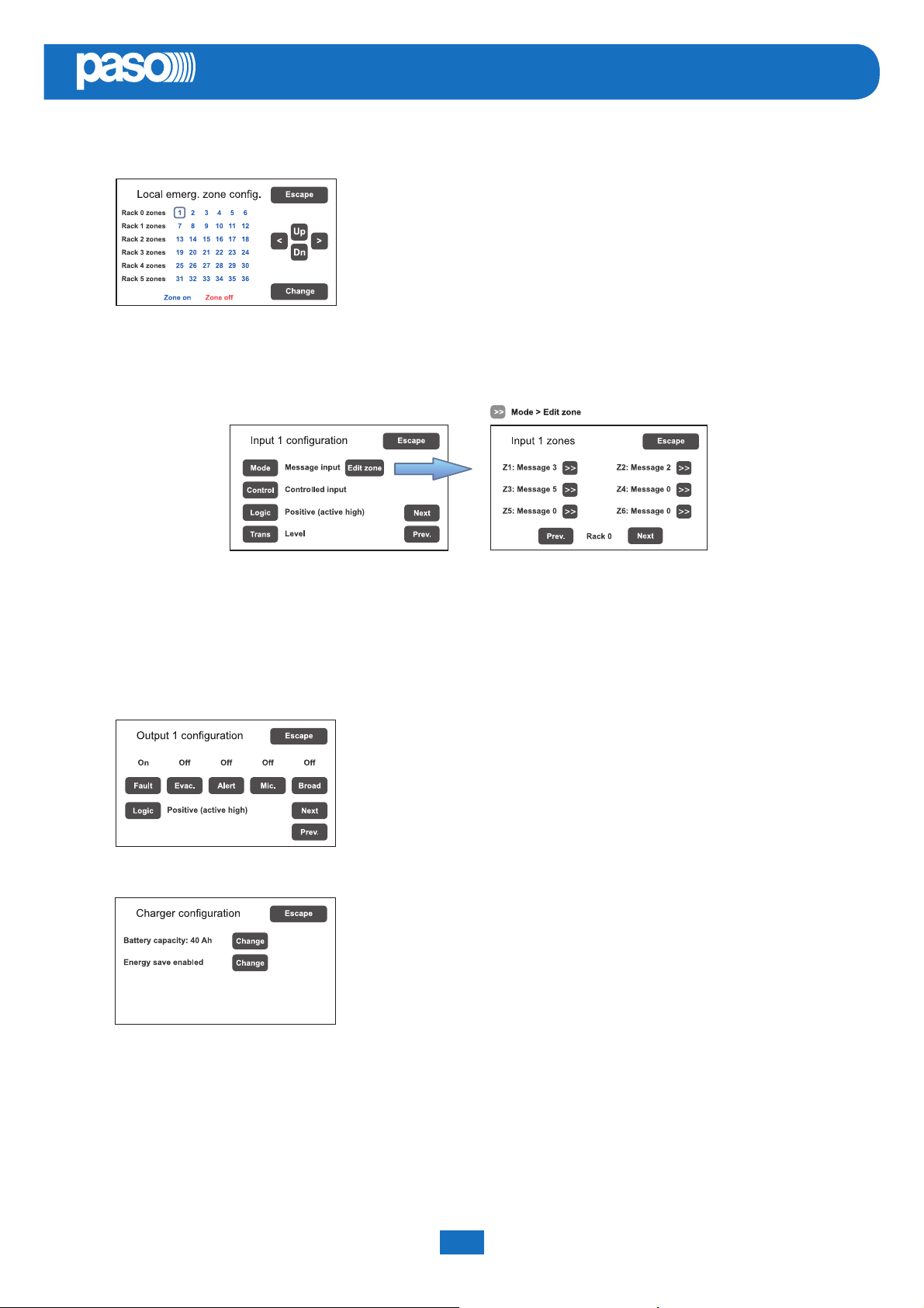
D3) >> Local emergency
Screen page for setting the zones in which the emergency messages will be
broadcast. The panel shows the situations of all the PAWs present in the system.
Move in the table using the arrows and the Up and Dn keys.
The zones selected in this window are called up directly on pressing the EVAC /
ALERT / PTT keys if no selections are made in the emergency menu.
Blue = Active zone / Red = Inactive zone
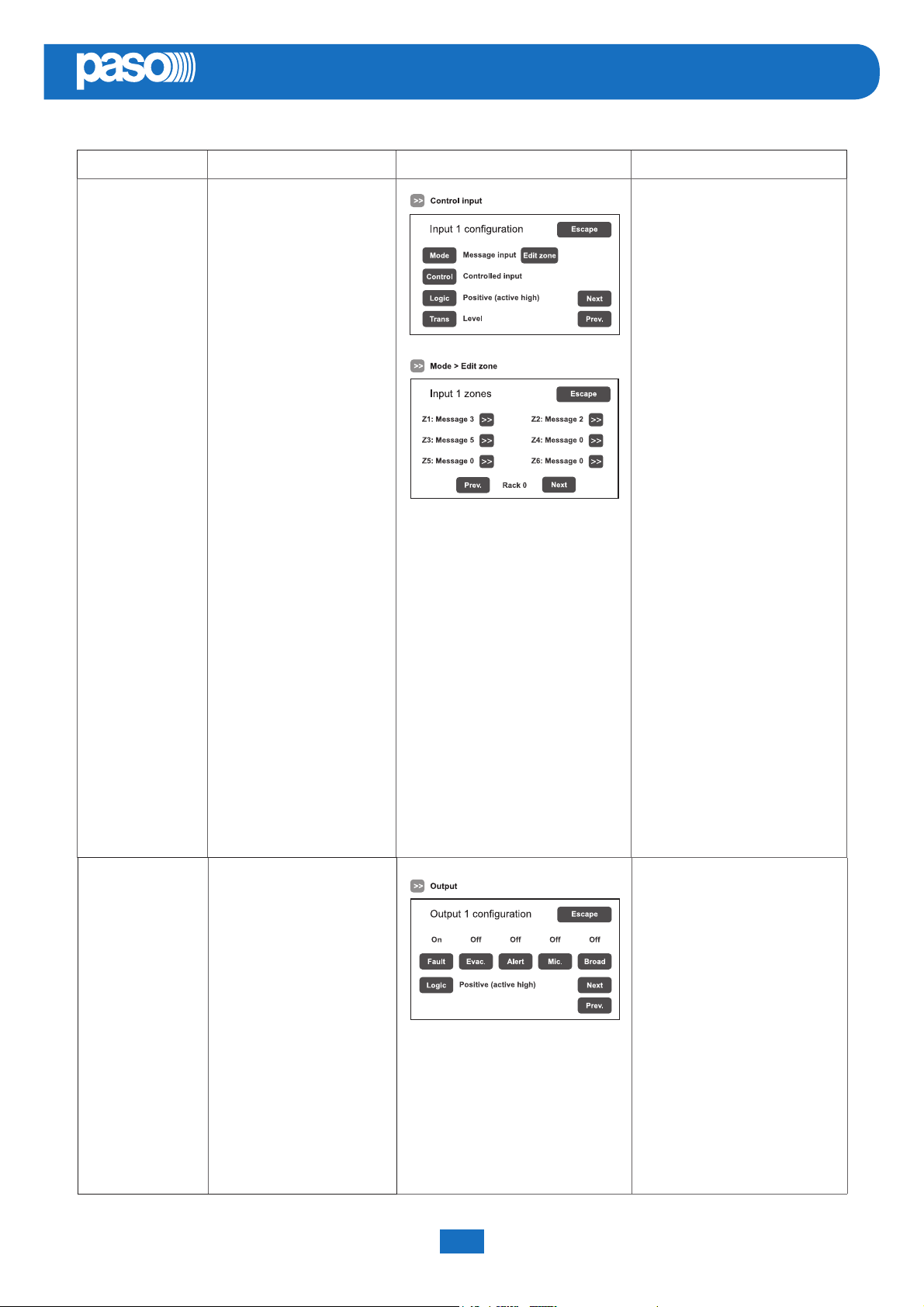
D4) >> Control input
Screen page for managing the inputs being controlled (1 to 7).
Use the ‘Next’ and ’Prev.’ Keys to move from one input to another.
EN
Mode Setting of the operating mode of the input (message, reset or de-activated) and of the relevant zones
(only if the item “Message input” is selected).
Control Enabling/disabling of control of the selected input.
Logic Setting of the logic for input activation.
Trans Enabling of the level or transition input.
D5) >> Output
Screen page for setting the outputs (1 to 3).
Use the ‘Next’ and’Prev.’keys to move from one output to another.
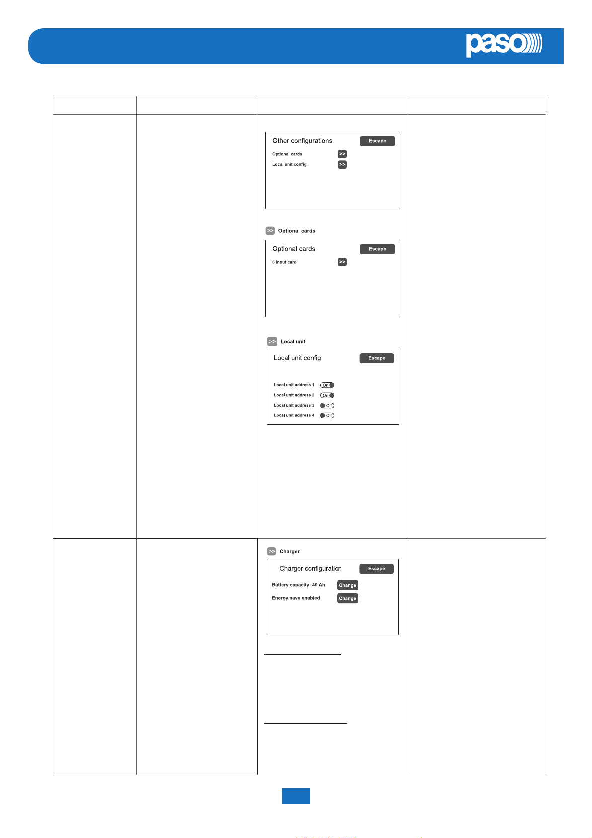
D6) >> Charger
On selecting the item >>Charger this screen page containing information about
the internal batteries appears.
Battery capacity
Press ‘Change’ to select a value: 18, 26, 33 or 40 Ah. Please see page 40 for details.
Energy save (enabled/disabled)
For enabling/disabling the function allowing the batteries to go into the energy saving mode in the absence of the
mains power supply.
! N.B. In order to comply with the regulations, the “Energy save” function should always be enabled.
System manual PAW5500-VES Compact systems
23
Page 24
EN
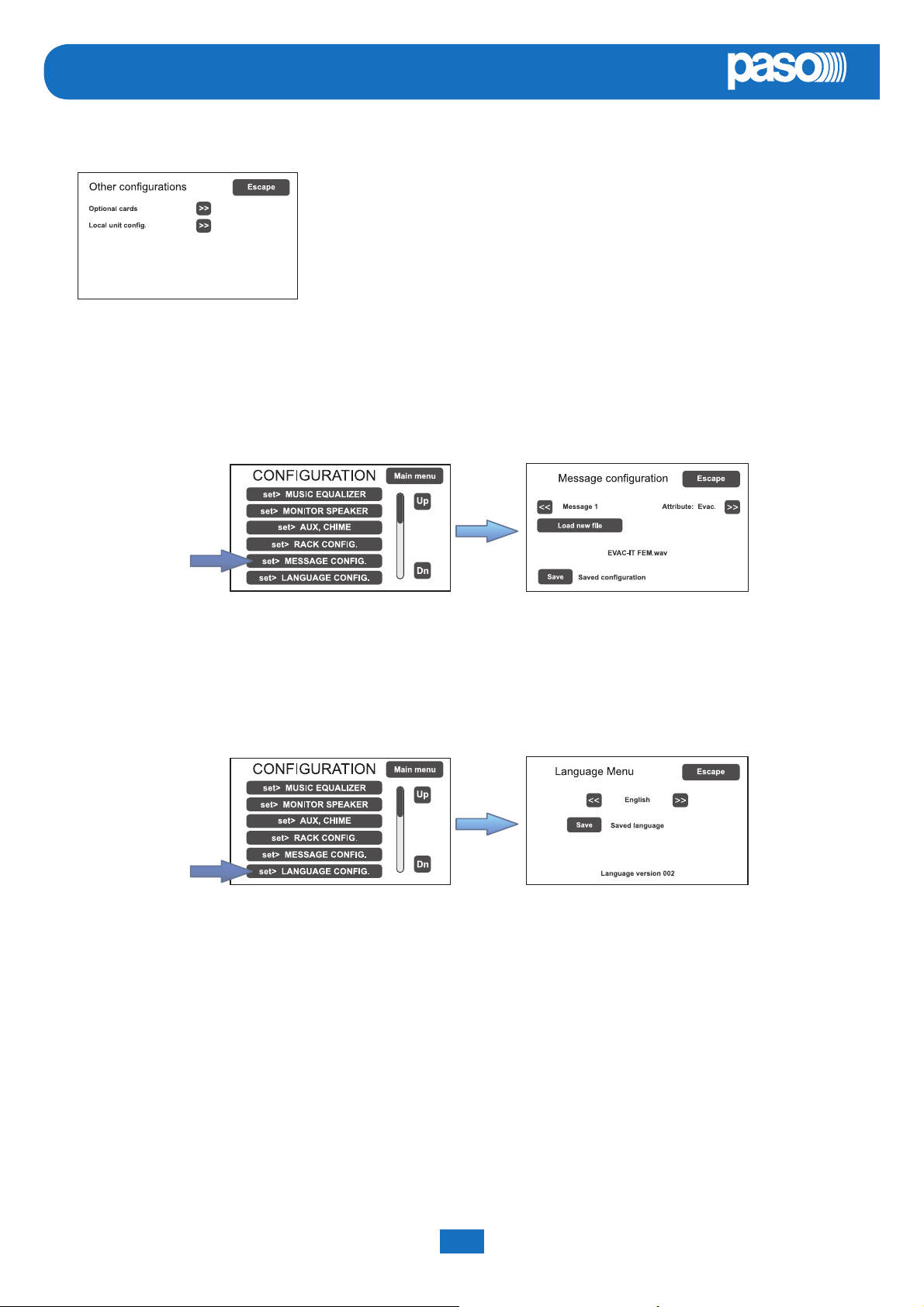
D7) >> More
On selecting the item >>More, this screen page appears, enabling the selection of:
- Broadcasting stations to be set as local. On activating this function, keys 1 to 6
of the station will correspond, in the same order, to the zones of the card-cage to
which the station itself is connected (e.g. if the local base is connected to card-cage
2, key 1 will correspond to zone 13, key 2 to zone 14 and so on). It is advisable to
use Paso PMB106-G units as local stations.
- Selection of an optional card, if any, present in the system (ACPAW-2IN or
ACPAW-6IN).
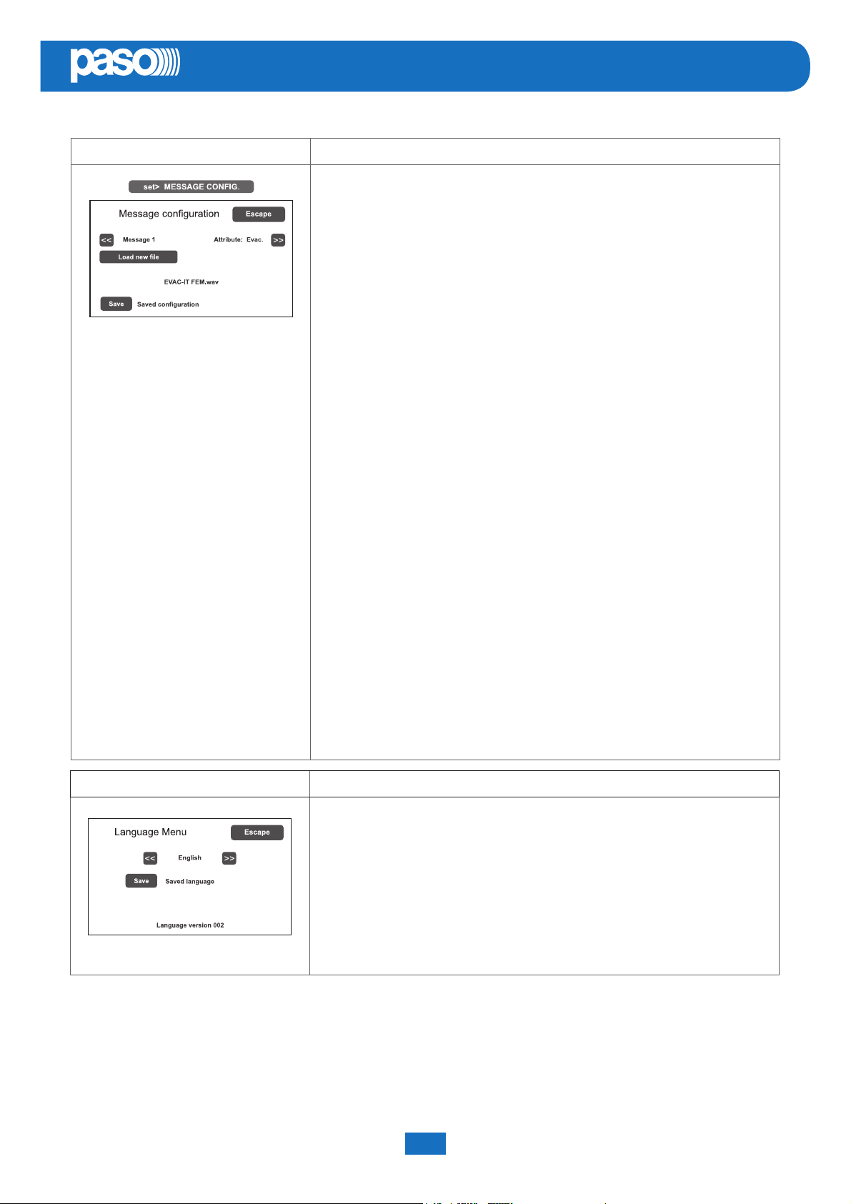
E) Emergency messages
The default messages (alert, evacuation and warning signal) are stored in the PAW5500-VES’s internal fl ash memory.
It is also possible to download customised .wav fi les from an external device (an SD card or USB key). To access the
appropriate screen, from the CONFIGURATION menu select item: set> MESSAGE CONFIG. See page 41 for the
relevant operations.
PAW5500-VES
F) Language selection
The default factory-set language of the equipment is English. The new PAW5500-VES range enables other
languages, pre-installed and stored in the internal fl ash memory, to be selected. To access the appropriate screen,
from the CONFIGURATION menu select item: set> LANGUAGE CONFIG. See page 41 for the relevant operations.
PAW5500-VES Compact systems System manual
24
Page 25
PAW5500-VES
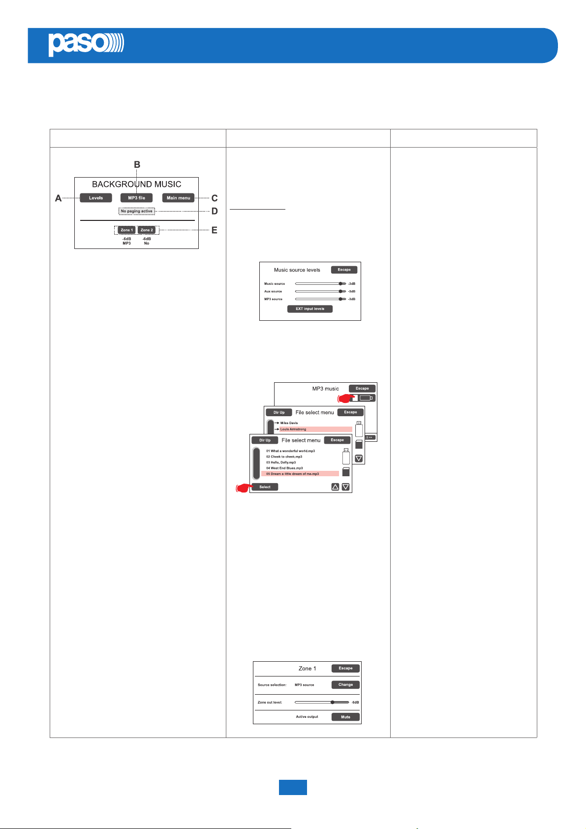
8.2 MUSIC MENU
SETTING THE AUDIO PARAMETERS OF BGM SOURCES
Screen page Description of main panel Description of options
EN
Music source control panel displayed by the
PAW in conditions of normal “Idle” state:
Navigation keys:
Levels (A): Music source levels
Access to the panel for adjusting the input
levels of the available BGM sources.
MP3 fi le (B): MP3 music
Access to the panel for selecting MP3 music
fi les from external media (SD cards or USB
devices).
Thanks to the diff erent panels, the new
PAW5500-VES range systems enable
independent selection of the various
music sources.
By pressing the relevant zone key, one
of the following music sources can be
selected:
- No music
- Music source (MUSIC IN)
- Aux source (AUX IN)
- MP3 source (SD e/o USB)
- EXT1 ÷ EXT6 source (ACPAW-2IN,
ACPAW-6IN).
In each zone panel, slide the cursor
along the bar to adjust the relevant
output volume and to set the required
level of attenuation (from 0 dB to -70 dB/
Off ).
This value will be stored for each BGM
source and shown below the relevant
button.
The output can be activated/muted
using the ‘Mute’ key, without changing
the output level of the zone itself.
Input volume adjustment for all the
sound sources is available on a single
panel (Levels > Music source levels).
Main menu (C)
Access to the main menu screen.
No paging active / Paging active (D)
Indication of the presence of broadcasting
calls.
Zone 1 to 6 (E) > Zone X
Access to the panel for selecting music
sources and adjusting the output level. Press
Change to select the required source and
move the cursor along the ‘Zone out level’ bar
to set the music output volume. Press ‘Mute’
to mute the music without changing its output
level. Press it again to reactivate the music.
System manual PAW5500-VES Compact systems
25
SELECTION OF MP3 FILES
After pressing the ‘MP3 File’ key, select
the device on which to look for the fi les
by clicking on the appropriate icon (SD
or USB stick). Use the ‘Dir Up’ and ‘Dir
Down’ keys to search inside the folders
and the arrows to scroll through the lists
of fi les. After highlighting the required
track, press SELECT: the play panel
with the relevant controls will appear.
ACTIVATION AND DEACTIVATION OF THE
MUSIC FOR EACH OUTPUT ZONE
Music has been activated for a zone
when the relevant key is green. If it is
not activated, the key will be blue.
To change the state of activation, press
the zone key once, then press the
‘Mute’ key.
Page 26
EN
PAW5500-VES
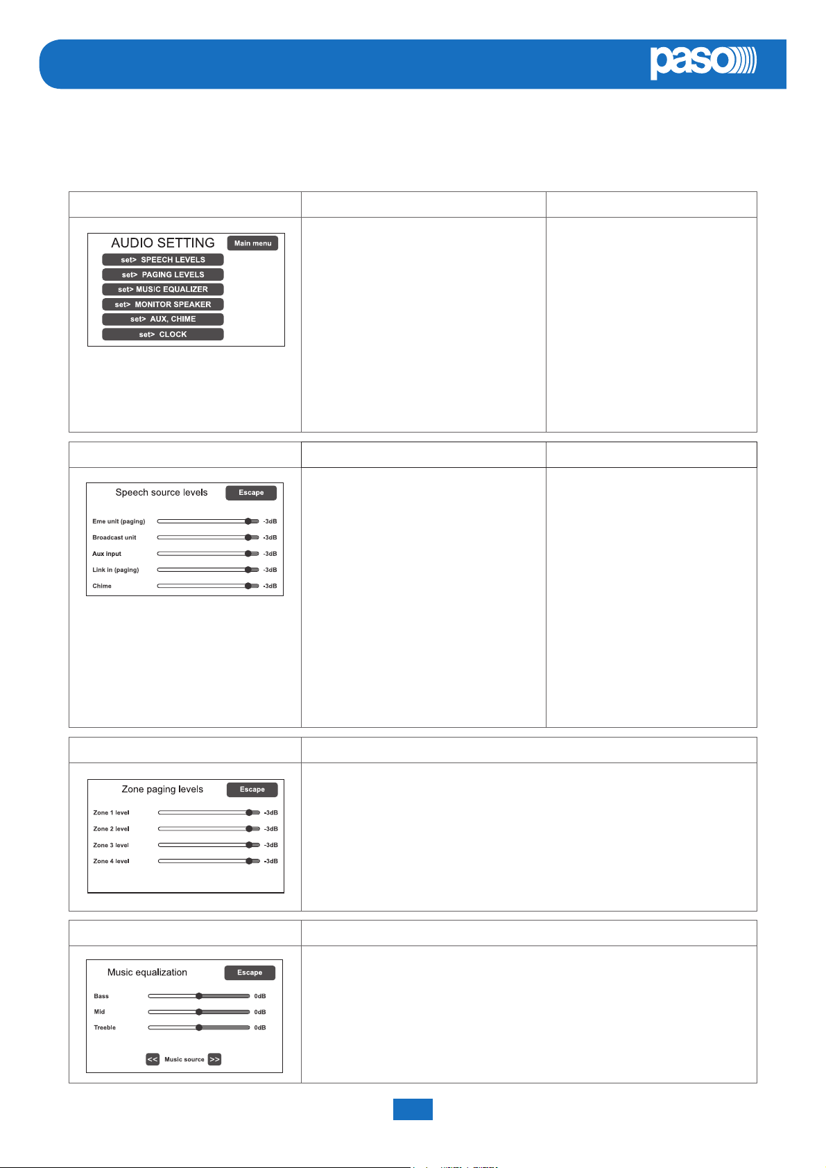
8.3 <AUDIO SETTING> MENU
SETTING THE AUDIO PARAMETERS OF THE PA SOURCES
Screen page Description of the main panel Description of options
Music and broadcast source control panel
displayed by the PAW in conditions
of normal “Idle” state operation.
From this panel it is also possible to set
the timers for programmed playing out of
the broadcast messages.
To select the desired item, press the
relevant key.
To return to the main screen, press ‘Main
Menu’.
set> SPEECH LEVELS Adjustment of the voice sources Relevant items
On this screen page the volume il volume
of the voice sources connected to the
PAW can be adjusted.
The options of the AUDIO SETTING
menu enable access to the
following panels:
set> SPEECH LEVELS
set> PAGING LEVELS
set> MUSIC EQUALIZER
set> MONITOR SPEAKER
set> AUX, CHIME
set> CLOCK
set> TIMERS
Eme unit (paging)
Remote emergency units
on broadcasting calls.
To change the value indicated, move the
cursor along the bar next to each source.
To return to the < AUDIO SETTING >
screen, press ‘Escape’.
set> PAGING LEVELS Adjustment of the output level
On this screen page the output volume during broadcasting calls can be
adjusted zone by zone.
To change the indicated value, move the cursor along the bar next to each
source.
To return to the < AUDIO SETTING > screen, press ‘Escape’.
set> MUSIC EQUALIZER Equalisation of the music source tones
Broadcast unit
Broadcasting stations.
Aux unit
Auxiliary input.
Link in (paging)
Broadcasting calls coming from
other linked PAW’s.
Chime
Warning signal.
On this screen page music quality can be corrected by means of a three-band
equalizer.
To change the indicated value, slide the cursor along the bar next to each band.
To return to the < AUDIO SETTING > screen, press ‘Escape’.
PAW5500-VES Compact systems System manual
26
Page 27
PAW5500-VES
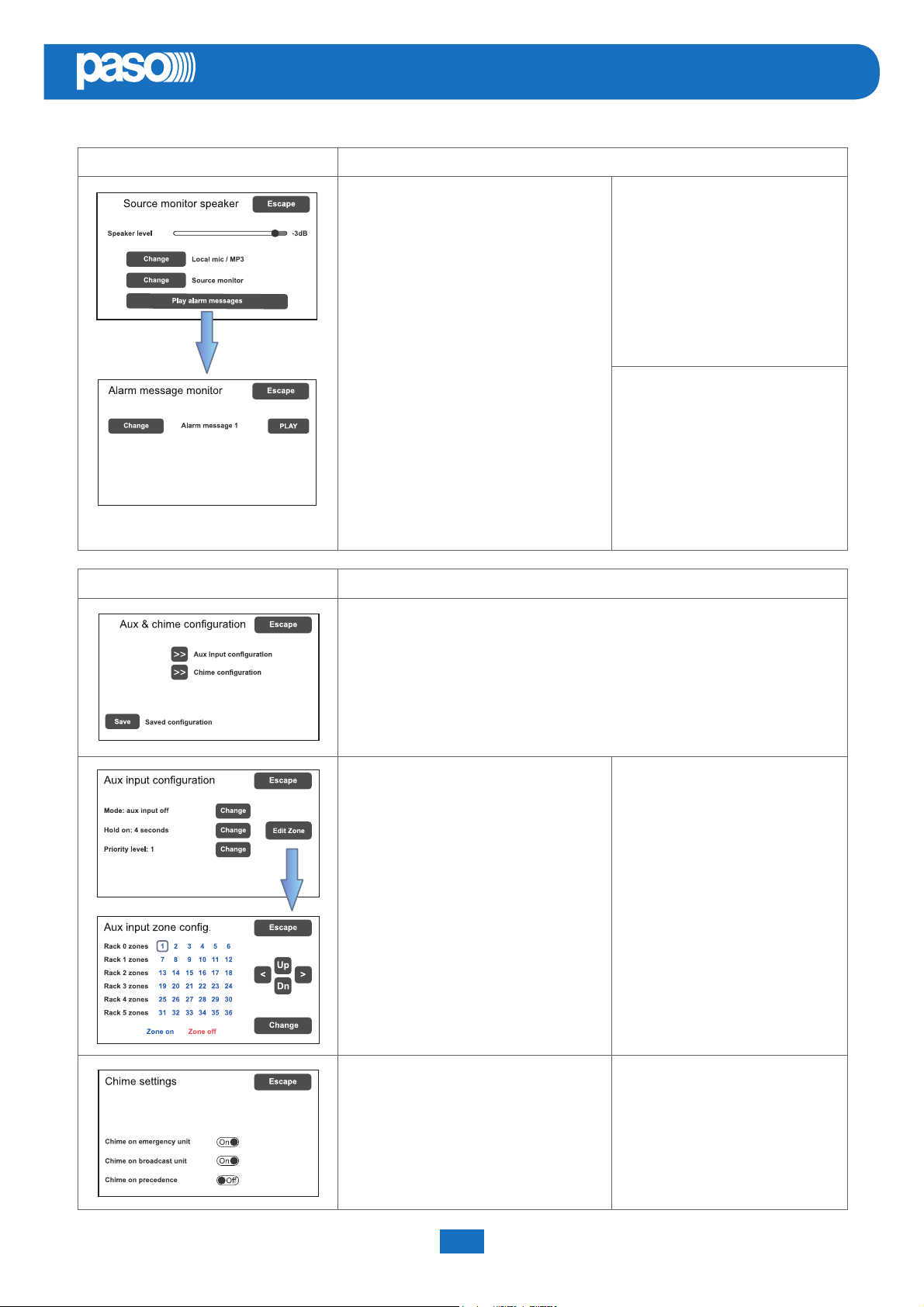
set> MONITOR SPEAKER Management of monitor speaker
On this panel, in addition to adjusting the
volume of the monitor speaker on the
PAW, it is possible to enable sounding
of the input and output signals of the
equipment.
The Source Monitor Speaker screen
enables one of the input sources to be
played back, while the Zone Monitor
Speaker enables one of the output zones
to be played back.
The Play Alarm Messages key enables
access to the screen page where it is
possible to listen via the monitor speaker
to the pre-recorded messages stored
in the PAW’s internal memory. Press
‘Change’ to browse through the various
messages, ‘PLAY’ to start playing and
‘STOP’ to stop it.
EN
Sources available for selection
Local mic / MP3
Emergency units
Link A input
Link B input
Broadcast unit
Music source
Aux source
Ext1 to Ext6 source
Speaker monitor off
Selectable zones
Output on zone X
Speaker monitor oFF
set> AUX, CHIME Management of AUX and CHIME inputs
Confi guration of the auxiliary input and of the chime is accessed from this panel.
Aux input confi guration
On this screen the confi guration of the
auxiliary input can be set, selecting the
Mode, the hold-on time for VOX at the end
of a call and the Priority Level of a call.
Using the Edit zone button, another
screen page is accessed where the call
zones can be selected upon activation
of the AUX input, using the arrow and
Up/Dn keys.
Mode
Aux input off
Input VOX level 1÷7
Aux input on
Aux with prec.
Aux with prec.
Precedence modes also require
appropriate setting of the P+/P- jumper
on the CPU board.
Hold on
0 / 1 / 2 / 4 / 8 / 16 sec.
Priority level
1÷7
+
–
Chime confi guration
On this screen, chimes for calls
coming from emergency stations,
from broadcasting stations or from the
precedence contact can be enabled or
disabled independently.
System manual PAW5500-VES Compact systems
27
Chime on emergency unit (on/off )
Chime on broadcast unit (on/off )
Chime on precedence (on/off )
Page 28
EN
PAW5500-VES
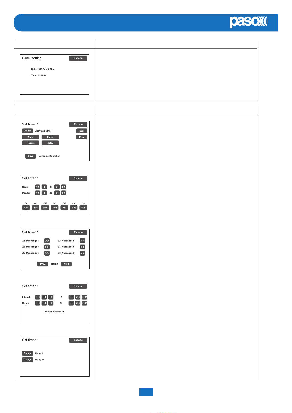
set> CLOCK Displaying current date and time
On this screen page the system time can be displayed (it is not possible to make
any changes, which are permitted at the higher access levels).
Press ‘Escape’ to return to the < AUDIO SETTING > screen.
set> TIMERS Setting the timers
On this screen it is possible to set up to 16 timers that enable timed events
(such as sending of broadcast messages) to be activated and/or the activation
of relays.
Press ‘Next’ and ‘Prev.’ Keys to select the required timer (from 1 to 16).
Pressing the ‘Change’ key, to set the timer state:
- Activated timer (timer activated)
- Not activated timer (timer not activated)*
*The second option enables temporary de-activation of a timer that has been set.
Press ‘Timer’ to set the timer on a weekly basis.
Use the << / < and > / >> keys to set the time and to select the days on which
the event should be called up.
Press ‘Zones’ to select the message and the zone in which it is to be played out.
If there are more than one PAWs in the system, the zones controlled by these
card-cages can also be selected.
Press ‘Repeat’ to set the timer repetitions, expressed in minutes:
- Interval (interval between repetitions)
- Range (total duration of the repetition)
Press ‘Relay’ to activate one of the relays*.
*If available, that is to say not already programmed during confi guration for other
events.
To return to the < AUDIO SETTING > menu press Escape.
PAW5500-VES Compact systems System manual
28
Page 29
PAW5500-VES
8.4 <INSPECTION> MENU
SYSTEM STATUS INSPECTION
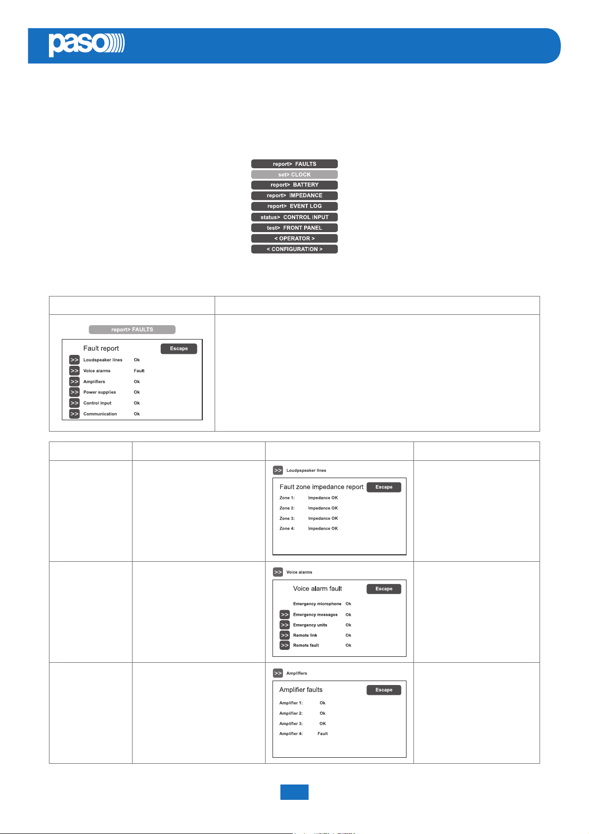
This menu is intended for selecting options for system status inspection.
It is for use by the personnel in charge of initial checking of the causes leading to a fault or to an emergency state.
In this menu it is possible to select:
To return to the main screen press Main menu.
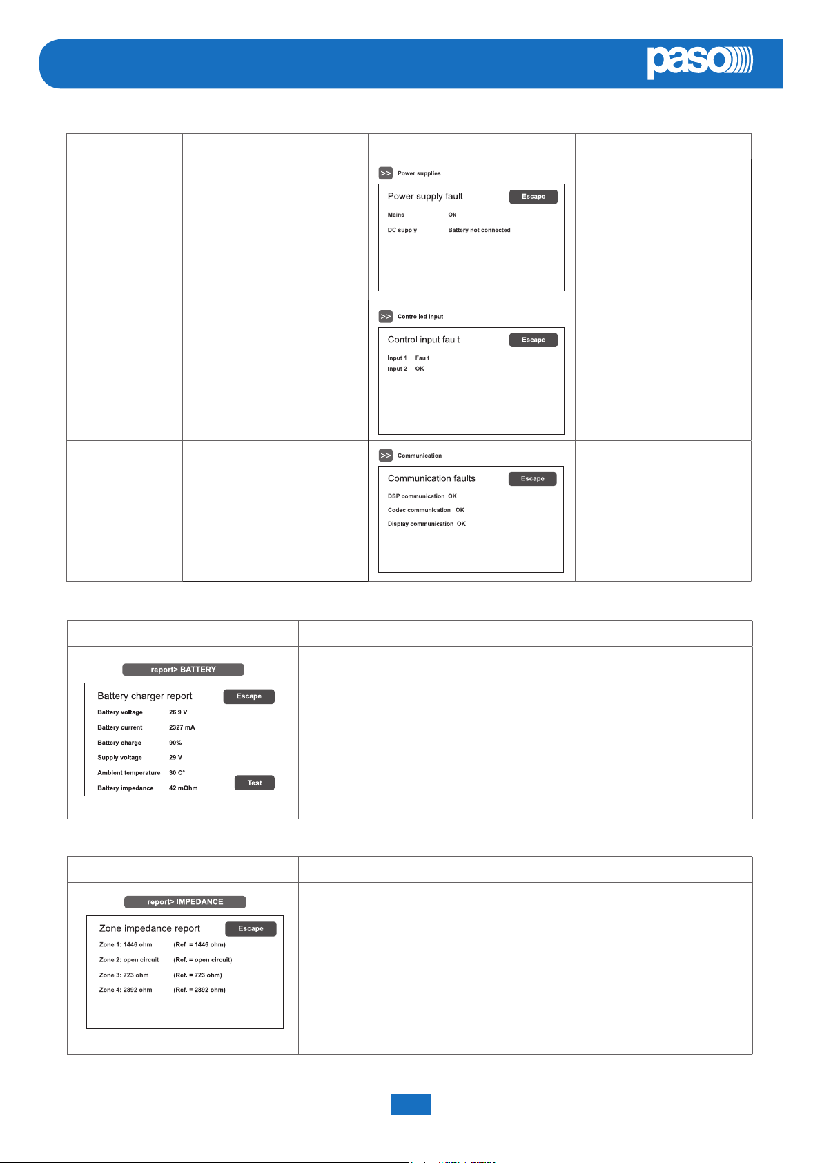
report> FAULTS Investigation on faulty conditions
EN
Six items are listed with a general indication of the fault status.
The categories of the faulty parts and the status general reporting are shown in
the following table.
Press the required item to access the chosen sub-panel and view the details of
the fault as illustrated on the following screens.
To return to the INSPECTION menu press Escape.
Label
Loudspeaker lines Loudspeaker lines
Voice alarms Voice emergency sources
Category subject to diagnosis
See panel Notes
The diagnosis status is
reported for each output line.
For each monitored element,
additional sub-panels can
be accessed, where the
diagnosis status is reported.
The diagnosis status is
Amplifi ers Amplifi ers
System manual PAW5500-VES Compact systems
29
reported for each monitored
element.
Page 30
EN
PAW5500-VES
Label
Power supplies
Control input Local input contacts
Communication Internal communication of PAW
Category subject to diagnosis
Primary and secondary power
supplies
See panel Notes
The diagnosis status is
reported for each monitored
element.
The diagnosis status is
reported for each monitored
element.
The diagnosis status is
reported for each monitored
element.
report> BATTERY Status of batteries
This panel displays all the data relating to the internal batteries of the PAW.
The equipment carries out testing of the batteries automatically approximately
once an hour. It is in any case possible to start an immediate test manually
by pressing the ‘Test’ key. If the batteries have not been fi tted, the only values
detected will be the power supply voltage and the temperature.
To return to the INSPECTION menu, press Escape.
report> IMPEDANCE Impedance of the lines
Panel for checking the impedance values measured in real time compared with
the value stored during the start-up (see page 36).
If the tolerance is exceeded, the fault will be reported in the relevant menu
together with a too high, too low or short-circuit impedance value.
To return to the INSPECTION menu, press Escape.
PAW5500-VES Compact systems System manual
30
Page 31
PAW5500-VES
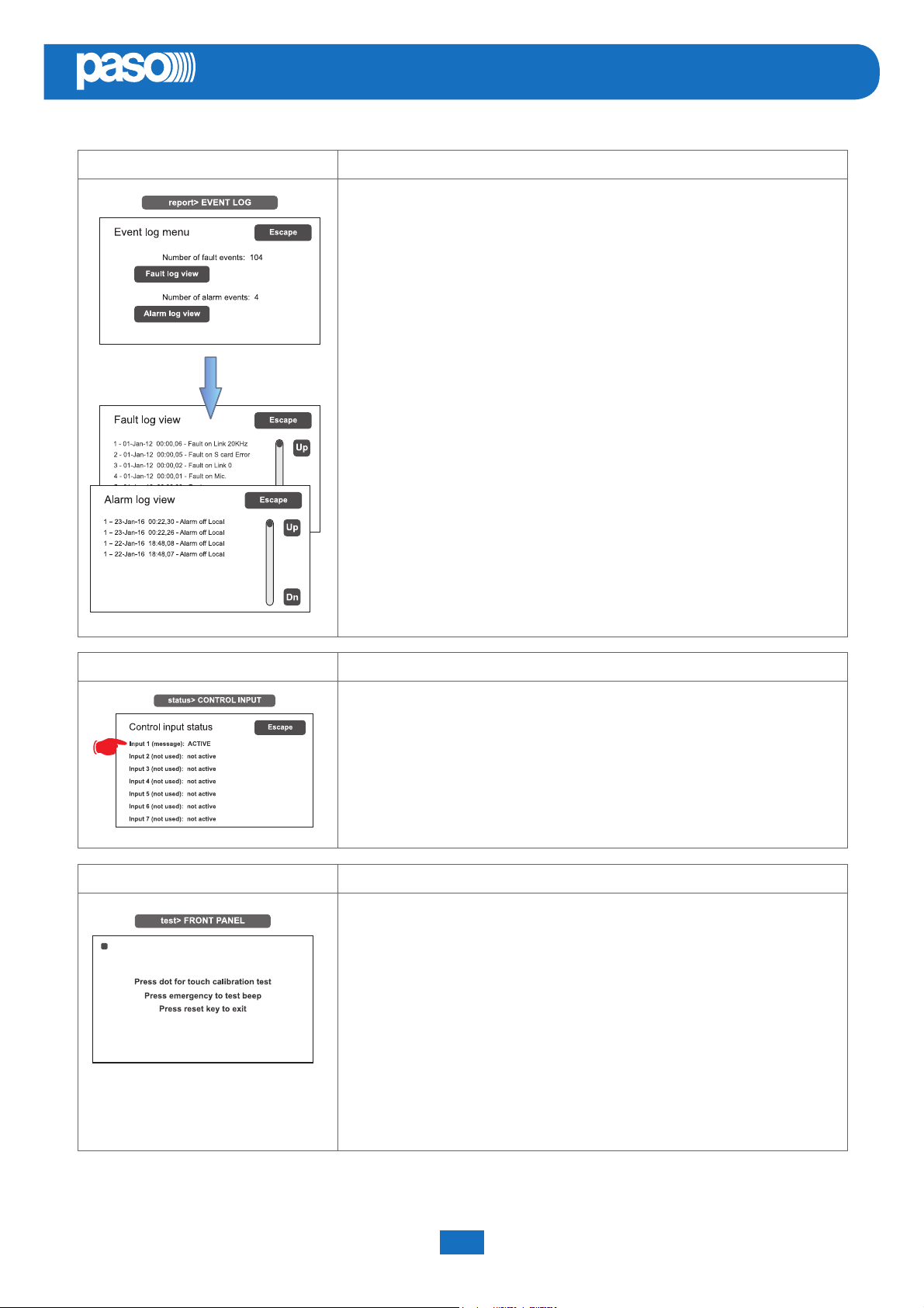
report> EVENT LOG Event log
This panel displays a report showing the total number of faults and alarms
recorded during system operation.
Press Fault log view for a detailed view of the faults.
Press Alarm log view for a detailed view of the alarms.
To return to the INSPECTION menu, press Escape.
EN
status> CONTROL INPUT Status of the local input contacts
This panel shows a list of the controlled inputs, their types (message, reset, not
used) and their statuses (input active/not active).
In the event of activation of one of these inputs, the system will enter an “Alarm
status”, light up the ALARM LED and show automatically the panel indicating
which PAW zones are aff ected by the emergency (see under Activation of an
automatic emergency, page 46).
To return to the INSPECTION menu, press Escape.
test> FRONT PANEL Check of operation of the visual and acoustic signalling devices
Panel for checking operation of the monitor speaker, of the display, of the touch
screen and of the signalling LED for the emergency operations.
With the exception of the yellow SYS LED, which remains OFF, all the other
LEDs and the emergency button will be in the fl ashing mode. The screen
background colour changes in sequence so as to check correct functioning of all
the pixels.
Press the small black square that appears on the display to check proper
calibration of the touch screen.
Press the EMERGENCY button to test correct sounding of the “beep” by the
monitor speaker as well as button effi ciency.
To return to the INSPECTION menu, press RESET.
The < OPERATOR> and <CONFIGURATION> keys can be used to go on to the subsequent menus.
System manual PAW5500-VES Compact systems
31
Page 32
EN
PAW5500-VES
8.5 <OPERATOR> MENU
MANAGEMENT OF EMERGENCY, FAULTY AND DISABLED CONDITIONS
Menu from which to select options, to be used only by the personnel in charge of managing the system in the event of an emergency
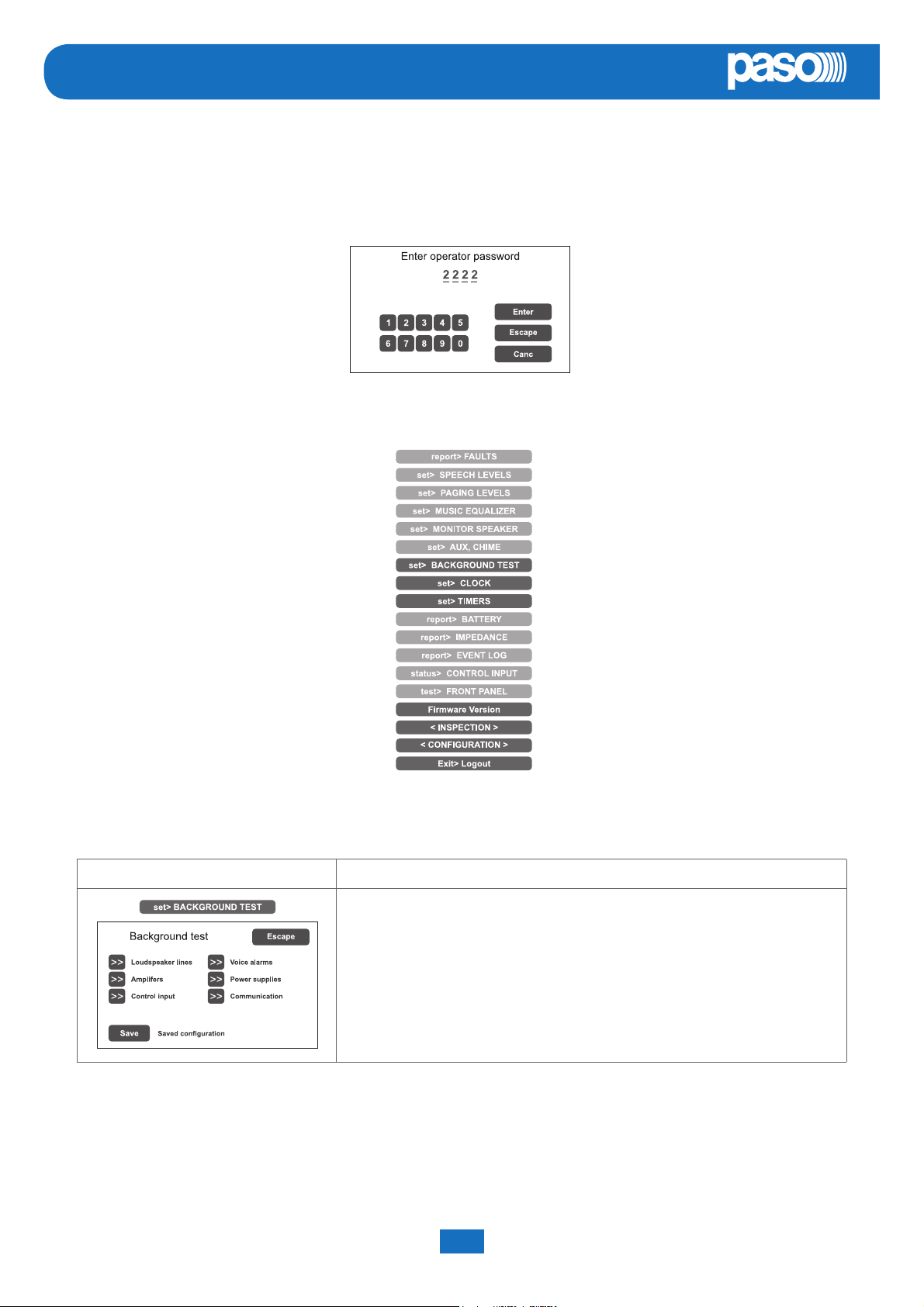
and/or a fault. If a login password was enabled at the time of confi guration, the following panel will appear:
Enter the 4-digit numerical password (it is 2222 by default) and press Enter.
Once the OPERATOR menu is accessed, new items in addition to those already seen will be found.
> Further functions
To return to the main screen page press Main Menu.
set> BACKGROUND TEST Enabling and disabling of the monitoring tests
Panel for enabling and disabling the monitoring tests applied to those items
aff ecting the system functioning in emergency conditions.
Select the required item(s) in order to access the relevant sub-panels *.
If the parameters of one or more items are changed, press Save to save the
new confi guration.
To return to the OPERATOR menu press Escape.
*
For details see the table on page 33.
Note:
Upon access to the various panels shown below, the touch screen shows the programming status as currently set.
To change this status move the cursors to the desired positions – as indicated in the table - and then press ‘Save’ on the
set> BACKGROUND TEST panel.
PAW5500-VES Compact systems System manual
32
Page 33
PAW5500-VES
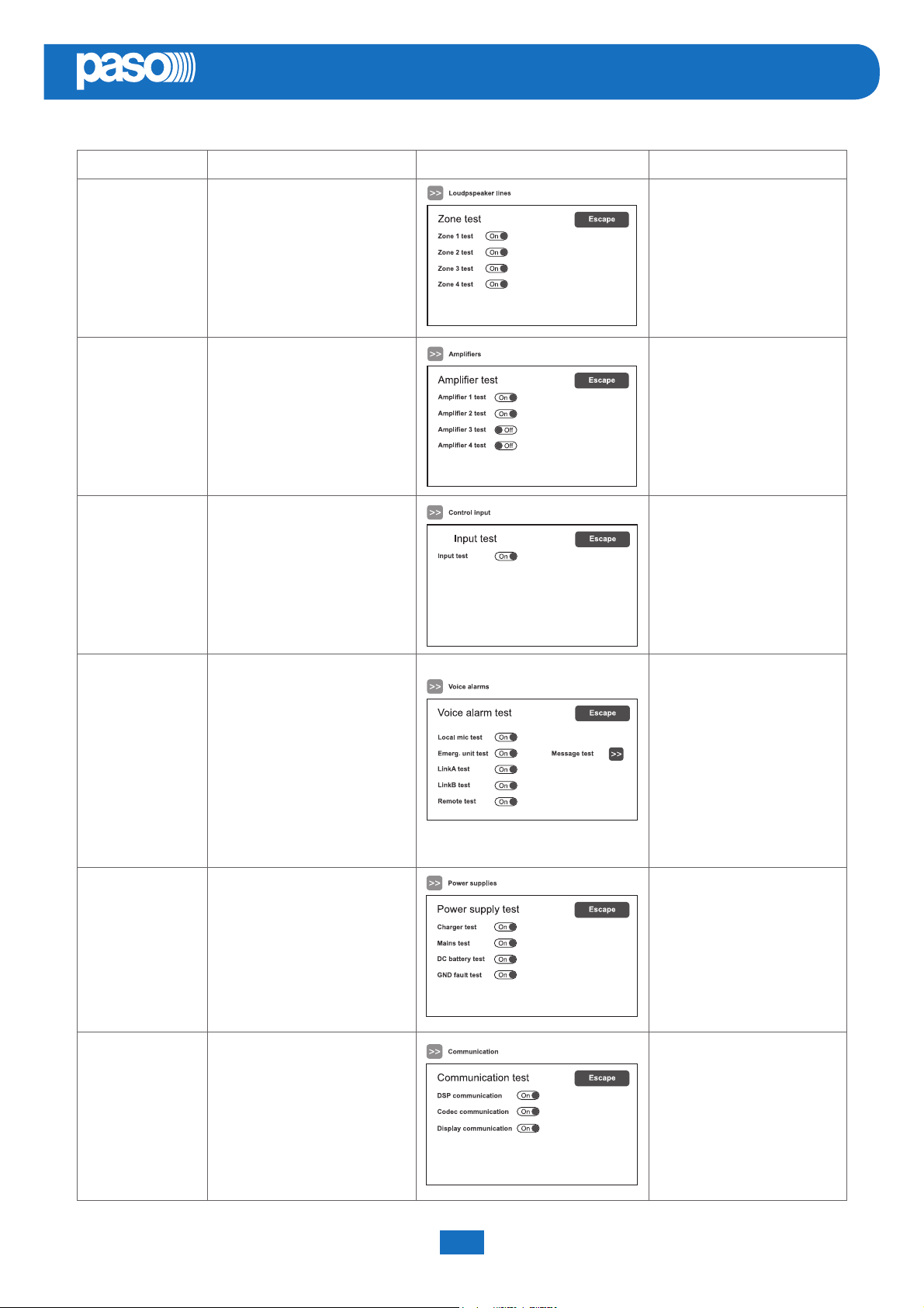
Label Application See panel Notes
Panel for testing the
loudspeaker lines.
Loudspeaker lines Loudspeaker lines
Amplifi ers Amplifi ers
On = test enabled
Off = test disabled
Panel for testing the local
amplifi ers.
On = test enabled
Off = test disabled
EN
Control input Controlled inputs
Voice alarms Voice emergency sources
Power supplies Power supplies
Panel for testing the input
contacts.
On = test enabled
Off = test disabled
Panel for testing the incoming
emergency sources:
- Testing of handheld micro
- Testing of emergency units
- Tetsing messages
- Testing Link A
- Testing Link B
- Testing of remote PAWs
On = test enabled
Off = test disabled
Panel for testing of power
supplies:
- Testing of battery charger
- Testing of mains supply
- Testing of 24 VDC batteries
- Testing of GND fault
On = test enabled
Off = test disabled
Panel for testing of internal
data communication of PAW:
- Testing of DSP comm.
Communication
System manual PAW5500-VES Compact systems
Internal communication
of PAW
33
- Testing of codec comm.
- Testing of display comm.
On = test enabled
Off = test disabled
Page 34
EN
PAW5500-VES
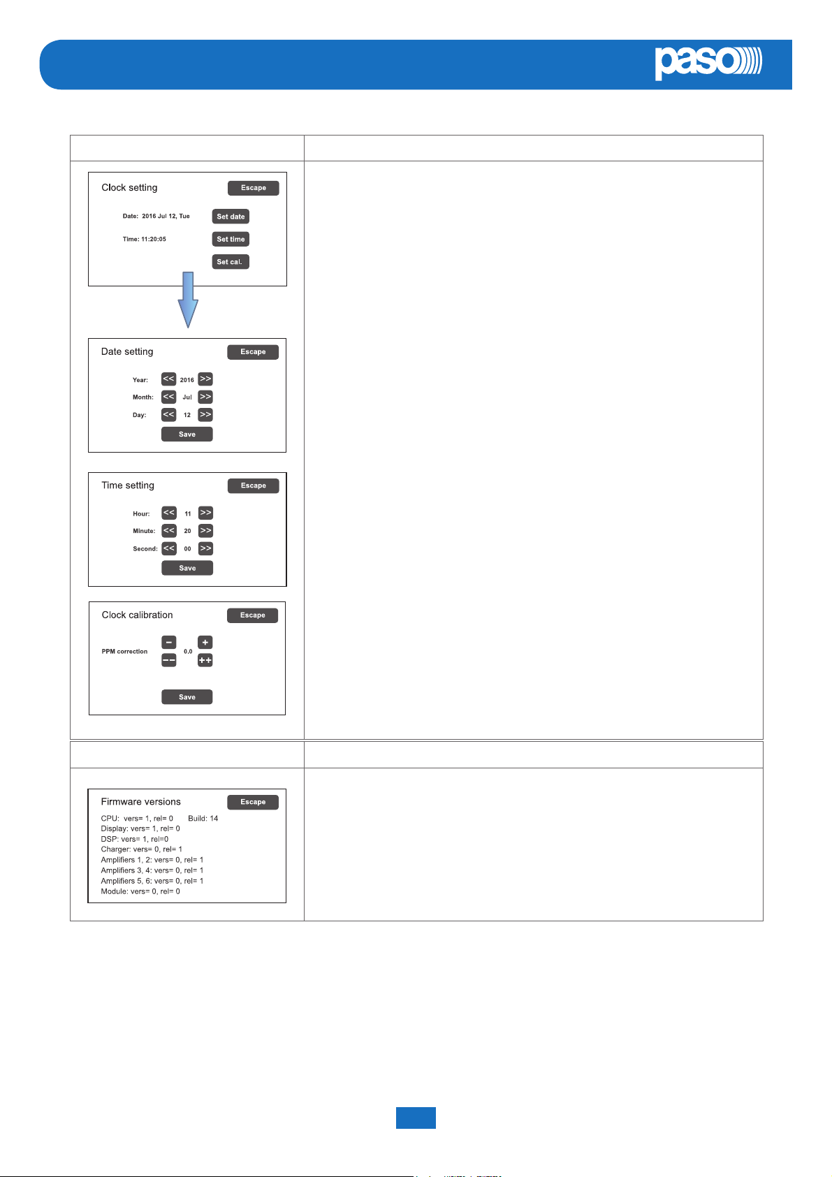
set> CLOCK Setting of system date and time
Panel for setting the system date and time.
Press the following buttons:
- Set date (date)
- Set time (hour) and
- Set cal. (calibration)
to set these parameters.
To return to the OPERATOR menu press ‘Escape’.
After setting the desired date, press ‘Save date’ before pressing ‘Escape’ to exit.
After setting the desired time, press ‘Save time’ before pressing ‘Escape’ to exit.
The Clock Calibration window enables fi ne setting of the clock.
It is advisable to check the diff erence in seconds compared with a high-precision
clock after a couple of days. Calculate the diff erence in parts per million (over or
under) and enter the result by means of the ‘PPM correction’ keys.
Then press ‘Save’ to save the setting.
Press ‘Escape’ to exit.
set> Firmware Version Viewing the fi rmware version
Panel for viewing the version of the fi rmware installed in the PAW system.
To return to the OPERATOR menu press ‘Escape’.
Use the < INSPECTION > and <CONFIGURATION> key to access the relevant menus.
! N.B.:
Upon completion of the operations carried out, before returning to the basic level, that is to say to the MUSIC MENU,
it is advisable to log out of the system level corresponding to the current menu, so as to reset the required password
for future accesses and to prevent unauthorised personnel from accessing the advanced functions of the system
To do this, select Exit> Logout from the list in the OPERATOR menu: the system returns to its basic level and shows the
MUSIC MENU panel. The request for the login password will be reset also for any other levels visited. Otherwise, after 5
minutes without any keys being pressed, the system will automatically reset the password.
PAW5500-VES Compact systems System manual
34
Page 35
PAW5500-VES
EN
8.6 <CONFIGURATION> MENU
MANAGEMENT OF ADVANCED SYSTEM FUNCTIONS AND CONFIGURATION CHANGES
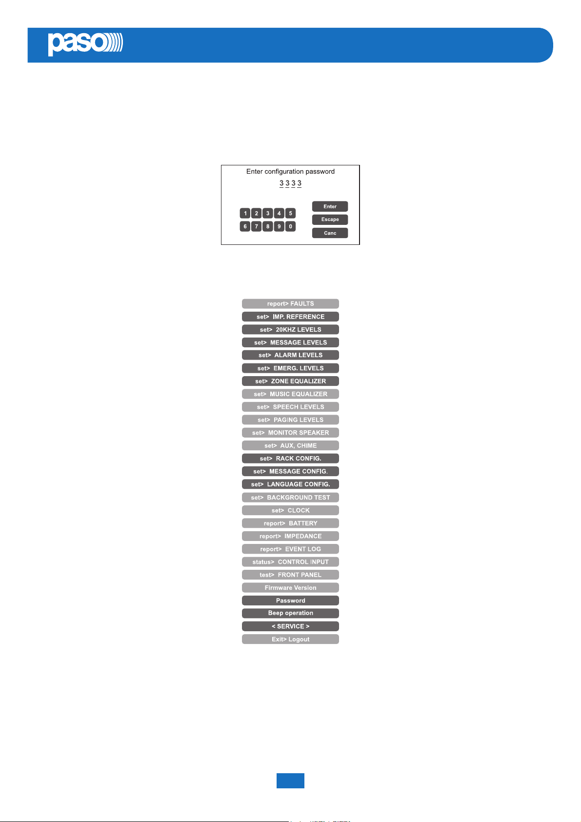
This option selection menu is for use only by specifi cally trained personnel authorised to work on advanced system
functions and to modify the confi guration parameters, for system start-up and maintenance purposes. If a login
password was enabled at the time of confi guration, the following panel will appear:
Enter the 4-digit numerical password (it is 3333 by default) and press Enter.
Once the CONFIGURATION menu is accessed, additional new items will be seen.
To return to the main screen, press Main Menu.
System manual PAW5500-VES Compact systems
35
Page 36
EN
PAW5500-VES
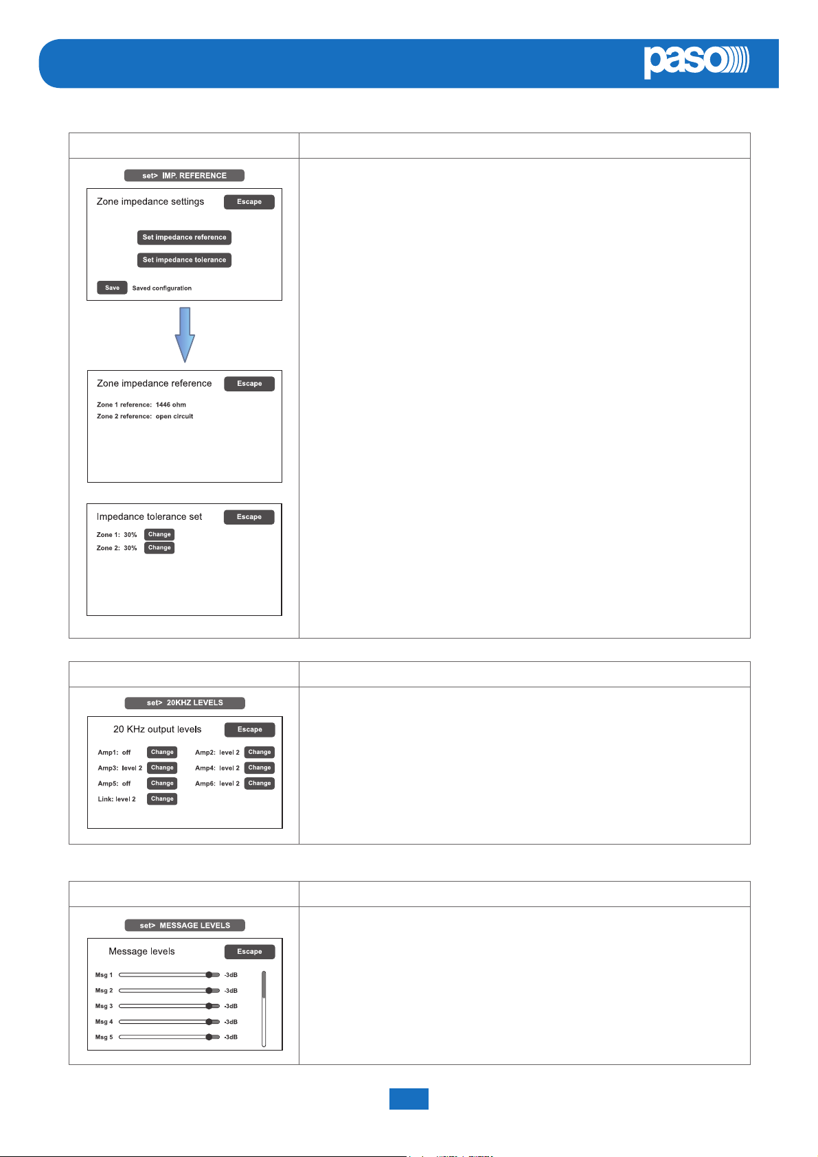
set> IMP. REFERENCE Impedance acquisition and tolerance setting
Panel for acquiring line impedance values and setting the tolerance threshold for
the diagnostic tests.
Press the appropriate buttons to access the sub-panels.
Please note that if the new impedance and tolerance values are accepted, they
will have to be saved by pressing the ‘Save’ key.
The Zone impedance reference panel shows the impedance values measured
on the output zones, which will constitute the reference values.
Use the Set impedance tolerance panel to defi ne the tolerance, choosing one
of the suggested values (press the Change key associated with the desired
zone and set one of the following values: 10%, 20%, 30%, 40% or 50%).
When the diagnostic system detects a value beyond the tolerance chosen for
the reference value, a ‘Fault’ is activated.
To return to the CONFIGURATION menu, press Escape.
set> 20KHZ LEVELS Setting the test signal level
Panel for setting the test signal levels to 20 kHz in the various audio channels.
Press the Change keys associated with the level to be adjusted and select one
of the following options: level 1, level 2, level 3 or Off .
The recommended value for the amplifi ers is 2, while for a link it should be
chosen on the basis of the distance between the racks.
To return to the CONFIGURATION menu, press Escape.
set> MESSAGE LEVELS Setting message levels
Panel for setting the levels for the messages stored in the card-cage memory.
Move the cursors along the bars to adjust each level.
To return to the CONFIGURATION menu, press Escape.
PAW5500-VES Compact systems System manual
36
Page 37
PAW5500-VES
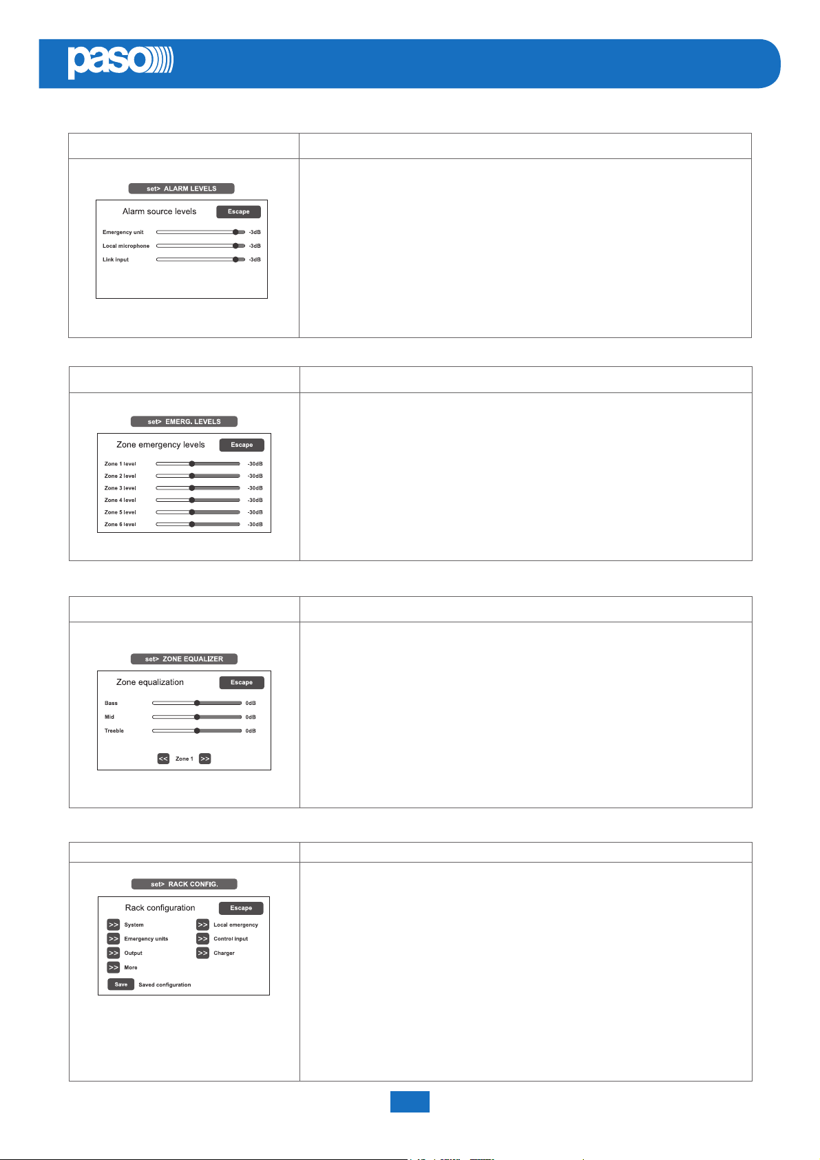
set> ALARM LEVELS Setting the alarm source level
Panel for setting the output volume of the alarm sources connected to the
PAW5500-VES.
- Emergency units.
- Hand-held paging local microphone.
- LINK input (connection with other PAWs).
To return to the CONFIGURATION menu, press Escape.
set> EMERG. LEVELS Setting the zone volume level during emergencies
Panel for adjusting the zone volume during emergencies.
EN
To return to the CONFIGURATION menu, press Escape.
set> ZONE EQUALIZER Equalisation of the zone tones
Panel for equalising the bass, mid-range and treble tones in each output zone.
To return to the CONFIGURATION menu, press Escape.
set> RACK CONFIG. Rack confi guration
This panel contains all the parameters needed for confi guring the rack:
- System.
- Emergency messages to broadcasting zones.
- Emergency unit.
- Controlled inputs.
- Outputs.
- Battery charger.
- Selection of optional cards / Local broadcasting unit.
Note that any changes whatsoever to any of the sub-panels illustrated on the
following page must be saved by pressing the Save button.
To return to the CONFIGURATION menu, press Escape.
System manual PAW5500-VES Compact systems
37
Page 38
EN
PAW5500-VES
Label Application See panel Notes
System
System confi guration
Standby amplifi er
Local emergency Local emergency
In this panel the following are set:
- PAW ID address (0 to 5).
- Number of PAWs in the system.
- Attribution of standby amplifi er.
The total number of amplifi ers
present in the system is also
shown automatically.
Panel for setting the default
broadcasting zones for emergency
messages. The situations of all
the PAWs present in the system
is shown. Use the Up and Dn and
arrow keys to move through the
table. For the remote racks, the
values selected refer to all the
zones.
Press ‘Change’ to change the
zone status, choosing between:
blue = active zone and
red = inactive zone
Emergency units Emergency units
To leave this screen, press
‘Escape’.
From this panel it is possible to
use the sub-menus to set the
confi gurations of the emergency
units connected to the PAW.
To confi gure the PMB132 range
emergency units, press ‘Set
unit with keys’, then press the
‘Change’ key to select the model.
Then press ‘Edit key’ for
confi guring the keys.
Use the ‘<<’ and ‘>>’ keys to pass
from one key to another of the
unit. Move over the table using the
< and > keys and the Up/Dn keys.
Press ‘Change’ to change the
association of the zone with the
key, choosing between:
Blue = Zone associated
Red = Zone not associated
To leave the screen, press
‘Escape’.
The item ‘Set unit with touch
screen’ refers to the presence of
the TSB8500-V touch screen unit.
PAW5500-VES Compact systems System manual
38
Page 39
PAW5500-VES
Label Application See panel Notes
Panel for confi guring the controlled
inputs. To go from one input to
another (from 1 to 7), press Next
or Prev.
Press Mode to select one of the
following modes:
- Message input > Edit zone
- Broadcast > Edit zone
Press ‘Edit zone’ to associate a
message with each zone
- Not active input
- Reset input
Press Control to enable or disable
control over the concerned input.
Press Logic to set the logic
typology attributed to the
Control input Controlled input contacts
concerned input, choosing
between:
- Positive (active high)
- Negative (active low)
EN
Output Relay outputs
Press Trans to choose the
operating mode:
- Level: the messages are
activated only for as long as the
input is activated.
- Transition: activation of the
messages starts with activation of
the input, but can be stopped only
by means of manual resetting or a
reset input.
Press Priority to select the level
of priority of transmission from the
broadcast messenger
Press ‘Escape’ to exit the screen
page.
Panel for confi guring the outputs.
To go from one output to another
(from 1 to 3), press Next or Prev.
Activate or de-activate (On/Off ) the
type of event to be associated with
the output in question by pressing
the appropriate buttons.
To leave the screen, press
‘Escape’.
System manual PAW5500-VES Compact systems
39
Page 40
EN
PAW5500-VES
Label Application See panel Notes
Panel enabling two selections to
be made:
- Optional cards
- Local unit confi g.
On the ‘Optional cards’ screen,
press the >> key to select and
enable the optional card, if any,
present in the system (ACPAW-
2IN or ACPAW-6IN).
More
Selection of optional cards
Local broadcasting unit
On the ‘Local unit confi g.’
screen, slide the cursors to
select up to 4 broadcast stations
to be used in the local mode
(included among the 16 that
are permitted). On activating
this function, keys 1 to 6 of the
station will correspond, in the
same order, to the zones of the
card-cage to which the station
itself is connected (e.g. if the
local base is connected to cardcage 2, key 1 will correspond to
zone 13, key 2 to zone 14 and
so on). It is advisable to use
Paso PMB106-G units as local
stations.
Battery confi guration panel.
By pressing ‘Change’ it is possible
to set:
- The capacity of the battery
(choose 18, 26, 33 or 40 Ah).
Charger Battery charger
PAW5500-VES Compact systems System manual
2 AMP (Pmax = 250W)
Capacity Duration without mains supply
18 Ah 24 h + 30 min*
26 Ah 35 h + 30 min
33 Ah 44 h + 30 min
40 Ah 72 h + 30 min
4/6 AMP (Pmax = 500W)
Capacity Duration without mains supply
26 Ah 24 h + 30 min*
33 Ah 30 h + 30 min
40 Ah 36 h + 30 min
40
- ‘Energy save’ mode enabled
disabled. This enables the
batteries to remain in the
energy saving mode when
there is no mains power.
*According to UNI ISO 7240-19
point 5.15.3 requirements:
24 h standby plus 30 minutes in vocal
alarm condition.
Page 41
PAW5500-VES
set> MESSAGE CONFIG. Setting of emergency messages
The default messages (Alert, Evacuation and warning signal/chime) are stored
in the PAW5500-VES internal fl ash memory. To further customise the system, it
is also possible to load customised WAV fi les from external devices (an SD card
or USB memory stick). To do this, it is necessary to:
- Use the << and >> keys to select the message to be loaded.
- Press ‘Load new fi le’ to go and select the fi le in the SD card or on the USB
stick in the specifi c search window.
- Select the fi le by pressing ‘Select’ and then confi rming with ‘OK’.
The display will show the stages of cancellation of the old contents followed
by recording of the new message, played out at the same time via the
monitor loudspeaker. Upon completion the ‘Message confi guration’ screen
will reappear.
Message attributes:
Evac: the message is considered an evacuation message and therefore has a
higher priority than an alert.
Alert: the message is considered an alert and therefore has a lower priority than
an evacuation message.
Broadcast: this is a general announcement, suppressed in emergency
conditions. It is used associated with a broadcast input with the related priority.
None: The message is not used.
EN
To change the attribute of a message, use the ‘Change’ key.
N.B.: Messages 1 and 2 have fi xed attributes, that is to say EVAC and ALERT
respectively. It is compulsory for the system to have at least these two messages,
which can be called up from local and remote stations. All the messages with the
attributes EVAC or ALERT are subjected to checksum tests and in the event of an
error their failure is signalled.
To return to the CONFIGURATION menu, press Escape.
set> LANGUAGE CONFIG. Selecting the language
The factory-set default language is English. The new PAW5500-VES range
enables other languages, pre-installed and stored in the internal fl ash memory,
to be chosen.
Use the << and >> keys to browse through the available languages. When
the required language is shown, press Save. The new menus will be loaded
immediately and the MUSIC screen page will reappear on the display.
To return to the CONFIGURATION menu, press Escape.
System manual PAW5500-VES Compact systems
41
Page 42
EN
PAW5500-VES
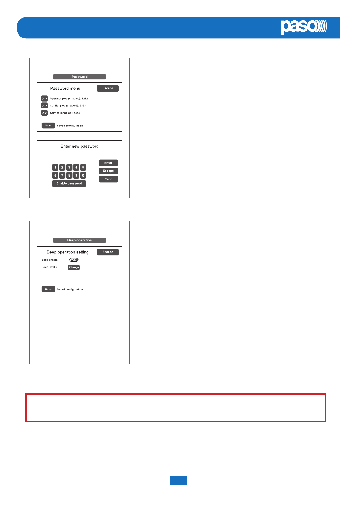
Password Setting a password
Panel for enabling, disabling and customising the password for logging into the
system service levels. The default passwords set are those shown here on the
left. To change these settings and enter a new code, press the key associated
with the menu in which the change is to be made and, on the next sub-panel,
enter the new password.
To correct a typing error, use the Canc key.
To enable / disable a password, use the Enable password or Disable
password keys (as the case may be).
Press Enter to confi rm and return to the Password menu panel.
Press Save to save the change made.
To return to the CONFIGURATION menu press Escape.
Beep operation Set the control ‘beep’
IMPORTANT NOTE!
From this screen, the acoustic fault (conventionally known as a ‘beep’) can be
set.
- Beep enable / disable:
Move the cursor to the ‘On’ position (beep enabled) or to the ‘Off ’ position
(beep not enabled), as needed (see the “N.B” note below).
- Beep level:
Adjustment of the beep volume, which can be set at one of three diff erent
levels (1 / 2 / 3 / Off ). Press the Change key until the desired volume is
reached.
To return to the CONFIGURATION menu, press Escape.
! N.B.
In order to comply with the regulations, before using the equipment for
normal operation it is necessary to enable the acoustic signalling by setting
‘Beep enable’ to the ‘On’ position.
<SERVICE> MENU FOR TECHNICAL ASSISTANCE OPERATORS ONLY
Fourth access level, included in the CONFIGURATION menu options. Its use is permitted only to those members of
the technical service personnel who have appropriate login passwords.
PAW5500-VES Compact systems System manual
42
Page 43

PAW5500-VES
EN
8.7 CRITERIA FOR MANAGING PRIORITIES IN EMERGENCY CONDITIONS
THE SYSTEM MANAGES EMERGENCY CONDITIONS ON THE BASIS OF TWO CRITERIA:
8.7.1 MANAGEMENT OF PRIORITIES ON THE BASIS OF HOW EMERGENCIES ARE ACTIVATED
There are two possible types of activation:
MANUAL EMERGENCY: emergency state activated by the operator by means of the LED pushbutton on the card-cage
local controls or on the emergency microphone stations.
AUTOMATIC EMERGENCY: emergency state activated from control inputs.
Depending on the management system, it is possible that only one operator can activate a MANUAL EMERGENCY; in this
case, the local controls of the card-cages have maximum priority.
In a system with more than one card-cage, the fi rst card-cage to activate the emergency has priority.
The emergency stations follow in the order of priorities, on the basis of the level set on the base itself.
The AUTOMATIC EMERGENCY condition, on the other hand, is always in addition to the MANUAL EMERGENCY, if any,
and, if necessary, it can be excluded by the latter.
8.7.2 MANAGEMENT OF PRIORITIES OF ALARM MESSAGES
When diff erent alarm messages are called up on a given zone from diff erent sources (local controls, remote microphone
stations, control inputs and remote card-cages), the system will choose the message to be sent out depending on how the
priorities are managed. The order of priority is indicated below, starting from the highest priority down to the lowest:
1. Handsfree messages from a local unit/ remote station / remote control unit (in this case all pre-recorded messages will be
muted).
2. EVACUATION message (message 1) activated by a MANUAL EMERGENCY.
3. ALERT message (message 2) activated by a MANUAL EMERGENCY.
4. Message 1 activated by an AUTOMATIC EMERGENCY.
5. Mess
6. Message 2 activated by an AUTOMATIC EMERGENCY.
7. Messages numbered from 3 to 8 in this order, with the ALERT attribute activated by an AUTOMATIC EMERGENCY.
ages numbered from 3 to 8 in this order, with the EVAC attribute activated by an AUTOMATIC EMERGENCY.
System manual PAW5500-VES Compact systems
43
Page 44
EN
PAW5500-VES
8.8 MANUAL EMERGENCY
THE PROCEDURE FOR MANAGING EMERGENCIES IN THE MANUAL MODE (TO BE CARRIED OUT BY AN AUTHORISED OPERATOR) IS DESCRIBED BELOW.
8.8.1 GENERAL INFORMATION
The manual emergency mode can be accessed at any time and has priority both over any pre-recorded messages under
way - that may have been activated by an external peripheral unit connected to the controlled inputs (9) – and over any
emergency units able to function on the output lines from the PAW being used.
8.8.2 MANUAL MANAGEMENT OF AN EMERGENCY
The PAW enables structured management of alarm messages, of their muting and of the selection of zones, as described in
greater detail below. Following is a list of operations for a fast approach to manual emergencies.
8.8.3 SENDING OUT OF A LIVE EMERGENCY NOTICE
FROM THE PAW
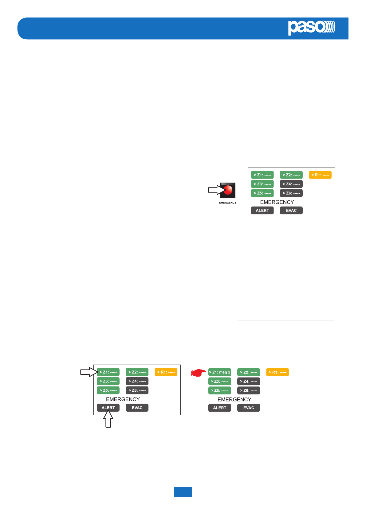
1) Lift the safety lid and press the EMERGENCY key (5) once.
It lights up steadily.
The display shows the PAW output zones. The fact that the
system has been placed in a state of emergency is shown
simultaneously on any stations and PAW s present in the
system.
2) To send:
A voice message > Select the desired zones and racks, then use the hand-held microphone (3) to speak, keeping the
button on its side pressed.
A pre-recorded ALERT message > Select the desired zones and racks and press ALERT.
A pre-recorded EVACUATION message > Select the desired zones and racks and press EVAC.
In both cases, the keys on the display will show the type of message being broadcast in each zone.
Note:
If the PTT key of the hand-held microphone or the ALERT or EVAC keys are pressed without selecting any zones beforehand,
the message will be sent out as set at the time of system confi guration (see set> RACK CONFIG. > Local emergency on
page 38). The zones selected at the confi guration stage are highlighted by the marker ‘>’ on the keys.
Any faulty zones or racks are shown by the yellow colour of the concerned key.
Note:
A message sent via the hand-held microphone has top priority over the pre-recorded evacuation and alert messages.
In the event of simultaneous selection, an EVAC message always has priority over an ALERT message.
3) To end the state of emergency, press the EMERGENCY key (5) again.
PAW5500-VES Compact systems System manual
44
Page 45

PAW5500-VES
EN
8.8.4 SENDING OUT OF A LIVE EMERGENCY NOTICE FROM REMOTE STATIONS
1) Lift the safety lid on the station and press the EMERGENCY key once. It lights up steadily.
The fact that the system has been placed in a state of emergency by the station is shown also on any other stations and
on the PAWs linked to the system (with a fl ashing key).
2) Select the zones where the message should be sent.
3) Activate the EVAC message or the ALERT message by means of the appropriate button or speak through the microphone
keeping the PTT key pressed until the end of the message.
Note: The PTT key has priority over any pre-recorded messages being sent out.
4) If necessary, repeat the sequence of points 2) and 3) above several times.
5) To end the state of emergency, press EMERGENCY button again.
8.8.5 EXIT OF THE SYSTEM FROM MANUAL MANAGEMENT OF AN EMERGENCY
At the end of the procedure for managing a Manual Emergency, press the red EMERGENCY key, which will extinguish and – if
there is no activation taking place from external peripheral units connected to the controlled input contacts – the system will
return automatically to its Idle state, displaying the MUSIC MENU.
The ALARM LED will extinguish to indicate that the VOICE ALARM has been deactivated.
If, on the other hand, any of controlled inputs have been activated, the EMERGENCY button will start to fl ash and the system
will remain in a state of Automatic Emergency, resuming the broadcasting of the messages in the various areas, depending on
how the activated inputs were programmed.
System manual PAW5500-VES Compact systems
45
Page 46
EN
PAW5500-VES
8.9 AUTOMATIC EMERGENCY ALARM STATUS ACTIVATED BY AN EXTERNAL PERIPHERAL UNIT
THE PROCEDURE FOR MANAGING AN EMERGENCY STATUS SET OFF BY AN EXTERNAL PERIPHERAL UNIT THAT ACTIVATES
THE INPUT CONTACTS PROGRAMMED TO ENABLE THE “ALARM STATUS” IS DESCRIBED BELOW.
8.9.1 ACTIVATION OF AN AUTOMATIC EMERGENCY
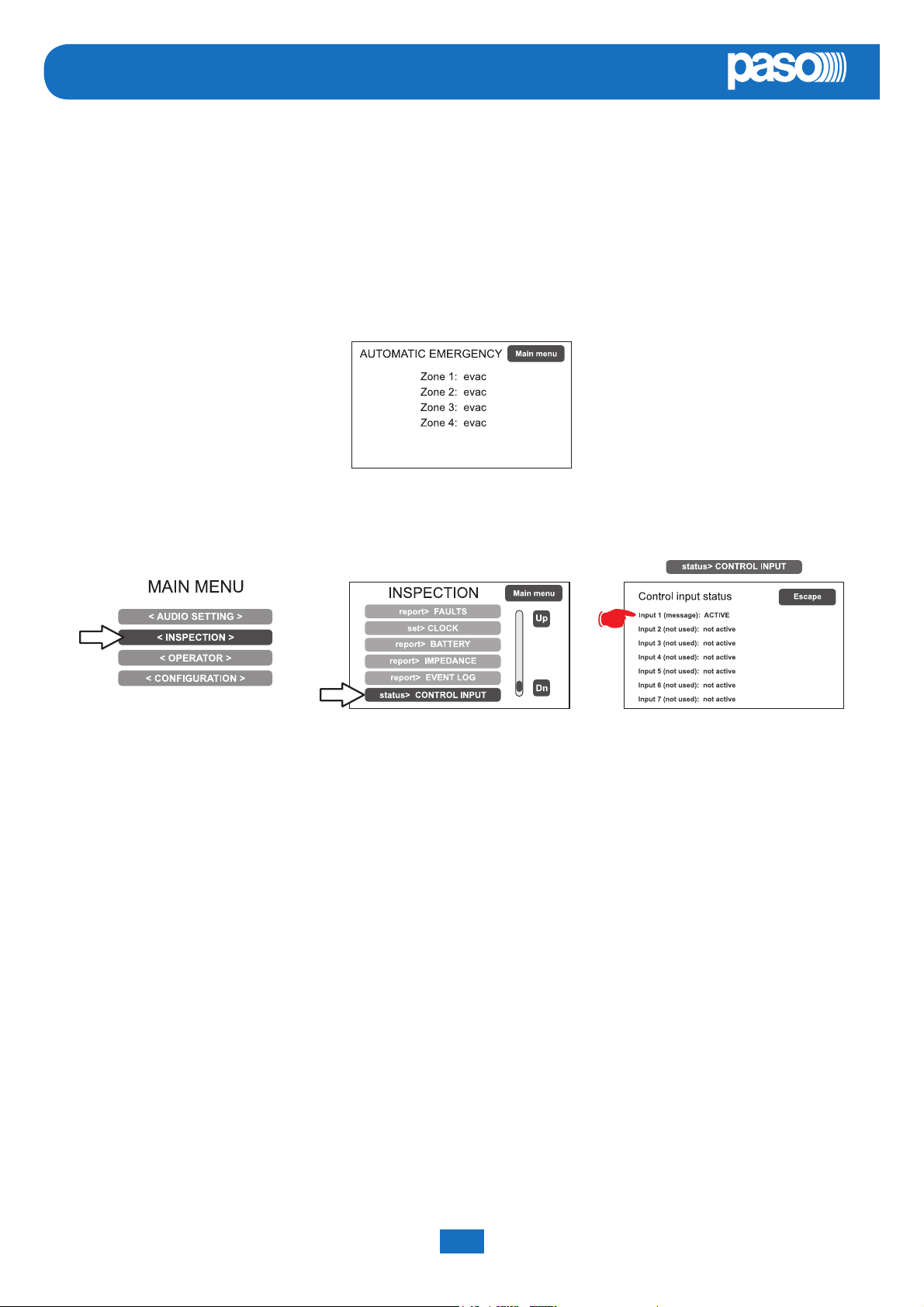
In the event of activation of a programmed input contact the PAW stops its ‘Idle’ state normal activity, mutes the music being
broadcast, inhibits operation of the PA sources for broadcasting announcements and shows the AUTOMATIC EMERGENCY
screen, which indicates the type of message being sent out to the zones:
To see rapidly which input is activating the emergency, press the Main Menu key to return to the main panel, then go to the
INSPECTION menu and select the item status> CONTROL INPUT:
8.9.2 VIEWING THE OPERATIONAL STATUS
The condition of active VOICE ALARM - live announcement via the microphone or pre-recorded message under way - is
shown by the red ALARM LED lighting up on the front panel of the PAW.
8.9.3 SYSTEM OPERATION DURING AN AUTOMATIC EMERGENCY
As long as the input contacts remain active, the MUSIC MENU panel continues to be deactivated, however it is in any case
possible to navigate through the various menus containing options for accessing advanced system functions and to inspect
or change their settings.
The current “Alarm Status” due to the Automatic Emergency can be changed by an authorised operator, who can take steps
to activate the manual controls for managing the system emergency in order to mute the messages by holding the RESET key
down for at least 2 seconds, to change those under way or to send out live announcements with the microphone.
For details concerning the Manual Emergency mode, see the appropriate section (page 44).
8.9.4 EXITING FROM AN AUTOMATIC EMERGENCY
Exit from an Automatic Emergency takes place when no input contact is active.
The system will return to the ‘Idle State’, displaying the MUSIC MENU panel.
PAW5500-VES Compact systems System manual
46
Page 47

PAW5500-VES
EN
9. FAILURE STATUS
THE
PAW5500VES HAS DIAGNOSTIC ROUTINES THAT MONITOR CONTINUOUSLY THE AVAILABILITY OF EMERGENCY
SOURCES AND THE INTEGRITY OF CRITICAL PATHS OF THE SIGNALS ENSURING SYSTEM OPERATION IN EMERGENCY
CONDITIONS.
9.1 SYSTEM OPERATION AND SIGNALLING IN A GENERIC FAILURE CONDITION
• SYSTEM SIGNALLING DUE TO AN EXISTING “FAILURE CONDITION”
When the monitoring system detects a fault during the normal “Idle State” operation, it promptly activates signalling of the
“Failure Condition” as follows:
- the FAULT LED lights up (visual signalling).
- sending out of a beep by the monitor speaker (acoustic signal).
- activation of the local output contacts, if programmed to send signals to an external peripheral unit.
- location of the fault (FAULT): the faulty device and the type of fault are shown on the menu pages under the item
report> FAULTS.
• SYSTEM SIGNALLING FOR RESUMPTION FOLLOWING A “FAILURE CONDITION”
If the cause of the fault no longer exists, the system resumes automatically its “Idle State”, deactivating all the above signalling
and storing the information concerning the last fault. The word RESUMED is shown in the menu pages under the item report>
FAULTS referred to operation of the device that was previously faulty.
• CANCELLING THE ACOUSTIC FAULT SIGNALLING AND OPERATION RESUMPTION SIGNALLING
To cancel the acoustic signalling of a current fault:
- go to the INSPECTION, OPERATOR or CONFIGURATION menus.
- press the RESET button briefl y to halt the beep.
To cancel the signalling of the fault of which a report has been stored and that no longer exists (operation has been RESUMED),
there must be no faults under way or the beep must already have been stopped. Therefore:
- go to the INSPECTION, OPERATOR or CONFIGURATION menus.
- press the RESET button briefl y to reset all the signalling of faults after which operation has been resumed.
Note: In the event of a fault of a loudspeaker line due to a short circuit, once the line has been repaired, it is necessary to
carry out a MANUAL RESET in order to re-activate the audio signal on the output of the concerned line:
- Go to the OPERATOR menu or to the CONFIGURATION menu.
- Select the report> FAULTS menu followed by >>Loudspeaker line. Then, on the ‘Fault zone impedance report’ screen,
press the RESET key and hold it down for at least two seconds
9.2 SYSTEM OPERATION AND SIGNALLING WITH A FAULT ON A LOUDSPEAKER LINE
A fault on a loudspeaker line may be due to any of several causes, such as high impedance, low impedance or a short circuit.
If it is a matter of a change in the impedance, the PAW continues to send out the zone output audio signal. If, on the other hand,
there is a short circuit, the system will disconnect the faulty line of the zone and continue to send out the audio signal on the
other line of the same zone (if this is arranged at the time of installation).
System manual PAW5500-VES Compact systems
47
Page 48

EN
PAW5500-VES
10. TECHNICAL SPECIFICATIONS
MODEL PAW5502-V PAW5504-V PAW5506-V
Rated audio output @230V
*typical distortion at 25 W 0,025%
500 W / D=2,5%*
Rated audio output @24V
typical distortion at 25 W 0,025%
*
Display 4.3” backlit with touch screen 480x272 pixels
N° of PAW5500-VES/x per system Max 6 (ID 0÷5)
N° of zones/amplifi ers 2 4 6
Inputs
Emergency microphone
• Sensitivity / Impedance
• Frequency response
• S/N ratio
Paging units (BROAD.)
• Sensitivity / Impedance
• Frequency response
• S/N ratio
Emergency units (EMERG.)
• Sensitivity / Impedance
• Frequency response
• S/N ratio
AUX (LINE-VOX)
• Sensitivity / Impedance
• Frequency response
• S/N ratio
Balanced XLR-F on the front door
Signal level 20 mV / 10 kΩ
60 ÷20.000 Hz
72 dB
1 off Rj45 for PMB106/112 paging units (PA)
Signal level max. 1400 mV / 85 kΩ
60 ÷20.000 Hz
83 dB
1 off Rj45 for Serie PMB132 or TSB8500-V emergency microphone units
Signal level max. 1400 mV / 85 kΩ
60 ÷20.000 Hz
83 dB
Balanced with terminals (HOT-COM-GND)
Programmable in ON / OFF / VOX with A.P.T. modes
Precedence input with contact closing activation
134 mV / 31 kΩ
90 ÷ 20.000 Hz
81 dB / 85 dBA
400 W / D=10%*
MUSIC / EXT
• Sensitivity / Impedance
• Frequency response
• S/N ratio
Equalisation
Independent equalisation
for each output zone
Independent equalisation
for each music input
Outputs
Constant voltage outputs
With double lines (A/B)
One zone output can be confi gured as a
standby for the others.
REMOTE LINK
• Output level / Impedance
• Sensitivity / Input impedance
Emergency controls
• Controlled inputs CONTACT
• Outputs R1, R2, R3
Balanced with terminals (HOT-COM-GND)
134 mV / 31 kΩ
90 ÷ 20.000 Hz
81 dB / 85 dBA
3-band equaliser
Bass tones (100 Hz): ± 10 dB
Mid-range (1 kHz): ± 10 dB
Treble tones (10 kHz): ± 10 dB
2 zones
for 100V lines
Minimum 40 Ω
n°2+2 Rj45 for connection with another PAW5500-VES unit
1 V / 400 Ω
3600 mV / 3 kΩ
Programmable for normally active or normally inactive state
7 off inputs with diagnostic
3 relays for signalling, state of emergency and faults,
N.O-N.C-Exchange state
4 zones
for 100V lines
Minimum 40 Ω
for 100V lines
Minimum 40 Ω
6 zones
PAW5500-VES Compact systems System manual
48
Page 49

PAW5500-VES
MODEL PAW5502-V PAW5504-V PAW5506-V
General information
Mains power supply @230V
Consumption @230V
230 V 50/60Hz +10/-15%
646 W full load
(2amp active)
36 W no load
230 V 50/60Hz +10/-15%
653 W full load
(2amp active / 2amp stand-by)
47 W no load
230 V 50/60Hz +10/-15%
660 W full load
(2amp active / 4amp stand-by)
Effi ciency: 75,6%
58 W no load
EN
Secondary power supply
20 A full load
20 A full load
@24 V (26,3 V)
Secondary power supply
Consumption @24 V
Batteries
no load / quiescent
0,3 A
no load / energy saving
Suggested value: 26÷28 Ah
It is possible to use other batteries (18 Ah - 33 Ah - 40 Ah / see page 40).
1,22 A
no load / quiescent
0,3 A
no load / energy saving
0,92 A
8 A (I max. a)
Charger / Power supply unit
12 A (I max. b)
21 V (fi nal voltage – detached battery)
27,2 V (complete load voltage)
Environmental operating conditions
Temperature: +5°C ÷ +40°C
Relative humidity: 25% to 75% (non-condensing)
Type of mounting Wall / To 19” rack with ACPAW-RCK optional accessory
Dimensions (L x H x P) 430 x 620 x 240 mm
Net weight (without batteries) 20 kg
20 A full load
1,5 A
no load / quiescent
0,3 A
no load / energy saving
System manual PAW5500-VES Compact systems
49
Page 50
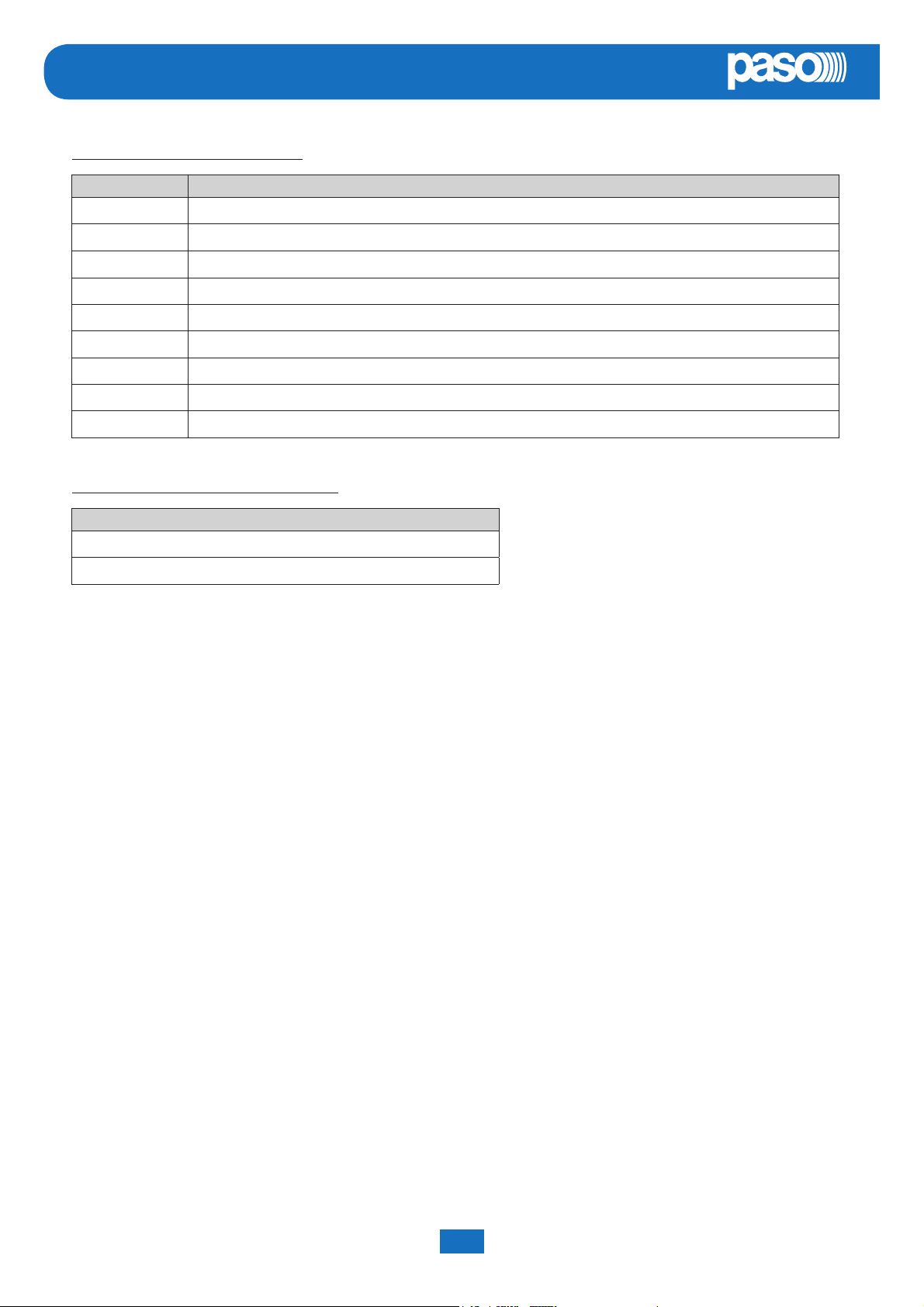
EN
LIST OF OPTIONAL FUNCTIONS
CLAUSE DESCRIPTION
7.6.2 Manual muting of voice alarm condition
7.7.2 Manual resetting of voice alarm condition
7.9 Output for signalling a voice alarm condition
8.3 Indication of fault aff ecting the transmission paths
8.4 Indication of fault aff ecting the alarm zones
10 Manual control of voice alarms
11 Interface for external control device(s)
12 Emergency microphone(s)
13.14 Redundant power amplifi er
LIST OF THE AUXILIARY FUNCTIONS
DESCRIPTION
Broadcast calls
PAW5500-VES
Background music
PAW5500-VES Compact systems System manual
50
Page 51

Page 52

0068
PASO S.p.A.
Via Settembrini, 34 - 20020 Lainate (MI) - ITALIA
18
0068/CPR/101-2018
EN54-4:1997 + A1:2002 + A2:2006
EN 54-16:2008
Voice alarm control and indicated equipment for fi re detection
and fi re alarm systems for buildings
PAW5502-V | PAW5504-V | PAW5506-V
Provided options:
7.6.2 Manual silencing of the voice alarm condition
7.7.2 Manual reset of the voice alarm condition
7.9 Voice alarm condition output
8.3 Indication of fault related to the transmission path to the CIE
8.4 Indication of fault related to voice alarm zone
10 Voice alarm manual control
11 Interface to external control device(s)
12 Emergency microphone(s)
13.14 Redundant power amplifi er
S.p.A.
Via Settembrini, 34 - 20020 Lainate (MI) - Italia
Tel. +39 0258077.1 • Fax +39 0258077.277
http://www.paso.it E-mail: [email protected]
UDT 06/18 | 11/826 | EN
 Loading...