


S.p.A.
Via Mecenate, 90 20138 Milano - Italy Tel. +39 0258077.1 (15 lines) Fax +39 0258077.277
e-mail: info@paso.it - http://www.paso.it
C O N TA C T I TA L I A • To
K U 1 . 4 0 E U G O L ATA C
T S I L A I C E P S S M E T S Y S D N U O S
CATALOGUE 04.1 UK
S O U N D S Y S T E M S S P E C I A L I S T

company presentation
systems
amplifiers
sound sources
microphones and microphone stands
wireless microphones
mobile systems
speaker units

SPECIALISTIOUND SY
PASOLa PASO.P.AS.Pis.Acertified., Aziendafor conformityertificata withEN ISOEN
ISO9001:2000,9001:2000possiede. The knowun know-how-howof design,progettuale,plant-
engineering and industrial experience matured in impiantistico ed industriale maturato in oltre 70 anni over 70 years of activity and consolidated thanks to di attività e consolidatosi attraverso una costante a constant quest for innovation through technology. ricerca dell’innovazione attraverso la tecnologia.
The Company’s precious heritage of technical
Un prezioso bagaglio di tecnica, di competenza knowledge, skill and experience has led it to enjoy
trusted esperienzaand appreciationhe ha inconsentitothe mainallaworldSocietàmarketsdi ongoderewhichdellait is presentfiducia alsoe dell’apprezzamentothrough its subsidiariesdei
PASOprincipaliSoundmercatiProductsmondiali,Inc. (ineithequaliUnitedè presenteStates)
and PASO UK Ltd. (in Great Britain).
anche attraverso le proprie Consociate PASO
Sound Products Inc. (Stati Uniti) e PASO UK Ltd.
PASO is one of the few enterprises in this field
(Gran Bretagna).
able to boast their own original in-house design, industrialisation and manufacturing system for a
La PASO è una delle poche aziende del settore che full range of products, from the most complex
andpuò vantaresophisticatedun proprioequipmentsistema intoegratothe disimplexprogetaccessoriestazione originale,. industrializzazione e fabbricazio-

STEMDEI SISTEMISPECIALISTSONORI
Thisne peris nounaccidentgammalcomplchoice.taItdiis aprodotti,choice ofchequalityspaziaanddallegreatappareccom--
mitment,chiature thankspiù complesseto which eoursofisticateCompanyaglialsoaccessorioperates piùas ansempliciactive. partner for Customers in every design and application-related
aspect of their sound-broadcasting systems.
È una scelta non casuale, di qualità e di grande impegno, che vede
anche operare l’Azienda quale Partner attivo del Cliente per tutti gli
In addition to being a mark of the Company’s constant commitment, aspetti progettuali ed applicativi dell’impianto di sonorizzazione. this new catalogue, which includes some totally innovative product
lines, is also intended as a useful guide for design firms, installers, techniciansQuesto nuovoandcatalogo,specialists,chetocomhelprendethem lineedesigndiandprodottocreatetotalmensound--
amplificte innovationve, systemsvuole essere,of everyoltretypecheandil segnodegreelofcostantecomplexityimpegno.
della Società, uno strumento utile a Studi di progettazione, Aziende
To complete the information provided in the catalogue, detailed di installazione, Tecnici e Specialisti, per il disegno e la realizzaziotechnical sheets, application diagrams and user guides for the most ne di sistemi di amplificazione sonora di ogni tipo e complessità. important products are available, on entering your password, at
the site www.paso.it
Ad integrazione delle informazioni qui contenute, schede tecniche dettagliate, schemi applicativi e manuali
d’uso dei principali prodotti sono reperibili, tramite password, nel sito www.paso.it

Table of contents
systems
• P M S 2 0 0 0 P R O F E S S I O N A L M O D U L A R S Y S T E M . . . . . . . . . . . . . . . . . . . . . . . . . . . . . . . . . . . . . . . . . . . . . . . . . . . . . . . . . . . . . . . . . . . . . . . . . . . . . . . . . . . . . |
1 . 1 |
• E X A M P L E S O F A P P L I C A T I O N S . . . . . . . . . . . . . . . . . . . . . . . . . . . . . . . . . . . . . . . . . . . . . . . . . . . . . . . . . . . . . . . . . . . . . . . . . . . . . . . . . . . . . . . . . . . . . . . . . . . . . . . . . . . . . . . . . . . . . . . . . . . . . . . . . . . . . . . . |
1 . 1 6 |
• P 8 0 3 6 - 6 Z O N E V O I C E / M U S I C S W I T C H I N G U N I T . . . . . . . . . . . . . . . . . . . . . . . . . . . . . . . . . . . . . . . . . . . . . . . . . . . . . . . . . . . . . . . . . . . . . |
1 . 2 0 |
• S D 2 0 0 M U L T I - C H A N N E L D I S T R I B U T I O N S Y S T E M . . . . . . . . . . . . . . . . . . . . . . . . . . . . . . . . . . . . . . . . . . . . . . . . . . . . . . . . . . . . . . . . . . . . . . . . . . . . . |
1 . 21 |
• I T C 2 0 0 0 - C I N T E R P H O N E S Y S T E M F O R C O U N T E R S . . . . . . . . . . . . . . . . . . . . . . . . . . . . . . . . . . . . . . . . . . . . . . . . . . . . . . . . . . . . . . . . . . . . . . . |
1 . 2 3 |
• R A C K - T Y P E C A B I N E T S 5 8 0 0 - D R A N G E . . . . . . . . . . . . . . . . . . . . . . . . . . . . . . . . . . . . . . . . . . . . . . . . . . . . . . . . . . . . . . . . . . . . . . . . . . . . . . . . . . . . . . . . . . . . . . . . . . . . . . . . . . . . . . . . . . . . . |
1 . 2 4 |
• C O M P L E T E S E R V I C E P A N E L S F O R R A C K M O U N T I N G . . . . . . . . . . . . . . . . . . . . . . . . . . . . . . . . . . . . . . . . . . . . . . . . . . . . . . . . . . . . . . . . . |
1 . 2 5 |
amplifiers
• 8 0 0 0 R A N G E I N T E G R A T E D A M P L I F I E R S . . . . . . . . . . . . . . . . . . . . . . . . . . . . . . . . . . . . . . . . . . . . . . . . . . . . . . . . . . . . . . . . . . . . . . . . . . . . . . . . . . . . . . . . . . . . . . . . . . . . . . . . . |
2 . 1 |
• 8 0 0 0 R A N G E B O O S T E R U N I T S . . . . . . . . . . . . . . . . . . . . . . . . . . . . . . . . . . . . . . . . . . . . . . . . . . . . . . . . . . . . . . . . . . . . . . . . . . . . . . . . . . . . . . . . . . . . . . . . . . . . . . . . . . . . . . . . . . . . . . . . . . . . . . . . . . . . |
2 . 2 |
• 8 0 0 0 R A N G E I N T E R N A L M O D U L E S . . . . . . . . . . . . . . . . . . . . . . . . . . . . . . . . . . . . . . . . . . . . . . . . . . . . . . . . . . . . . . . . . . . . . . . . . . . . . . . . . . . . . . . . . . . . . . . . . . . . . . . . . . . . . . . . . . . . . . |
2 . 4 |
• 8 0 0 0 R A N G E E X T E R N A L M O D U L E S . . . . . . . . . . . . . . . . . . . . . . . . . . . . . . . . . . . . . . . . . . . . . . . . . . . . . . . . . . . . . . . . . . . . . . . . . . . . . . . . . . . . . . . . . . . . . . . . . . . . . . . . . . . . . . . . . . . . . . . |
2 . 4 |
• 8 0 0 0 R A N G E P 8 0 0 6 S Y S T E M C O N T R O L . . . . . . . . . . . . . . . . . . . . . . . . . . . . . . . . . . . . . . . . . . . . . . . . . . . . . . . . . . . . . . . . . . . . . . . . . . . . . . . . . . . . . . . . . . . . . . . . . . . . . . . |
2 . 7 |
• 8 0 0 0 R A N G E M I X E R S . . . . . . . . . . . . . . . . . . . . . . . . . . . . . . . . . . . . . . . . . . . . . . . . . . . . . . . . . . . . . . . . . . . . . . . . . . . . . . . . . . . . . . . . . . . . . . . . . . . . . . . . . . . . . . . . . . . . . . . . . . . . . . . . . . . . . . . . . . . . . . . . . . . . . . . . . . . . . . . . |
2 . 9 |
• 8 0 0 0 R A N G E P 8 0 2 3 G R A P H I C E Q U A L I Z E R . . . . . . . . . . . . . . . . . . . . . . . . . . . . . . . . . . . . . . . . . . . . . . . . . . . . . . . . . . . . . . . . . . . . . . . . . . . . . . . . . . . . . . . . . . . . . . |
2 . 12 |
• 8 0 0 0 R A N G E P 8 0 2 4 - B F E E D B A C K C O N T R O L L E R . . . . . . . . . . . . . . . . . . . . . . . . . . . . . . . . . . . . . . . . . . . . . . . . . . . . . . . . . . . . . . . . . . . . . . . . . . . . . . |
2 . 1 3 |
• 5 0 0 0 R A N G E 2 3 0 V A C , 2 4 V D C I N T E G R A T E D A M P L I F I E R S . . . . . . . . . . . . . . . . . . . . . . . . . . . . . . . . . . . . . . . . . . . . . . |
2 . 1 4 |
• 5 0 0 0 R A N G E B O O S T E R U N I T S . . . . . . . . . . . . . . . . . . . . . . . . . . . . . . . . . . . . . . . . . . . . . . . . . . . . . . . . . . . . . . . . . . . . . . . . . . . . . . . . . . . . . . . . . . . . . . . . . . . . . . . . . . . . . . . . . . . . . . . . . . . . . . . . . . . . |
2 . 1 5 |
• 5 0 0 0 R A N G E A M P L I F I E R S A N D B O O S T E R U N I T S - S P E C I A L F E A T U R E S . . . . . . . . . . |
2 . 1 5 |
• 3 3 0 0 R A N G E 2 3 0 V A C 12 / 2 4 V D C I N T E G R A T E D A M P L I F I E R S . . . . . . . . . . . . . . . . . . . . . . . . . . . . . . . . . . . . |
2 . 17 |
• A U T O M A T I C L E V E L C O N T R O L L E R . . . . . . . . . . . . . . . . . . . . . . . . . . . . . . . . . . . . . . . . . . . . . . . . . . . . . . . . . . . . . . . . . . . . . . . . . . . . . . . . . . . . . . . . . . . . . . . . . . . . . . . . . . . . . . . . . . . . . . . . . . . . . . |
2 . 1 8 |
• I N D U S T R I A L A M P L I F I E R . . . . . . . . . . . . . . . . . . . . . . . . . . . . . . . . . . . . . . . . . . . . . . . . . . . . . . . . . . . . . . . . . . . . . . . . . . . . . . . . . . . . . . . . . . . . . . . . . . . . . . . . . . . . . . . . . . . . . . . . . . . . . . . . . . . . . . . . . . . . . . . . . . . . . . . . . . . |
2 . 2 0 |
• L A X C U R R E N T A M P L I F I E R S . . . . . . . . . . . . . . . . . . . . . . . . . . . . . . . . . . . . . . . . . . . . . . . . . . . . . . . . . . . . . . . . . . . . . . . . . . . . . . . . . . . . . . . . . . . . . . . . . . . . . . . . . . . . . . . . . . . . . . . . . . . . . . . . . . . . . . . . . . . . . . . . . . |
2 . 21 |
sound sources
• C O M P A C T S Y S T E M S . . . . . . . . . . . . . . . . . . . . . . . . . . . . . . . . . . . . . . . . . . . . . . . . . . . . . . . . . . . . . . . . . . . . . . . . . . . . . . . . . . . . . . . . . . . . . . . . . . . . . . . . . . . . . . . . . . . . . . . . . . . . . . . . . . . . . . . . . . . . . . . . . . . . . . . . . . . . . . . . . . . . . |
3 . 1 |
• P R O G R A M G E N E R A T O R S . . . . . . . . . . . . . . . . . . . . . . . . . . . . . . . . . . . . . . . . . . . . . . . . . . . . . . . . . . . . . . . . . . . . . . . . . . . . . . . . . . . . . . . . . . . . . . . . . . . . . . . . . . . . . . . . . . . . . . . . . . . . . . . . . . . . . . . . . . . . . . . . . . . . . . . |
3 . 3 |
• T A P E - T U N E R - C D . . . . . . . . . . . . . . . . . . . . . . . . . . . . . . . . . . . . . . . . . . . . . . . . . . . . . . . . . . . . . . . . . . . . . . . . . . . . . . . . . . . . . . . . . . . . . . . . . . . . . . . . . . . . . . . . . . . . . . . . . . . . . . . . . . . . . . . . . . . . . . . . . . . . . . . . . . . . . . . . . . . . . . . . . |
3 . 5 |
microphones and microphone stands
• D Y N A M I C M I C R O P H O N E S . . . . . . . . . . . . . . . . . . . . . . . . . . . . . . . . . . . . . . . . . . . . . . . . . . . . . . . . . . . . . . . . . . . . . . . . . . . . . . . . . . . . . . . . . . . . . . . . . . . . . . . . . . . . . . . . . . . . . . . . . . . . . . . . . . . . . . . . . . . . . . . . . . |
4 . 1 |
• E L E C T R E T M I C R O P H O N E S . . . . . . . . . . . . . . . . . . . . . . . . . . . . . . . . . . . . . . . . . . . . . . . . . . . . . . . . . . . . . . . . . . . . . . . . . . . . . . . . . . . . . . . . . . . . . . . . . . . . . . . . . . . . . . . . . . . . . . . . . . . . . . . . . . . . . . . . . . . . . . . . . . . |
4 . 2 |
• A C C E S S O R I E S . . . . . . . . . . . . . . . . . . . . . . . . . . . . . . . . . . . . . . . . . . . . . . . . . . . . . . . . . . . . . . . . . . . . . . . . . . . . . . . . . . . . . . . . . . . . . . . . . . . . . . . . . . . . . . . . . . . . . . . . . . . . . . . . . . . . . . . . . . . . . . . . . . . . . . . . . . . . . . . . . . . . . . . . . . . . . . . . . . . . . |
4 . 3 |
• B 5 0 1 - M M I C R O P H O N E C O N S O L E . . . . . . . . . . . . . . . . . . . . . . . . . . . . . . . . . . . . . . . . . . . . . . . . . . . . . . . . . . . . . . . . . . . . . . . . . . . . . . . . . . . . . . . . . . . . . . . . . . . . . . . . . . . . . . . . . . . . . . . . . . . |
4 . 4 |
• M I C R O P H O N E S F O R S P E C I A L A P P L I C A T I O N S . . . . . . . . . . . . . . . . . . . . . . . . . . . . . . . . . . . . . . . . . . . . . . . . . . . . . . . . . . . . . . . . . . . . . . . . . . . . . . . . . . . . . . . |
4 . 5 |
• B 6 0 0 M I C R O P H O N E S C O N S O L E S . . . . . . . . . . . . . . . . . . . . . . . . . . . . . . . . . . . . . . . . . . . . . . . . . . . . . . . . . . . . . . . . . . . . . . . . . . . . . . . . . . . . . . . . . . . . . . . . . . . . . . . . . . . . . . . . . . . . . . . . . . |
4 . 6 |
• C O N N E C T I O N C A B L E S F O R M I C R O P H O N E S A N D C O N S O L E S . . . . . . . . . . . . . . . . . . . . . . . . . . . . . . . . . . . . . . . . . . . . . . . . . . . . . . . . . . . . . |
4 . 7 |
• B 5 0 0 M I C R O P H O N E C O N S O L E S . . . . . . . . . . . . . . . . . . . . . . . . . . . . . . . . . . . . . . . . . . . . . . . . . . . . . . . . . . . . . . . . . . . . . . . . . . . . . . . . . . . . . . . . . . . . . . . . . . . . . . . . . . . . . . . . . . . . . . . . . . . . . . |
4 . 8 |
• C O M PAT I B I L I T Y B E T W E E N PA S O M I C R O P H O N E C O N S O L E S A N D A M P L I F I E R S . . . . . . . |
4 . 9 |

Table of contents
wireless microphones
• H A N D - H E L D A N D P O C K E T M I C R O P H O N E S . . . . . . . . . . . . . . . . . . . . . . . . . . . . . . . . . . . . . . . . . . . . . . . . . . . . . . . . . . . . . . . . . . . . . . . . . . . . . . . . . . . . . . . . . . . . . . . |
5 . 1 |
• S I N G L E - C H A N N E L R E C E I V E R S . . . . . . . . . . . . . . . . . . . . . . . . . . . . . . . . . . . . . . . . . . . . . . . . . . . . . . . . . . . . . . . . . . . . . . . . . . . . . . . . . . . . . . . . . . . . . . . . . . . . . . . . . . . . . . . . . . . . . . . . . . . . . . . . . . . . . . . |
5 . 2 |
• M U L T I P L E S Y S T E M . . . . . . . . . . . . . . . . . . . . . . . . . . . . . . . . . . . . . . . . . . . . . . . . . . . . . . . . . . . . . . . . . . . . . . . . . . . . . . . . . . . . . . . . . . . . . . . . . . . . . . . . . . . . . . . . . . . . . . . . . . . . . . . . . . . . . . . . . . . . . . . . . . . . . . . . . . . . . . . . . . . . . . . . . . . . |
5 . 3 |
• V H F / U H F W I R E L E S S M I C R O P H O N E K I T . . . . . . . . . . . . . . . . . . . . . . . . . . . . . . . . . . . . . . . . . . . . . . . . . . . . . . . . . . . . . . . . . . . . . . . . . . . . . . . . . . . . . . . . . . . . . . . . . . . . . . . . . . |
5 . 4 |
mobile systems
• 1 0 0 0 R A N G E . . . . . . . . . . . . . . . . . . . . . . . . . . . . . . . . . . . . . . . . . . . . . . . . . . . . . . . . . . . . . . . . . . . . . . . . . . . . . . . . . . . . . . . . . . . . . . . . . . . . . . . . . . . . . . . . . . . . . . . . . . . . . . . . . . . . . . . . . . . . . . . . . . . . . . . . . . . . . . . . . . . . . . . . . . . . . . . . . . . . . . . . . . |
6 . 1 |
• A C C E S S O R I E S F O R 1 0 0 0 R A N G E . . . . . . . . . . . . . . . . . . . . . . . . . . . . . . . . . . . . . . . . . . . . . . . . . . . . . . . . . . . . . . . . . . . . . . . . . . . . . . . . . . . . . . . . . . . . . . . . . . . . . . . . . . . . . . . . . . . . . . . . . . . . |
6 . 2 |
• C O M P A C T S Y S T E M S . . . . . . . . . . . . . . . . . . . . . . . . . . . . . . . . . . . . . . . . . . . . . . . . . . . . . . . . . . . . . . . . . . . . . . . . . . . . . . . . . . . . . . . . . . . . . . . . . . . . . . . . . . . . . . . . . . . . . . . . . . . . . . . . . . . . . . . . . . . . . . . . . . . . . . . . . . . . . . . . . . . . . |
6 . 2 |
• P O R T A B L E A M P L I F I E D S Y S T E M . . . . . . . . . . . . . . . . . . . . . . . . . . . . . . . . . . . . . . . . . . . . . . . . . . . . . . . . . . . . . . . . . . . . . . . . . . . . . . . . . . . . . . . . . . . . . . . . . . . . . . . . . . . . . . . . . . . . . . . . . . . . . . . . . . . . . . |
6 . 4 |
• M E G A P H O N E S . . . . . . . . . . . . . . . . . . . . . . . . . . . . . . . . . . . . . . . . . . . . . . . . . . . . . . . . . . . . . . . . . . . . . . . . . . . . . . . . . . . . . . . . . . . . . . . . . . . . . . . . . . . . . . . . . . . . . . . . . . . . . . . . . . . . . . . . . . . . . . . . . . . . . . . . . . . . . . . . . . . . . . . . . . . . . . . . . . . . . . |
6 . 4 |
• A M P L I F I E D L E C T E R N . . . . . . . . . . . . . . . . . . . . . . . . . . . . . . . . . . . . . . . . . . . . . . . . . . . . . . . . . . . . . . . . . . . . . . . . . . . . . . . . . . . . . . . . . . . . . . . . . . . . . . . . . . . . . . . . . . . . . . . . . . . . . . . . . . . . . . . . . . . . . . . . . . . . . . . . . . . . . . . . . . . . |
6 . 5 |
speaker units
• “ S L I M L I N E ” 4 0 0 R A N G E S O U N D C O L U M N S . . . . . . . . . . . . . . . . . . . . . . . . . . . . . . . . . . . . . . . . . . . . . . . . . . . . . . . . . . . . . . . . . . . . . . . . . . . . . . . . . . . . . . . . |
7. 1 |
• 5 0 0 R A N G E S O U N D C O L U M N S . . . . . . . . . . . . . . . . . . . . . . . . . . . . . . . . . . . . . . . . . . . . . . . . . . . . . . . . . . . . . . . . . . . . . . . . . . . . . . . . . . . . . . . . . . . . . . . . . . . . . . . . . . . . . . . . . . . . . . . . . . . . . . . . . |
7. 2 |
• W A L N U T S O U N D C O L U M N S . . . . . . . . . . . . . . . . . . . . . . . . . . . . . . . . . . . . . . . . . . . . . . . . . . . . . . . . . . . . . . . . . . . . . . . . . . . . . . . . . . . . . . . . . . . . . . . . . . . . . . . . . . . . . . . . . . . . . . . . . . . . . . . |
7. 4 |
• S O U N D P R O J E C T O R S . . . . . . . . . . . . . . . . . . . . . . . . . . . . . . . . . . . . . . . . . . . . . . . . . . . . . . . . . . . . . . . . . . . . . . . . . . . . . . . . . . . . . . . . . . . . . . . . . . . . . . . . . . . . . . . . . . . . . . . . . . . . . . . . . . . . . . . . . . . . . . . . . . . . . . . . . . . . . . . . . |
7. 4 |
• S P E A K E R U N I T S F O R W A L L A N D C E I L I N G - M O U N T I N G . . . . . . . . . . . . . . . . . . . . . . . . . . . . . . . . . . . . . . . . . . . . . . . . . . . . . . . . . . |
7. 6 |
• C A B I N E T - M O U N T E D S P E A K E R U N I T S . . . . . . . . . . . . . . . . . . . . . . . . . . . . . . . . . . . . . . . . . . . . . . . . . . . . . . . . . . . . . . . . . . . . . . . . . . . . . . . . . . . . . . . . . . . . . . . . . . . . . . . . . . . . . . . . . |
7. 12 |
• P R O S O U N D S P E A K E R U N I T S . . . . . . . . . . . . . . . . . . . . . . . . . . . . . . . . . . . . . . . . . . . . . . . . . . . . . . . . . . . . . . . . . . . . . . . . . . . . . . . . . . . . . . . . . . . . . . . . . . . . . . . . . . . . . . . . . . . . . . . . . . . . . . . . . . . . . . . . . . . |
7. 1 5 |
• E X P O N E N T I A L H O R N S W I T H S E P A R A T E D R I V E U N I T S . . . . . . . . . . . . . . . . . . . . . . . . . . . . . . . . . . . . . . . . . . . . . . . . . . . . . . . . . . . . . . . |
7. 17 |
• S I N C R O M I X L O N G - R A N G E M U L T I P L E H O R N . . . . . . . . . . . . . . . . . . . . . . . . . . . . . . . . . . . . . . . . . . . . . . . . . . . . . . . . . . . . . . . . . . . . . . . . . . . . . . . . . . . . . . . . |
7. 17 |
• A L U M I N I U M H O R N S C O M P L E T E W I T H D R I V E U N I T S W E A . . . . .T H E R - P R O O F V E R S I O N 7. 1 8 |
|
• E X T E N D E D - R A N G E T W O - W A Y H O R N . . . . . . . . . . . . . . . . . . . . . . . . . . . . . . . . . . . . . . . . . . . . . . . . . . . . . . . . . . . . . . . . . . . . . . . . . . . . . . . . . . . . . . . . . . . . . . . . . . . . . . . . . . . . . . . . . . . |
7. 1 9 |
• A C C E S S O R I E S F O R S P E A K E R U N I T S . . . . . . . . . . . . . . . . . . . . . . . . . . . . . . . . . . . . . . . . . . . . . . . . . . . . . . . . . . . . . . . . . . . . . . . . . . . . . . . . . . . . . . . . . . . . . . . . . . . . . . . . . . . . . . . . . . . . |
7. 2 0 |
. . . . . . . . . . . . . . . . . . . . . . . . . . . . . . . . . . . . . . . . . . . . . . . . . . . . . . . . . . . . . . . . . . . . . . . . . . . . . . . . . . . . . . . . . . . . . . . . . . . . . . . . . . . . . . . . . . . . . . . . . . . . . . . . . . . . . . . . . . . . . . . . . . . . . . . . . . . . . . . . . . . . . . . . . . . . . . . . . . . . . . . . . . . . . . . . . . . . . . . . . . . . . . .• I N D E X |
8 . 1 |
|
|
PASO S.p.A., in its policy of continuous improvement, reserves the right to make modifications without prior notice.

systems
PMS2000 SYSTEM
SOUND INSTALLATIONS, PARTICULARLY IF THEY ARE COMPLEX AND REQUIRE HIGH LEV-
ELS OF SAFETY AND FLEXIBILITY, MUST BE SUPPLEMENTED, INCREASINGLY FREQUENTLY,
BY SOPHISTICATED MANAGEMENT AND DIAGNOSTIC SYSTEMS FOR THE VARIOUS COM-
PONENTS AND CONTROL SYSTEMS FOR THE LINES, POWER SUPPLIES AND AMPLIFIERS.
THEY MUST FEATURE FLEXIBLE SELECTION OF THE INPUTS AND OUTPUTS AND FLEXIBLE
INTERFACING WITH EXTERNAL PERIPHERAL UNITS. THE PASO PMS2000 SYSTEM IS
AVAILABLE FOR THESE APPLICATIONS AND OTHER MORE DEMANDING ONES. IT IS AN
EXTREMELY VERSATILE PROFESSIONAL MODULAR AMPLIFICATION “SYSTEM” CAPABLE
OF MEETING THE MOST COMPLEX PLANT SPECIFICATIONS.
SOUND DISTRIBUTION SYSTEMS
AN ESSENTIAL AND QUALIFYING FEATURE OF ANY HOTEL, TOURIST FACILITY, RESI-
DENCE OR HOSPITAL IS AN EFFECTIVE SYSTEM FOR DISTRIBUTING MORE THAN ONE
SOUND PROGRAMME TO EACH ROOM OR COMMON AREA, THROUGH COMPACT
AND AESTHETICALLY PLEASING RECEIVER UNITS. THE POSSIBILITY OF USING THE SYS-
TEM TO BROADCAST GENERAL OR ALARM ANNOUNCEMENTS THAT CAN BE ACTIVAT-
ED EVEN WHEN THE RECEIVERS ARE SWITCHED OFF ADDS VALUE AND USEFULNESS TO
THE SYSTEM. PASO MULTI-CHANNEL SYSTEMS BASED ON TELEPHONE PAIRS ARE THE
SIMPLEST, MOST INEXPENSIVE AND MOST RATIONAL PLANT-ENGINEERING SYSTEM
FOR DISTRIBUTING MORE THAN ONE AUDIO PROGRAMME THROUGHOUT STRUC-
TURES THAT ARE COMPLEX IN ANY WAY, WITH NO LIMIT TO THE NUMBER OF LISTEN-
ING STATIONS AND WITH THE POSSIBILITY OF “LOCAL” RECEIVER CUSTOMISATION.
MULTI-CHANNEL DISTRIBUTION CAN ALSO BE PUT TO GOOD USE IN SIMPLE AND
RELIABLE WIRED SIMULTANEOUS TRANSLATION SYSTEMS.
systems
PMS2000 • Professional modular system
P M S 2 0 0 0
THE PMS2000 SYSTEM WAS DEVEL-
OPED WITH THE AIM OF CREATING BOTH CONVENTIONAL BROADCASTING SYSTEMS FEATURING FLEXIBILITY OF USE AND THE POSSIBILITY OF ADDING TO THEM IN TIME, AND SOUND-BROADCASTING SYSTEMS WITH DIAGNOSTIC CONTROL INCLUDING A FUNCTION FOR SENDING EMERGENCY OR EVACUATION MESSAGES (VOICE EVACUATION SYSTEMS – VES), MEETING IEC 60849 STANDARDS. THE MODULAR NATURE OF THE SYSTEM ENABLES TAILOR-MADE CONFIGURATIONS TO BE CREATED, WITH REGARD BOTH TO DESIGN SPECIFICATIONS AND THE BUDGET AT DISPOSAL. IN DESIGNING A VES SYSTEM, IT IS NECESSARY TO COMPLY NOT ONLY WITH THE INDICATIONS PROVIDED BELOW BUT ALSO WITH IEC
60849 STANDARDS MENTIONED ABOVE.
GENERAL FEATURES
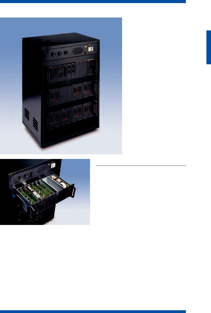
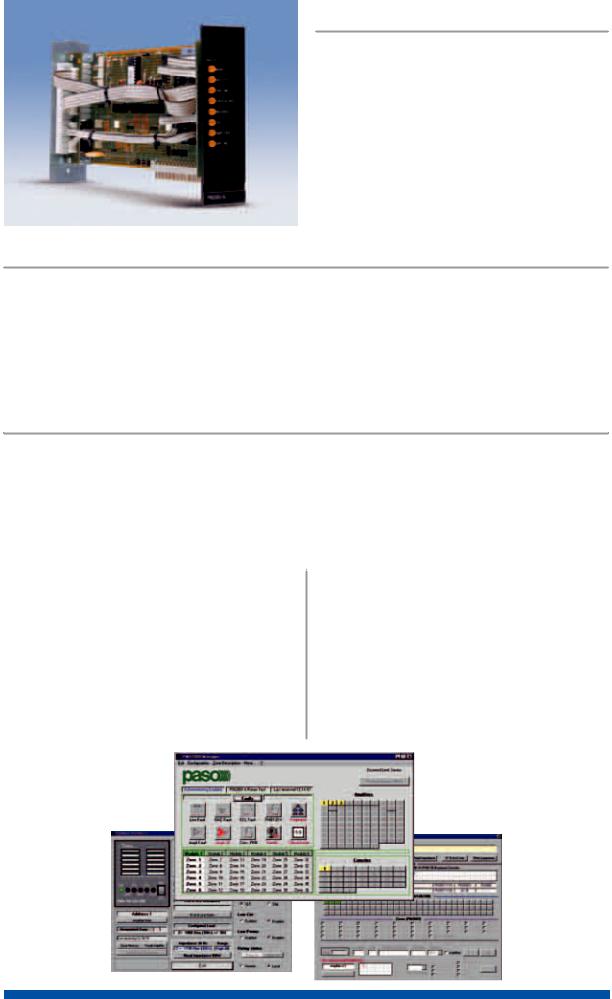
The modular PMS 2000 system uses two types of card-cage:
a signal card-cage, in which up to a maximum of 10
modules can be housed, and a power card-cage, capa-
ble of containing from two to four amplifiers, depending on
their output power. The PMS2002-B card-cage will contain
the modules (input/output modules, zones selectors, line out-
put, power supplies, tuners, etc.) that, thanks to the bus-type
configuration of the mother board, can be plugged in with-
out having to follow a specific order. This is because an
essential and innovative feature of the PMS2000 system is the
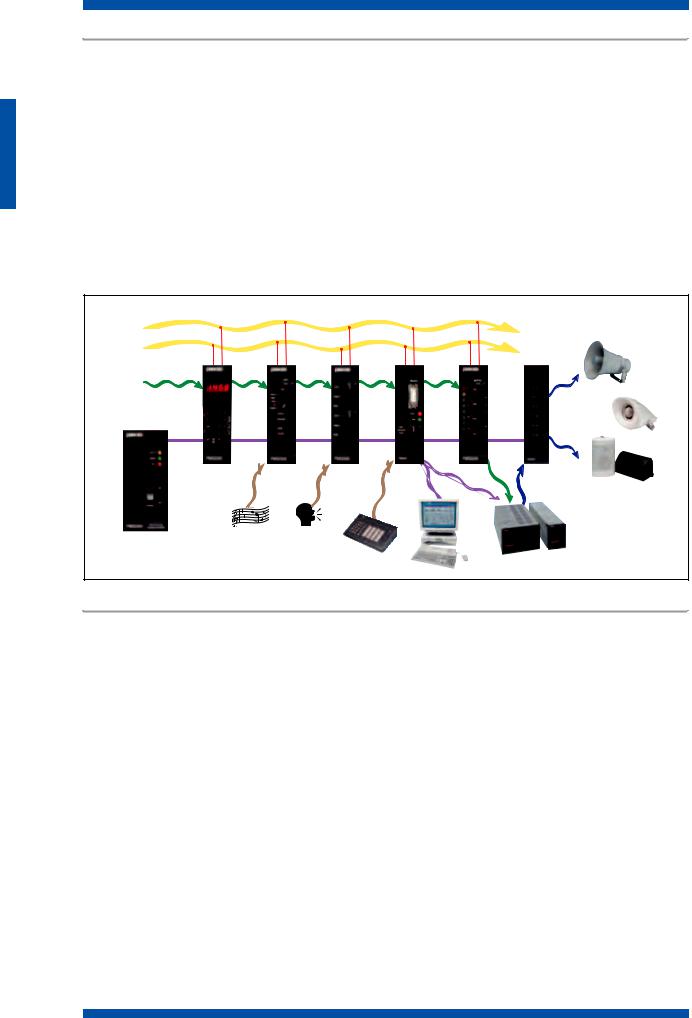
 presence of 3 signal buses, of which one for managing PA P M S 2 0 0 2 - B signals with related zones addressing and two (A & B) for
  managing two signals other than PA or one stereo signal (fig. 1.1). This enables several independent systems to be set up within a single card-cage, in which they will in any case be connected to a single control and power-supply line. One example of application could be that of a theatre in which it would be possible, using a single system, to broadcast stereo music for the show and, at the same time, to make voice calls to the single dressing-rooms. In case of need or in an emergency, it would be possible to suspend the music to send general messages to all the rooms. The bus carries the power-supply lines, the audio signals, the serial communication line and the service signals (priority, enabling, etc.). The only exception to the random nature of the positions of the modules inside the rack concerns the PM2020-B and PM2020-V input modules, for which priority of the inputs on one card over those on another is defined by the position of the card in question within the card-cage. The signal card-cage is mounted on sliding guides that enable it to be pulled out from the rack. Once the card-cage has been pulled out, the card-cage can be rotated for ease of installation and maintenance of the modules. The modules are plugged into the card-cage with no need for any internal cabling. All the connectors used for the input and output connections, located on the rear, are of the professional type and particularly functional (XLR inputs with locking levers, removable screw-down terminal with bayonet couplings, etc). A PMS2000 system can include up to three PMS2002-B card-cages. Each card-cage can house up to 9 standard 38 mm wide
modules plus one PM2011-B power-supply module.
The PMS2001 power card-cage enables power amplifiers to be installed in a rack. Three models of amplifier are available, with outputs of 240 W (PMW240), 120 W (PMW 120) and 60 W (PMW60) respectively. A card-cage can contain up to four 60 W or 120 W amplifiers or two 240 W amplifiers, since the latter take up twice as much room in front. Various combinations are possible, such as two 120 W amplifiers plus one 240 W amplifier.
S Y S T E M S
1.1
A - P M S 2 0 0 0 S Y S T E M S F O R S O U N D - B R O A D C A S T I N G O N L Y
By combining the various functional modules and call stations at disposal, it is possible to “compose” systems for broadcasting music and announcements, the functional characteristics of which may include:
•Up to 16 audio inputs with adjustable sensitivity for each channel for a system with only one signal card-cage
•Up to 48 audio signals for a system with 3 signal card-cages
•Up to 32 or 36 output zones, with override control
•Up to 32 levels of priority among the inputs
•Several independent audio systems in the same rack
•Integration with outside units (matrix units, message generators, PABXs, etc.)
•230 VAC and/or 24 VDC power-supply
•12, 24 or 32-zone call stations with star connections
•Programmable digital call stations on RS485 serial lines.
Use of analogue call stations is advisable in systems in which the financial aspect prevails, while digital keypads are used in PA systems in which specific functions are required, such as control of the system directly from the call station (volume control, selection of radio stations, intercommunications between the call stations, etc.). When using digital microphone stands, it is essential to use the SWPMB1.0 configuration system.
B U S
A
B
PA
S Y S T E M S
PM2060-B |
PM2022-B |
PM2020-B |
PM2021-B |
PM2040-B |
PM2044-B |
PM2011-B |
|
PMB136 |
|
PMW120/240 |
fig. 1.1 |
|
System components and accessories |
|
|
|
PMS2001 |
Card-cage for power amplifiers |
B500/24 |
24-zone analogue microphone stands |
PMS2002-B |
Signal card-cage |
B500/32 |
32-zone analogue microphone stands |
PM2011-B |
40-W Power-supply module |
AC2095 |
Fixing support (19”, 3U) for PM2095 (max. 3 |
PM2020-B |
Dual micro/line input module |
|
in cascade formation) |
PM2021-B |
Input module for digital bases |
AC32 |
Line repeater coil for long links (for micro- |
PM2022-B |
Auxiliary input module |
|
phone units of the PMB range) |
PM2023-B |
Dual input module w/ VOX |
AC33 |
Dynamics limiter for PM2020-B |
PM2040-B |
Output module |
|
and PM2023-B modules |
PM2041-B |
6-zone selection module with override |
AC34 |
Line termination (pack of two pcs.) |
PM2042-B |
Digital 6-zones selection module with override |
AC304 |
Connector kits for 31/135 cable extensions |
PM2043-B |
As PM2041-B, with switches for addressing |
|
(console connection for PMB range) |
|
background music |
AC501 |
Pair of brackets for locking flush-mounted |
PM2044-B |
As PM2042-B, with switches for addressing |
|
PMB range bases |
|
background music |
CV301 |
Connecting cable for PMB range consoles |
PM2060-B |
AM/FM stereo tuner module |
|
(length 1.5 m) |
PM2091-B |
Bus expansion module to link several signal |
CV305 |
Connecting cable for PMB range consoles |
|
card cages |
|
(length 5 m) |
PM2095 |
Circuit for managing stand-by amplifiers |
CV310 |
Connecting cable for PMB range consoles |
PMW60 |
60-W power amplifiers |
|
(length 10 m) |
PMW120 |
120-W power amplifiers |
CV320 |
Connecting cable for PMB range consoles |
PMW240 |
240-W power amplifiers |
|
(length 20 m) |
PMB131 |
Single-call digital microphone stands for call- |
MB30-GLN |
Electret microphone with 430 mm gooseneck |
|
ing one or more zones |
|
for PMB and B500/xx |
PMB136 |
Multi-purpose digital microphone stands |
MB60-GLN |
Electret microphone with 680 mm gooseneck |
B500/12 |
12-zone analogue microphone stands |
|
for PMB and B500/xx |
1.2

|
|
|
|
PM2101 |
Blind 1-unit module for signal card-cage |
TM80 |
Microphone repeater coil with mu-metal shield |
PM2102 |
Blind 2-unit module for signal card-cage |
|
for PMB2020-B and PM2023-B |
PM2109 |
Blind module for power card-cage |
TM92 |
Line repeater coil, mu-metal shield, |
|
(dimensions PMW60/120) |
|
for PM2020-B, PM2023-B and PM2040-B |
SWPMB1.0 |
PC software for remote control of PMB range |
31/135 |
Multi-wire cable for extensions for connecting |
|
digital bases |
|
PMB range consoles |
For examples of systems: see pages 1.15 and 1.16
B - S O U N D - B R O A D C A S T I N G A N D E VA C U A T I O N S YS T E M S ( V E S ) W I T H P M S 2 0 0 0
Configuration of the PMS2000 system for safety systems meeting IEC 60849 (CEI 100-55) standards requires use for the signal part of the range of VES modules bearing the suffix –V instead of the corresponding modules with the suffix –B, and for power amplifiers of the PMW range a PM2092-V control card has to be added to each of them. Each loudspeaker line, also, must be terminated on a PM2094-V line-control card.
Very briefly, it can be said that a safety sound-broadcasting system meeting the above standards must have the following requisites:
•Control of the critical path, understood to mean the path of the audio signal starting from the capsule of the emergency microphone and/or from the message generator to the loudspeaker line, through the amplification chain: any failure along this path has to be signalled in a suitable manner.
•Possibility of operating in case of mains failure for at least 30 minutes at the maximum output and for 24 hours in standby conditions. A secondary source of 24 VDC power with a battery-charging unit must therefore be provided. This source must be sized so as to ensure independent operation as indicated above, depending on the absorption of the system. The maximum operating time in a stand-by condition may be limited to 6 hours when, in addition to the batteries, an emergency generator is also available.
•Storage of alarm events in a non-volatile memory, including recording of the date/hours/minutes/seconds.
In addition to the functional features of a “conventional” broad-casting system, the VES system will also have the control and alarm features summarised below:
•Digital control of the critical path, which includes:
-control of the emergency microphone capsule (M961-V) and of the control microphone (PMB130-V)
-control of the connection between the alarm control unit and the broadcasting system
-control of the warning-and-alarm message generator
-functional control of the VES modules
-functional control of the power amplifiers
-control of the loudspeaker lines (constant-voltage output lines)
•Simultaneous broadcasting of the EVACUATION and ALERT messages to different zones
•Logging of alarms (up to 100) in the non-volatile memory of the CPU
•Software-programmable I/O functions, for managing failures and alarms (PM2093-V/-VL modules with 8 inputs and 8 outputs)
•Control of programming and management of the whole system via a PC connected to the RS232 serial line.
•Control via console (PMB130-V) equipped with a display, buzzer, warning signal, mechanical key for manual intervention on the system, display of alarm status for each zone (evacuation and/or alert).
•Management of stand-by amplifiers (PM2095)
•POWER LOW function lowering consumption by the amplifiers in the stand-by condition.
•Break in background music in case of mains failure, in order to increase the operating time of the system.
NEMKO certified, n. 1374-1/03, September 8, 2003.
System components and accessories
(N.B.: In a mixed system, the item numbers with the suffix –V marked two asterisks replace the corresponding items with the suffix –B).
**PM2011-V |
Controlled 40-W power-supply module |
PMW500-V |
500 W controlled booster unit |
**PM2020-V |
Controlled dual input module |
AC36 |
Clock card (to be plugged into the PM2093- |
**PM2021-V |
CPU module |
|
VL/V module |
PM2045-V |
EVACUATION and ALERT signal routing |
AC37 |
Serial RS485 card (to be plugged into the |
|
module |
|
PM2093-VL/V module) |
PM2061-V |
EVACUATION and ALERT message-genera- |
AC38 |
Alarm generator card (to be plugged into |
|
tor module |
|
the PM2093-VL/V module) |
PM2092 |
Control card to be plugged into PMWxx |
AC39 |
Card to be plugged into the PM2093-VL |
|
power amplifiers |
|
module for audio link to the PMB130-V con- |
PM2093-V |
8IN/8OUT interface module with CPU |
|
trol console |
|
watchdog function |
PMB130-V |
Management console |
PM2093-VL |
Module as P2093-V but with 8 signalling |
PMB139-V |
Expansion module of the PMB130-V for |
|
LEDs on the front panel |
|
direct call-up of 12 programmes |
PM2094-V |
End-of-line module for controlling loud- |
M961-V |
Controlled hand-held emergency microphone |
|
speaker lines |
SWPMS2.X |
Management software |
For examples of systems: see pages 1.17 and 1.18
S Y S T E M S
1.3
C - M A X I M U M C O N F I G U R A T I O N O F A P M S 2 0 0 0 S Y S T E M
|
Item code° |
Max. number |
Item code |
Max. number |
|
PMS2001-B |
3 per system |
PM2040-B |
9 per card-cage |
|
AC36 |
1 per system |
PM2041-B |
6 per system |
|
||||
|
AC37 |
Depending on the application |
PM2042-B |
6 per system |
|
AC38 |
1 per system |
PM2043-B |
6 per system |
|
AC39 |
2 per system |
PM2044- |
6 per system |
|
B500/12 |
5 per system |
PM2045-V |
6 per system |
|
B500/24 |
5 per system |
PM2060-B |
3 per card-cage |
|
B500/32 |
5 per system |
PM2061-V |
1 per system |
|
M-961-V |
1 per system |
PM2092-V |
1 per amplifier |
|
PMB130-V |
2 per system |
PM2093-V |
15 per system |
|
PMB139-V |
3 per console |
PM2093-VL |
1 per system |
|
PM2011-B |
1 per card-cage |
PM2094-V |
3 per loudspeaker zone |
|
PM2011-V |
2 per VES system |
PM2095 |
Depending on the application |
|
PM2020-B |
8 per card-cage |
PMB131 |
31 per system * |
|
PM2020-V |
1 per system |
PMB136 |
31 per system * |
|
PM2021-B |
1 per system |
PMW60 |
4 per card-cage/87 per system ** |
|
PM2021-V |
1 per VES system |
PMW120 |
4 per card-cage/87 per system ** |
|
PM2022-B |
1 per card-cage |
PMW240 |
2 per card-cage/87 per system ** |
|
PM2023-B |
8 per card-cage |
|
|
(*) 31 is the highest number of consoles per system – (**) 87 is the highest number of amplifiers per system.
D - F U N C T I O N S A N D T E C H N I C A L S P E C I F I C A T I O N S O F T H E M O D U L E S
P |
M |
2 |
0 |
1 |
1 |
- |
B |
P |
M |
2 |
0 |
1 |
1 |
- |
V |
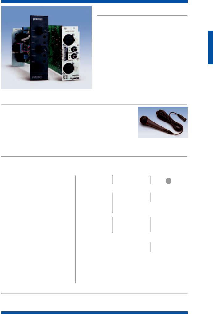
Power-supply modules
The power-supply module takes care of supplying the power needed to operate all the components of the system (with the exception of the power amplifiers). It has electronic protection against short-circuits and overloads. On the front panel, in addition to the main ON/OFF switch, there are also three signalling lamps indicating the power-supply sources (AC/DC) and the power supply status (ON/OFF). A connector is provided for adding further PMS2002-B (up to a maximum of 3) card-cages to expand the connection, by means of the CV36 cable. The PM2011-V module is the version for use in VES systems according to IEC 60849 standards and has a microcontroller that checks all the power supplies, both mains and battery.
P M 2 0 1 1 - B • P M 2 0 1 1 - V
S Y S T E M S
M O D E L
Mains power supply
External DC power supply
Stabilised power supply
Filtered power supply
MAX DC current consumption
Consumption
Width of module, mm
Weight, kg
T E C H N I C A L S P E C I F I C A T I O N S
PM2011
230 V ±10% 50/60 Hz
24 V ±10%
±15 V/200 mA max
+24 V/1 A max
1.4 A
40 VA (max)
58
0.940
1.4
P M 2 0 2 0 - B ( - V )
P M 2 0 2 3 - B
P M 2 0 2 0 - V
P M 2 0 2 0 - B
Dual input module
The PM2020-B module has two inputs to which audio sources of various types can be connected. The module can be set to take both microphone signals and high-level signals. Each channel has a disconnectable phantom power supply, a direct pre-amplified output, two-band tone control, an input for enabling of internal priority / chime / gate and a circuit for activating the external control channel. The output level and tone controls are on the front panel. The level of priority in respect of other input modules depends on the position of the module within the card-cage. Each of the two inputs can be equipped with a transformer with galvanic separation (TM80 or TM92) and an effective dynamics-limiting circuit (AC33), which considerably improves playing out of voice messages if there are strong variations in the level of the sound coming from the microphone.
Dual-input module for M961-V emergency microphone
The PM2020-V module is similar to the PM2020-B module, with the only difference that |
|
|
|
|
||||||
|
|
|
|
|||||||
input no. 1 is a dedicated input for connecting an M961-V emergency microphone in the |
|
|
|
|
||||||
|
|
|
|
|||||||
|
|
|
|
|||||||
VOX mode with top priority over any signal. |
|
|
|
|
|
|
|
|
|
|
|
|
|
|
|
|
|
|
|
||
The M961-V emergency microphone is controlled in accordance with IEC 60849 stan- |
|
|
|
|
||||||
|
|
|
|
|||||||
dards, and is an element of the critical path that is monitored continuously by the system’s |
|
|
|
|
||||||
|
|
|
|
|||||||
CPU (PM2021-V). This microphone should be installed, preferably, inside a special |
|
|
|
|
||||||
|
|
|
|
|||||||
soundproofed container in order to avoid generation of “improper” calls or false alarms. |
M 9 6 1 - V |
|
|
|||||||
P M 2 0 2 3 - B |
|
|
|
|
|
|
|
|
|
|
|
|
|
|
|
|
|
|
|
||
Dual input module with VOX function |
|
|
|
|
|
|
|
|
|
|
This module differs from the PM2020-B due to the VOX functioning mode of the two inputs. |
|
|
|
|
||||||
|
|
|
||||||||
|
|
T E C H N I C A L S P E C I F I C A T I O N S |
||||||||
|
|
|
|
|
|
|
|
|
|
|
|
|
|
|
|
|
|
|
|||
M O D E L |
|
PM2020 |
-B |
|
PM2023 |
-B |
|
PM2020 |
-V |
|
|
|
|
|
|
|
|
|
|
(Input “2”) |
|
|
|
|
|
|
|
|
|
|
||
No. and type of inputs |
|
|
|
2 electronically balanced |
|
|
||||
Input sensitivity setting |
HIGH |
MEDIUM |
|
|
LOW |
|||||
|
|
|
|
|
|
|
|
|
|
|
Sensitivity |
1.7 mV |
285 mV |
|
|
700 mV |
|||||
Impedance |
1 kΩ |
|
|
|
200 kΩ |
|
|
|||
Frequency response (0÷ -3 dB) |
100÷20,000 Hz |
|
|
40÷28,000 Hz |
||||||
Distortion |
|
|
|
<0,1% |
|
|
|
|
||
|
|
|
|
|
|
|
|
|
|
|
Signal/noise ratio (“A”-weighted) |
67 dBA |
85 dBA |
|
|
90 dBA |
|||||
Max. input signal |
50 mV (THD<1%) |
- |
|
|
|
- |
|
|||
|
|
|
|
|
|
|
|
|
|
|
Max. input signal with limiter |
500 mV (THD<1%) |
- |
|
|
|
- |
|
|||
Separation between inputs (at 10 kHz) |
|
|
|
>70 dB |
|
|
|
|
||
|
|
|
|
|
|
|
|
|
|
|
Tone correction |
|
|
|
±10 dB (100 Hz/10 kHz) |
|
|
||||
Output level before level control |
|
|
|
290 mV |
|
|
0.7 V (0 dB) |
|||
|
|
|
|
|
|
|
|
|
|
|
Output level after level control |
|
|
|
0÷1 V |
|
|
0÷0.7 V (0 dB) |
|||
Output impedance |
|
|
|
1 kΩ |
|
|
|
|
||
|
|
|
|
|
|
|
|
|
|
|
Precedence attenuation |
|
|
|
|
|
|
>50 dB |
|
|
|
PHANTOM supply |
|
|
|
15/24 V |
|
|
|
|
||
|
|
|
|
|
|
|
|
|
|
|
Power consumption |
|
|
|
+15V/20 mA, -15 V/20 mA |
|
|
||||
Module width, mm |
|
|
|
38 |
|
|
|
|
|
|
|
|
|
|
|
|
|
|
|
|
|
Weight, kg |
|
|
|
0.270 |
|
|
|
|
||
|
|
|
|
|
|
|
|
|
|
|
Accessories for PM2020-B, PM2023-B and PM2020-V
AC33 Dynamics limiter (single channel)
TM80 Input repeating coil with Mumetal shielding for low-level signals
TM92 Input repeating coil with Mumetal shielding for high-level signals
S Y S T E M S
1.5
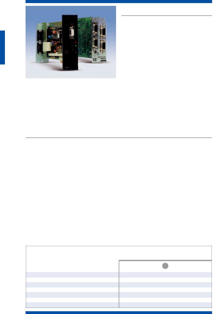
Module CPU P M 2 0 2 1 - B
+ S W P M B 1 . 0 Programming Software
The PM2021-B module contains the CPU for managing a system for sound-broadcasting alone, together with the SWPMB1.0 software. The module administers and co-ordi- nates the activities of the PMB131 and PMB136 digital consoles connected to the two RS485 serial outputs, and is able to dialogue with a PC through a separate RS232 line.
Through a local serial line, it distributes the commands to the PM2042-B relay cards and to the PM2060-B tuner, if any. It is possible to connect up to 31+31 consoles to the two output lines.
P M 2 0 2 1 - B ( - V ) |
The software SWPMB1.0 enables the following parameters to |
|
be programmed in the non-volatile memory: |
||
|
•Microphone signal level
•Activation/de-activation of the Intercom function and output level of the monitoring loudspeaker (PMB136 only)
•Activation of the “treble boost” for stressing the treble frequencies
•Activation of the “low cut” filter if there are any horn-type loudspeaker units in the system
•Reading of the priority level of the call stations set locally
•Selection of the radio station (PMB136 only)
•Volume control of the radio station that is on the air
•Stations in a call status displayed with the selected zones.
Module CPU P M 2 0 2 1 - V
+ S W P M S 1 . 0 Programming software
The PM2021-V module contains the CPU for controlling a sound-broadcasting and evacuation system together with the SWPMS1.0. software The module administers and co-ordinates the activities of the PMB131 and PMB136 digital consoles and is able to manage the dialogue with the PC through a separate RS232 line. The commands sent to the PM2011-V, PM2020-V, PM2042-V, PM2045-V, PM2061-V, PM29093-V cards and to the PM2060-B tuner, if any, lead out from this module. The software takes care of managing addressing of the evacuation and alert signals, of the emergency microphone and of programming of the input and output contacts associated with alarm signals or messages. Up to 87 amplifiers (with PM2092-V cards) can be connected to the two RS485 serial outputs, while two more outputs are dedicated outputs for connecting up to a maximum of 31 call stations per system. A permanent or temporary link to a PC, through the RS232 serial line, will enable programming and the system status to be viewed, as well as the alarm logging. The alarms are stored in a non-volatile memory (up to 100 events with their dates and times). Up to 16 different configurations are possible. They can be called up by means of a single control. Permanent use of a PC is recommended in integrated safety systems for displaying the following:
•System configuration
•The number and status of the modules/amplifiers installed in the system
•The parameters referred to the loudspeaker lines
•The status reports of the broadcasting section: present zones - activated zones - enabled console
•Report of failure status: line impedance, amplifier status, end-of-line (EOL) control, critical path
•Fault logging (last 99 with date/hours/minutes), resettable with a password
•Remote-metering of the consoles
•Remote-metering of the amplifiers.
S Y S T E M S
M O D E L
Frequency response (+3 dB)
Distortion
S/N ratio
Tape recorder output (unbalanced)
Power consumption
Width of module, mm
Weight, kg
T E C H N I C A L S P E C I F I C A T I O N S
PM2021
100 Hz ÷ 20 kHz
<0.2%
80 dB
1.7 V
+24 V/300 mA, +15 V/20 mA, -15 V/20 mA
38
0.300
1.6
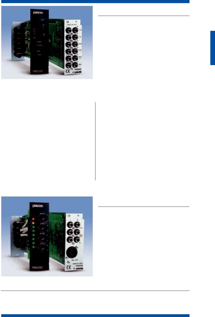
P M 2 0 2 2 - B
AUX input module
This module enables both stereo and mono high-level music sources to be connected to the system.
The input switch can select up to five signal sources. The Tuner input is equipped with individual sensitivity adjustment.
P M 2 0 2 2 - B
|
|
T E C H N I C A L S P E C I F I C A T I O N S |
|
|
|
||
M O D E L |
|
|
|
|
PM202 |
2-B |
|
|
|
|
|
Selectable inputs |
5 |
|
|
Sensitivity/tuner input impedance |
200 mV÷4 V/20 kΩ |
||
|
|
|
|
Sensitivity/Aux1 input impedance |
200 mV/47 kΩ |
||
Sensitivity/Aux2 input impedance |
950 mV/47 kΩ |
||
|
|
|
|
Sensitivity/CD input impedance |
450 mV/22 kΩ |
||
Sensitivity/tape-recorder input impedance |
200 mV/47 kΩ |
||
|
|
|
|
S/N ratio |
88 dBA |
||
Output level/impedance |
650 mV/1 kΩ |
||
|
|
|
|
Offset between channels (10 kHz) |
>60 dB |
||
Crosstalk between inputs (10 kHz) |
>70 dB |
||
|
|
|
|
Attenuation due to precedence |
>70 dB |
||
Power consumption |
+15 V : 10 mA/-15 V : 10 mA |
||
|
|
|
|
Width of module, mm |
38 |
|
|
|
|
|
|
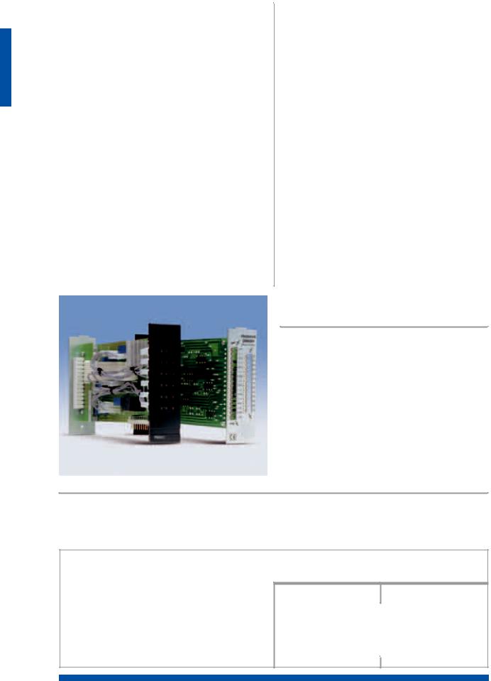
P M 2 0 4 0 - B
FUNCTIONAL FEATURES
•Electronically balanced main output that can be assigned to one of the three mixing buses
•Possibility of including an optional output repeater coil
•Two-tone/three-tone (chime) warning signal
P M 2 0 4 0 - B
Output module
This includes the audio signal mixing and control circuits (level and tone) present on the various different buses: PA channel (mono bus), channel A & B (left and right channels). Among other things, it has an integrated warning signal generator, a LED-type level indicator and three-band tone control. The bus PA mixing output (mono) is electronically balanced, and it is also possible to use a repeater coil for providing galvanic isolation of the line. Each PM2040-B module can share the signals present on the mixing buses with any other output modules installed (thus obtaining several identical output lines but with separate level and tone controls), or it can isolate the buses in order to put together several independent systems inside a single card-cage.
•LED Vu-METER
•Three-band tone control
•Relay for delayed activation of the output: “anti-bump”
•Supplementary high-level input.
S Y S T E M S
1.7
S Y S T E M S
|
|
|
|
|
|
|
|
|
|
T E C H N I C A L S P E C I F I C A T I O N S |
|
|
|
||
M O D E L |
|
|
|
|
P M 2 0 4 |
0 - B |
|
|
|
|
|
|
|
PA OUTPUT |
|
Type |
electronically balanced |
||
|
|
|
|
Level/impedance |
775 mV/600 Ω |
||
Frequency response |
40÷20,000 Hz (0÷ -1 dB) 25÷100,000 Hz (0÷ -3 dB) |
||
|
|
|
|
Distortion |
<0.1% |
||
|
|
BUS A & B output (stereo) |
|
|
|
|
|
Type |
unbalanced |
||
Level/impedance |
770 mV/1 kΩ |
||
|
|
|
|
Frequency response |
40÷20,000 Hz (0÷ -1 dB) 25÷100,000 Hz (0÷ -3 dB) |
||
Distortion |
<0.1% |
||
|
|
|
|
|
|
TAPE output |
|
Type |
unbalanced |
||
|
|
|
|
Level/impedance |
450 mV/1 kΩ |
||
Frequency response |
40÷20,000 Hz (0÷ -1 dB) 25÷100,000 Hz (0÷ -3 dB) |
||
|
|
|
|
Distortion |
<0.1% |
||
|
|
General |
|
|
|
|
|
Sensitivity/Auxiliary input impedance |
290 mV/50 kΩ |
||
S/N ratio of auxiliary input (“A”-weighted) |
> 94 dBA |
||
|
|
|
|
Bass/treble tones correction |
± 10 dB (100 Hz)/(10 kHz) |
||
Middle tones correction |
± 6 dB (1 kHz) |
||
|
|
|
|
Insertion delay |
2 seconds |
||
Power consumption |
24 V/17 mA, +15 V/22 mA, -15 V/18 mA |
||
Width of module, mm |
38 |
|
|
Weight, kg |
0.270 |
||
P M 2 0 4 1 - B • P M 2 0 4 3 - B
FUNCTIONAL FEATURES
•Override control for each zone
•6 dual-exchange relays
•Socket for connecting one or more microphone bases (B500 range)
P M 2 0 4 1 - B • P M 2 0 4 3 - B Zone selection module
(for B500/xx analogue call stations)
This module enables one or two amplification lines (generally speaking one music line and one announcement line) to be sent to more than one listening zone (up to 6). Microphone stations B500/12, /24 and /32 can be used to select the zones. The zones are selected by means of dualexchange relays, one of which is used for the “override” function (cancellation of the local attenuation levels of the loudspeakers). When using a double amplification channel (speech and music), it is possible to broadcast announcements to certain zones without breaking off the music being broadcast to the zones not affected by the call. As compared with the PM2041-B module, the PM2043-B module also has 6 switches mounted on the front panel for directing background music to the zones.
•Pull-out bayonet terminal strips
•Call/music selection for each zone
•Broadcasting of music can be disabled for or sent to each single zone.
T E C H N I C A L S P E C I F I C A T I O N S
M O D E L |
|
PM2041 |
-B |
PM2043 |
-B |
|
|
|
|
|
|
Numbers of relays |
|
6 dual-exchange relays |
|||
Power switchablee by each relay |
|
|
100 W |
||
|
|
|
|
|
|
Power consumption |
|
|
24 V/80 mA |
||
Width of module, mm |
|
|
38 |
|
|
|
|
|
|
|
|
Weight, kg |
0.270 |
0.320 |
|||
|
|
|
|
|
|
1.8
P M 2 0 4 2 - B • P M 2 0 4 4 - B Digital zone selection modules
(for PMB131 and PMB136 digital bases)
This module enables one or more amplification lines (gen-
erally speaking one music line and one announcement line)
to be sent to several listening zones (up to 6). It is necessary
to use the PMB131 or PMB136 digital microphone stations
to select the zones. The zones are selected by means of
dual-exchange relays, one of which is used for the “over-
ride” function (cancellation of the local attenuation levels of
the loudspeakers). When using a double amplification
channel (speech and music), it is possible to broadcast
announcements to certain zones without breaking off the
 music being broadcast to the zones not affected by the call. A maximum load of 500 W can be connected to each zone. The great versatility of this card enables various different kinds of connection, with either single or double amplification lines. It is possible to connect up to a maximum of 4 amplifiers to the module (two for the music line and two for the announcement line). As compared with the PM2042-B module, the PM2044-B module also has 6 switches mounted on the front panel for sending background music to the zones.
FUNCTIONAL FEATURES
• 6 dual-exchange relays |
• 24 VDC output for activating All Call by means of an out- |
• Pull-out bayonet terminal strips |
side switch |
• Override control |
• 6 cards for a maximum of 36 zones can be installed in the |
• Call/music selection for each zone |
system |
|
|
T E C H N I C A L S P E C I F I C A T I O N S |
||||
|
|
|
|
|
||
M O D E L |
|
|
|
|
|
|
|
|
PM2042 |
-B |
PM2044 |
-B |
|
|
|
|
|
|
|
|
Power switchable by each relay |
|
|
|
500 W |
||
Maximum current switchable by each relay |
|
|
|
5 A |
||
|
|
|
|
|
|
|
24 VDC power consumption |
|
|
|
100 mA |
||
Width of module, mm |
|
|
|
38 |
|
|
|
|
|
|
|
|
|
Weight, kg |
0.310 |
0.370 |
||||
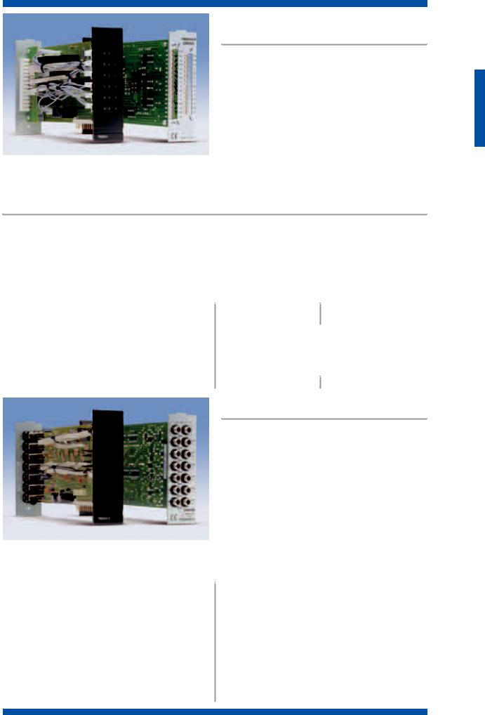
P M 2 0 4 5 - V
Signal routing module
The module manages routing of the emergency signals, under the control of the PM2021-V CPU, to the amplifiers.
The module has program 6 inputs and 6 outputs for 6 amplifiers. During normal operation (not in an emergency), the signals applied to the inputs are reproduced exactly on the outputs. In emergency conditions, the VES signals present on the system BUS are taken by it and routed to the outputs on the basis of the program written into the CPU. The module also has an input for an external source, that can be connected as required to any of the system’s four emergency lines.
P M 2 0 4 5 - V
|
T E C H N I C A L S P E C I F I C A T I O N S |
||
M O D E L |
|
|
|
|
|
|
|
|
PM2045 |
-V |
|
|
|
|
|
Input/output gain |
|
0 dB |
|
Input impedance |
|
100 kΩ |
|
|
|
|
|
Output inpedance |
|
330 Ω |
|
Distortion (@ 1 kHz) |
<0.1% |
||
|
|
|
|
S/N ratio |
|
>90 dB |
|
Frequency response |
|
40÷20,000 Hz |
|
|
|
|
|
Width of module, mm |
38 |
|
|
Weight, kg |
0.290 |
||
|
|
|
|
S Y S T E M S
1.9
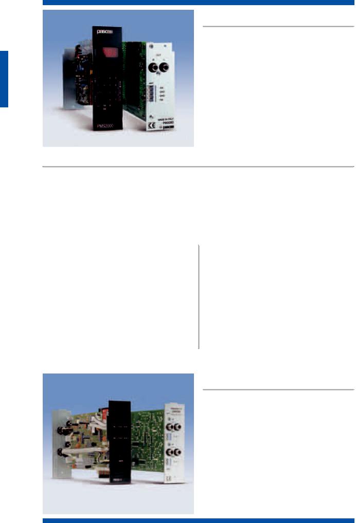
P M 2 0 6 0 - B
AM/FM tuner module
The PM2060-B module is a highly sophisticated and compact digital receiver with frequency-synthesis tuning which has a decoder for stereo broadcasting stations. A four-digit digital display shows the frequency of the station to which the system is tuned, while all the control functions of the receiver are accessible via a dedicated keypad on the front panel.
The tuner audio signal is sent to the mono mixing bus (“PA” channel) and to the stereo output, which is separate from the volume control and accessible from the rear of the module.
P M 2 0 6 0 - B
FUNCTIONAL FEATURES |
|
• 2 receiving bands (AM/FM) with automatic station |
• Digital volume and tuning control |
searching |
• Stereo output separate from volume control |
• Automatic storage of the ten best AM and/or FM broad- |
• Output on the PA bus |
casting stations (BSM) |
• 10 AM and 10 FM stations storable |
• Direct selection of the receiving frequency |
• Automatic storage of the volume level |
|
|
T E C H N I C A L S P E C I F I C A T I O N S |
|
|
|
||
M O D E L |
|
|
|
|
PM2060 |
-B |
|
|
|
|
|
Tuning range |
FM 87.5 MHz÷108.05 MHz |
||
AM (Europe) tuning range |
522 kHz÷1629 kHz |
||
|
|
|
|
AM (USA) tuning range |
520 kHz÷1610 kHz |
||
Sensitivity |
FM: 10 µV - AM: 30 µV |
||
|
|
|
|
Frequency response |
40÷15,000 Hz (0÷ -3 dB) |
||
Signal/noise ratio |
FM: 70 dB - AM: 50 dB |
||
|
|
|
|
Number of stations that can be stored |
10 (FM)+10 (AM) |
||
Power consumption |
24 V/140 mA, +15 V/4 mA, -15 V/6 mA |
||
|
|
|
|
Width of module, mm |
38 |
|
|
Weight, kg |
0.320 |
||
S Y S T E M S
P M 2 0 6 1 - V
Digital message generator module
The PM2061-V module is a controlled pre-recorded message
generator, for evacuation systems according to IEC 60849
standards. It enables two messages to be played out simulta-
neously (i.e. one EVACUATION message and one ALERT mes-
sage. It is possible to manage the recorder directly via the key-
pad or through the CPU 2021-V. The messages can either be
played out automatically (for example, by connecting the sys-
tem to a fire-fighting control unit) or manually via external
contacts. Recording of the messages, which is possible by
means of any dynamic microphone, does not require any
adjustments, thanks to a sophisticated automatic gain control
system which is able to offset even considerable variations in
the voice level. The messages are stored digitally in the Multi-
mediacard®, which enables a recording time of 4 minutes per
message.
P M 2 0 6 1 - V
1.10

|
|
FUNCTIONAL FEATURES |
|
• Perfect intelligibility of the messages being played out |
• Protected access to keypad functions |
• Ease of use |
• Activation of fire-fighting control unit, from PMB130-V |
• Pause command for recording sequential multi-language |
control and from outside contact. |
messages |
|
|
|
T E C H N I C A L S P E C I F I C A T I O N S |
||
|
|
|
||
M O D E L |
|
|
|
|
|
|
PM2061 |
-V |
|
|
|
|
|
|
Lenght of recording per channel |
|
4 minutes |
||
S/N ratio |
|
56 dB |
||
|
|
|
|
|
Frequency response (-3 dB) |
|
300÷6,000 Hz |
||
Distortion (@ 1 kHz) |
<1.3% |
|||
|
|
|
|
|
24 VDC power consumption |
|
24 VDC/45 mA, +15 VDC/38 mA, -15 VDC/26 mA |
||
Width of module, mm |
38 |
|
||
|
|
|
|
|
Weight, kg |
0.300 |
|||
|
|
|
|
|
P M 2 0 9 1 - B
Bus expansion module
The expansion module allows to expand the system up to a maximum of three card cages. The connection among the cages carries the signals of the three mixing buses (PA, L and R channels), the serial control line, the priority line and chime.
P M 2 0 9 2 - V
Card for serial control of power amplifiers
The PM2092 card enables simple and rapid testing of the PMWxx power amplifiers.
It can be used in any system, even for sound-broadcasting only, to carry out the following functions:
•Measuring the impedance of the loudspeaker line
•Diagnosis of correct operation of the amplifier (gain, power supply, electronic protection and operating temperature)
•Checking insulation to earth (GND FAULT)
•Volume control of the amplifier by means of a remote potentiometer (max. 1 km)
•Add a second input that works either as selected or mixed (automatic attenuation of the secondary input) one
•Control of power relay
•Operation in “LOW POWER” energy-saving mode
•Possibility of switching a failed amplifier automatically to the stand-by unit by means of the PM2095 circuit.
In VES systems, it is essential to add the PM2092 card to the power amplifiers. In this case, the card will be controlled by means of a serial interface and it will therefore be possible to view all the control parameters and to change them via a PC. These parameters include:
-Reading of the reference impedance for the test
-Maximum and minimum values between which the test is valid
-Reading of test status
-Testing for the presence of the input signal
-Measurement of temperature of the power transistors
-Volume control
-Remote control of the relay.
It is also possible to monitor continuity of the loudspeakers lines using PM2094-V cards at the end of the line.
P M 2 0 9 5
Card for activating stand-by amplifiers
The card, which has to be installed on a DIN guide or using the special AC2095 accessory, receives from the PM2092-V module the command to activate one stand-by amplifier for each group of 4 amplifiers being monitored. The card can be connected to others in cascade formation by means of quick-fitting connectors so as to create other configurations: 1 out of 4, 1 out of 8, 2 out of 8 etc., in multiples of 4. This card has to be powered by a 24 VDC external power supply.
P M 2 0 9 4 - V
End of-line control card
The loudspeakers lines from PMW amplifiers with PM2092-V control cards can be kept under control using PM2094-V end- of-line cards.
The digital monitor identifies the exact point of the failure and its type (break or short circuit), even if the line is split up into several branches (up to 3), which makes laying the lines far simpler and less expensive.
S Y S T E M S
1.11
|
|
|
|
|
|
|
|
|
|
|
P M 2 0 9 3 - V • P M 2 0 9 3 - V L |
|
|
|
|
|
|
|
|
|
|
|
I/O modules |
|
|
|
|
|
|
|
|
|
|
|
The PM2093-V module has 8 input contacts and 8 output |
|
|
|
|
|
|
|
|
|
|
|
|
|
|
|
|
|
|
|
|
|
|
|
|
|
|
|
|
|
contacts, the functions of which can be configured via |
|
|
|
|
|
|
|
|
|
|
|
software. |
|
|
|
|
|
Thanks to the control inputs, any signalling resulting from |
|
|
|
|
|
|
|
|
|
|
|
|
|
|
|
|
|
the closing of external contacts (e.g. the contacts of a fire- |
|
|
|
|
|
|
|
|
|
|
|
fighting system control unit) can be read. The output con- |
|
|
|
|
|
|
|
|
|
|
|
tacts can be used to operate external signalling devices |
|
|
|
|
|
|
|
|
|
|
|
(relays, lamps, etc.); there is a remote control connector |
|
|
|
|
|
|
|
|
|
|
|
enabling remote connections to be made (up to a distance |
|
|
|
|
|
|
|
|
|
|
|
of 1 km) to the external devices. The PM2093-VL model is |
|
|
|
|
|
|
|
|
|
|
|
equipped with 8 LEDs on the front panel, connected to the |
|
|
|
|
|
|
|
|
|
|
|
output contacts, providing lights for signalling the following |
|
|
|
|
|
|
|
|
|
P M 2 0 9 3 - V • P M 2 0 9 3 - V L |
possible failure situations: |
|
|
|
|
|
|
|
|
|
Output contact and LED activated |
Type of failure: |
||
|
|
1. |
Mains |
Mains power lack (primary power supply) |
|
|
|
2. |
Battery |
Failure of secondary power supply |
|
|
|
3. |
Fire link |
Failure of connection to the fire-fighting system control unit |
|
|
|
4. |
Critical Path |
Failure detected on the critical path by the control signal |
|
|
|
5. |
Messages |
Failure of the message generator (even only of a single channel) |
|
|
|
6. |
CPU |
Failure of the CPU |
|
|
|
7. |
Amp |
Failure of a system amplifier (including stand-by units) |
|
|
|
8. |
Spk Line |
Failure on the loudspeaker line (change in impedance). |
|
Accessories
•AC36 Clock card for fault logging.
•AC37 RS485 serial card for remote control.
•AC38 Alarm-tone card: 19 different types of alarm are available, covering a full variety of requirements.
•AC39 Card for connecting the PMB130-V control console.
|
|
T E C H N I C A L S P E C I F I C A T I O N S |
|
|
|
||
M O D E L |
|
|
|
|
PM2093-V |
PM2093-VL |
|
|
|
|
|
Power consumption |
24 V/75 mA |
||
Maximum voltage applicable to the output relay contacts |
30 V |
||
|
|
|
|
Maximum permissible current on the contacts of the relays |
0.5 A |
||
Maximum consumption |
24 V/100 mA |
||
|
|
|
|
Activated input |
10 ÷ 28 Vcc |
||
Not activated input |
-1 ÷ +1 Vcc |
||
|
|
|
|
Width of module, mm |
38 |
|
|
Weight, kg |
0.270 |
||
|
|
|
|
S Y S T E M S
1.12

P M B 1 3 1
P M B 1 3 6
Programmable call stations
Up to a maximum number of 31 units can be connected to the PMS2000 audio system through the RS485 serial line. The units are connected to one another in cascade formation, and the connecting cables carry both the analogue audio signal and the digital signal for the controls and station addresses. They can only be used with modules PM2021-B and PM2042-B.
P M B 1 3 6
P M B 1 3 1
P M B 1 3 1
The PMB131 call station is equipped with a push button (for short announcements) and a locking key for selecting a
zone or a group of zones. Each call station can be programmed to operate within a specific zone or group of zones, up to a maximum of 36 (All Call).
Programming is carried out by means of a PC connected temporarily to the PM2021 module.
P M B 1 3 6
The PMB136 call station can make selective calls to up to a maximum number of 36 zones and has 3 function keys, to which one or more zones can be assigned by means of a programming procedure carried out directly from the call station in question. The keypad can also be used to set the various different parameters such as: call station address, priority level (up to 7), microphone sensitivity setting, tone control, volume control, selection of the tuner programme and enabling of the Intercom function.
The unit has 36 LEDs for signalling the zones that have been selected or seized and a loudspeaker for the intercom function. This enables the various different operators to communicate with each other and to listen to the announcements that are being broadcast. All the parameters of the unit can be programmed by means of a PC to be connected to the PM2021 module as well as directly via the keypad. The PC can also be used as a diagnostic unit to check whether all the call stations that are connected dialogue correctly with the PMS2000.
FUNCTIONAL FEATURES
•Max. overall length of the connecting line: 1 km
•24 VDC local power supply socket.
|
|
|
T E C H N I C A L S P E C I F I C A T I O N S |
|
|
|
|
|
|
M O D |
E L |
|
PMB131 |
PMB136 |
|
|
|
|
|
Max. consumption |
|
44 mA |
||
Power-supply voltage |
|
24 VDC |
||
|
|
|
|
|
Output level |
|
|
|
1 V |
Max. sound pressure |
|
130 dB |
||
|
|
|
|
|
Size of (LxHxW) mm |
142x80x205 |
300x80x205 |
||
Weight, kg |
|
|
0.700 |
1.560 |
Accessories |
|
|
|
|
MB30-GLN |
Electret microphone on flexible stem, total length 430 m |
|
||
MB60-GLN |
Electret microphone on flexible stem, total length 680 m |
|
||
AC34 |
Line termination (pack of 2 pcs.) |
|
|
|
AC501 |
Brackets for flush-mounting |
|
|
|
AC32 |
Microphone transformer module |
|
|
|
CV301-B |
Connecting cable, length 1.5 m |
|
|
|
CV305-B |
Connecting cable, length 5 m |
|
|
|
CV310-B |
Connecting cable, length 10 m |
|
|
|
CV320-B |
Connecting cable, length 20 m |
|
|
|
31/135 |
Multi-lead extension cable |
|
|
|
AC304 |
9-pole extension connector kit. |
|
|
|
S Y S T E M S
1.13
S Y S T E M S
P M B 1 3 0 - V
VES console
P M B 1 3 9 - V
Extension module
The PMB130-V digital console, which
has a microphone controlled by a large
LCD, can be used to perform many
functions making the system easier to
control and operate.
The PMB139-V extension module
enables 12 programmable short-cut
keys for one or more functions to be
 added. It is possible to connect up to P M B 1 3 0 - V P M B 1 3 9 - V three expansion modules to the
PMB130-V.
The console can be used for the following:
•To display the fault logging and of the alarms with the relevant date/hour/minutes
•To make service calls to the single or to groups of zones
•To check the status of the whole system. Any failures will be signalled by means of LEDs
•To send Evacuation and/or Alert signals to the single zones via the microphone
•To send automatically Evacuation and Alert messages generated by the fire-fighting control unit.
A safety key supplied with the unit enables authorised personnel to:
•Reset an alarm condition, this event being recorded in the memory with the date/hour/minutes
•Send out manually pre-recorded evacuation and alarm messages to zones involved in alarms, this event being recorded in the memory with the date/hour/minutes
•Send out live Evacuation and Alert messages.
A built-in buzzer also provides acoustic signalling of a failure status. The buzzer can be reset by means of the safety key.
|
|
P M W 6 0 |
|
|
P M W 1 2 0 |
|
|
|
|
|
P M W 2 4 0 |
|
|
Modular amplifiers |
|
|
|
|
|
Careful design and a choice of reliable |
|
|
|
|
|
|
|
|
high-tech components led to the cre- |
|
|
|
|
|
ation of this range of extremely com- |
|
|
|
|
|
pact amplifiers, capable of functioning |
|
|
|
|
|
even in the toughest conditions. The |
|
|
|
|
|
forced-ventilation cooling system and |
|
|
|
|
|
the numerous electronic and thermal |
|
|
|
|
|
protection devices ensure maximum |
|
|
|
|
|
reliability of operation in time. These |
|
|
|
|
|
amplifiers differ from one another only |
|
|
|
|
|
in their output power and their sizes |
|
|
|
|
|
(two 60 W or two 120 W amplifiers |
|
|
|
|
|
take up the same space as one 240 W |
|
|
|
|
|
amplifier). Each PMS2001 card-cage |
|
|
|
P M W 2 4 0 |
P M W 1 2 0 |
|
|
can contain two PMW240 or four |
|
P M W 6 0 |
||
PMW60/PMW120 amplifiers, plus all |
||
|
||
|
the intermediate configurations. |
The amplifiers of the PMWxxx range can also be used separately from the PMS2000 system whenever such a small layout and high reliability are required, since they can be housed in any suitable container or be placed on shelves. In evacuation systems, it is essential to use the PM2092-V serial control card, to be plugged into the amplifier. The LEDs on the front panels have the dual function of VU Meters (in normal conditions) or of indicating the type of failure, if any, detected by the PM2092-V control card.
FUNCTIONAL FEATURES |
|
• For running on 230 VAC or 24 VDC |
• Front-panel overload and thermal-protection signalling |
• Double input socket (for connecting more than one amplifi- |
• Pull-out bayonet output terminal strip |
er in parallel) |
• Galvanic signal balancing via optional TM92 internal trans- |
• PA/HF (filtered/full passband) operation |
former |
• Forced fan-cooling with electronic control and protection |
• Remote potentiometer connection via optional PM2092-V |
circuit |
control card |
1.14
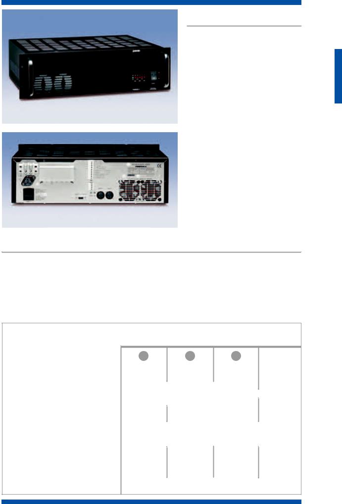
P M W 5 0 0 - V
P M W 5 0 0 - V
P M W 5 0 0 - V
C o n t r o l l e d 5 0 0 W a m p l i f i e r
The PMW500-V is a 500W amplifier in the PMW range which includes as standard the PM2092-V card for internal and speaker line control. The unit conforms to the IEC60849 rule for voice evacuation systems. Its comprehensive design and high tech solutions ensure reliability and operation. The high contruction and operational standards are met with the use of two temperature controlled forced ventilation fans, which cool the power transistors only when overheating occurs, thus preventing mechanical wearing and dust collection.
FUNCTIONAL FEATURES |
|
• 230Vac and 24Vdc power supply |
• Galvanic balancing of signal via optional TM92 internal |
• Double input (to parallel connect more units) |
transformer |
• PA/HF modes (filtered/full bandwidth) |
• Remote potentiometer connection via standard PM2092-V |
• Forced cooling with two electronic controlled fans |
control card |
• Front panel LED for in-use overheating protection warning |
• Control and diagnosis of main functions via PM2092-V con- |
• Pull-out bayonet output terminal strip |
trol card |
T E C H N I C A L S P E C I F I C A T I O N S
M O D E L |
PMW60 |
PMW120 |
|
PMW240 |
|
PMW500 |
-V |
|
|
|
|
|
|
|
|
|
|
Related output power with mains power supply |
60 W RMS |
120 W RMS |
240 W RMS |
500 W RMS |
||||
Related output power with DC power supply |
47 W RMS |
90 W RMS |
150 W RMS |
450W RMS |
||||
|
|
|
|
|
|
|
|
|
Power output |
|
100, 70, 50 V - 8Ω, 4Ω |
|
|
100, 70, 50 V - 16Ω |
|||
Distortion and rated output with mains power supply |
|
<1% |
|
|
|
|
||
|
|
|
|
|
|
|
|
|
Sensitivity/input impedance of main line |
|
770 mV/200 kΩ |
|
|
775 mV/100 kΩ |
|||
Signal/noise ratio (“A”-weighted) |
>83 dB |
|
|
>90 dB |
>80 dB |
|||
|
|
|
|
|
|
|
|
|
Frequency response at Pn (output 100V, -3 dB) |
40÷19000 Hz |
|
40÷20000 Hz |
50÷20000 Hz |
||||
Frequency response with highpass filter |
|
400÷12500 Hz (0 ÷ -3 dB) |
|
|
||||
|
|
|
|
|
|
|
|
|
Mains power supply |
|
230 V ±10%, |
50/60 Hz |
|
|
|||
External DC power supply |
|
|
22÷28 V |
|
|
|||
|
|
|
|
|
|
|
|
|
Consuption at the max. output (mains power supply) |
120 W/150 VA |
250 W/300 VA |
500 W/600 VA |
950 W/1150 VA |
||||
Current consuption at 24 VDC |
3,7 A (max) |
6,5 A (max) |
11 A (max) |
25 A (max) |
||||
|
|
|
|
|
|
|
|
|
Size (LxHxW) mm |
100x130x395 |
100x130x395 |
200x130x395 |
482x133x420 |
||||
Weight, kg |
5,2 |
6,5 |
|
|
10 |
|
25 |
|
|
|
|
|
|
|
|
|
|
Operating/storage temperature |
|
-10°C ÷ +45°C/-40°C ÷ +70°C |
|
|
||||
Safety |
|
according to CEI EN 60065 standards |
|
|
||||
S Y S T E M S
1.15
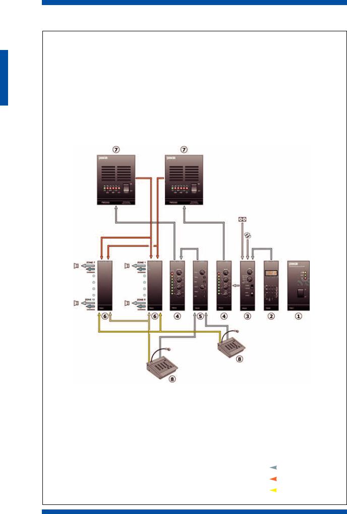
systems
S Y S T E M S
Examples of applications
System with simultaneous music and announcements. 12 zones, with 2 analogue microphone bases
Key |
|
|
|
|
1 |
PM2011-B |
power supply |
|
|
2 |
PM2060-B |
AM/FM tuner |
|
|
3 |
PM2022-B |
auxiliary inputs |
|
|
4 |
PM2040-B |
output |
|
SIGNAL |
5 |
PM2020-B |
double input |
|
|
|
|
|||
6 |
PM2041-B |
zone selection |
|
AMPLIFIER OUTPUT |
7 |
PMWxx |
amplifier |
|
|
|
|
|||
8 |
B500/12 |
microphone station |
|
RELAYS CONTROL |
|
||||
1.16
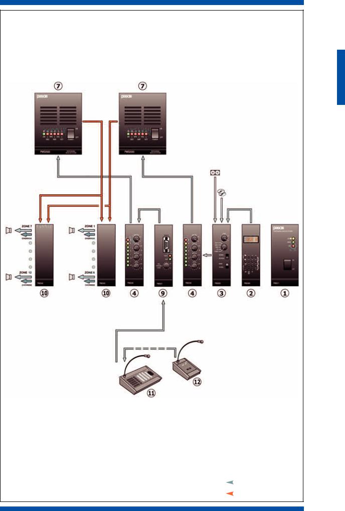
System with simultaneous music and announcements. 12 zones, with several digital microphone bases
Key |
|
|
1 |
PM2011-B |
power supply |
2 |
PM2060-B |
AM/FM tuner |
3 |
PM2022-B |
auxiliary input |
4 |
PM2040-B |
output |
7 |
PMWxx |
amplifier |
9 |
PM2021-B |
control |
10 PM2042-B selection of digital zones |
|
SIGNAL |
|
11 PMB136 |
microphone station |
|
|
|
|
||
12 PMB131 |
microphone station |
|
AMPLIFIER OUTPUT |
|
|||
S Y S T E M S
1.17
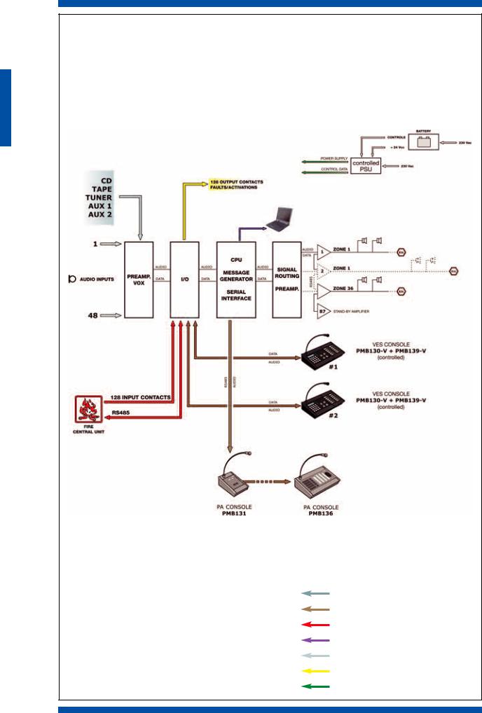
S Y S T E M S
Block diagram of the VES system.
SIGNAL
SIGNAL/DATA LINES
CONNECTION TO FIRE-FIGHTING UNIT
SERIAL DATA
LOUDSPEAKERS
CONTACTS
EMERGENCY POWER SUPPLY
1.18
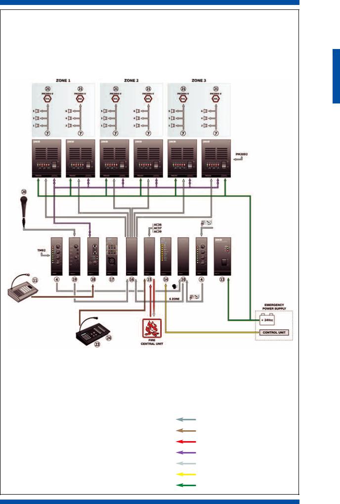
PA/VES system with background music and announcements. 3 zones, with interlaced loudspeakers network
Key |
|
|
4 |
PM2040-B |
output |
7 |
PMWxx |
amplifier |
10 PM2042-B |
selection of digital zones |
|
11 PMB136 |
microphone station |
|
13 PM2011-V |
controlled power supply |
|
14 PM2093-VL |
controlled I/O with LEDs |
|
15 PM2093-V |
controlled I/O |
|
16 PM2045-B |
matrix |
|
17 PM2061-V |
message generator |
|
18 PM2021-V |
CPU |
|
19 PM2020-V |
controlled dual imput |
|
20 M961-V |
emergency microphone |
|
21 PM2094-V |
end of line |
|
23 PMB130-V |
emergency and control console |
|
24 PMB139-V |
expansion for PMB 130-V |
|
ACCESSORIES
•AC36 system clock
•AC37 serial RS485
•AC39 PMB 130-V connection card
SIGNAL
SIGNAL/DATA LINES
CONNECTION TO FIRE-FIGHTING UNIT
SERIAL DATA
LOUDSPEAKERS
CONTACTS
EMERGENCY POWER SUPPLY
S Y S T E M S
1.19
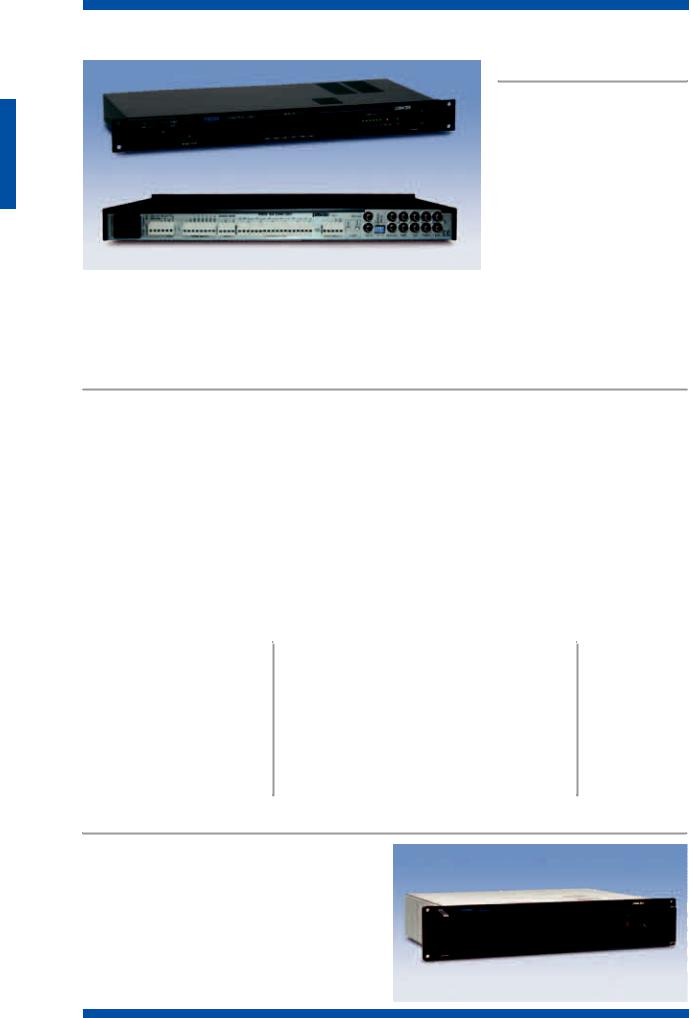
systems
P8036 • 6 zone voice/music switching unit
P 8 0 3 6
The panel enables a maximum of 6
zones to be selected by means of a
microphone base. The equipment can
be used both with the line signals
(before the amplifier) and with power
signals (output from the amplifier with
100 V line). The P8036 has provisions
for connecting two amplifiers (one for
music and one for speech) and it can
be configured to operate with a single
amplifier for both voice and music.
There are 4 inputs for auxiliary sound
 sources with selectors and level controls, one input on a terminal strip for connecting several stations of the B500 and B600 ranges and an input with VOX priority for sound sources, such as a message generator or an alarm-tone generator. The music source that was selected, adjusted in amplitude, will be available at the MUSIC OUT output , while the voice signal from the base or from the VOX input (depending on priority) will be available on the SPEECH OUT. If there is only one amplifier, this input will also provide the music featuring the lowest priority.
FUNCTIONAL FEATURES |
|
• Selection of voice/music on 6 zones by means of relays |
• Three-wire override connection |
• Possibility of activating/de-activating music for each zone |
• Optional warning signal (AC25) with volume and tone |
by means of front-panel switches |
control |
• 4 inputs for music sources with RCA type stereo connectors |
• Selection of priority of Base over VOX or VOX over Base |
• VOX line input on RCA type connector with automatic |
• Insulated contact controlled by microphone station for driv- |
precedence activation and All Call, suitable for connection |
ing an alarm message or tone |
with DAG9200 or DMG9016 |
• 6 line outputs for the 6 zones on screw-down terminal with |
• Input for amplified microphone bases of the B500 or B600 |
three-wire override connection |
range, with separate screw-down terminal strips for |
• MUSIC OUT and SPEECH OUT output |
audio/power/ precedence and for zone selection |
• Equipment for rack-mounting in 19” rack, height: 1 module |
• Separate 100 V inputs for music and for speech on screw- |
• Power supply: 230 VAC/24 VDC. |
down terminal |
|
S Y S T E M S
P 8 0 3 6 |
T E C H N I C A L |
S P E C I F I C A T I O N S |
||
|
|
|
|
|
|
|
|
|
|
VOX INPUT: |
|
AUX-TAPE-TUNER INPUTS: |
|
|
Sensitivity/impedance |
300 mV/46 kΩ |
Sensitivity/impedance |
100 mV/33 kΩ |
|
|
|
|
|
|
S/N |
89 dB |
S/N |
|
>92 dB |
Frequency response |
30 Hz÷20 KHz |
Frequency response |
25 Hz÷20 KHz |
|
|
|
|
|
|
BASE INPUT: |
|
CD INPUTS: |
|
|
Sensitivity/impedance |
190 mV/10 kΩ |
Sensitivity/impedance |
480 mV/45 kΩ |
|
|
|
|
|
|
S/N |
88 dB |
S/N |
|
>92 dB |
Frequency response |
50 Hz÷20 KHz |
Frequency response |
25 Hz÷32 KHz |
|
|
|
|
|
|
MIX OUT: Level/impedance |
775 mV/600 Ω |
MUSIC OUT: Level/impedance |
775 mV/600 Ω |
|
|
|
|
|
|
P 8 0 3 0
Container for special applications, 2 modular units high, including:
• Front panel with handles, mains switch and ON/OFF signalling lamp
• Rear panel, with mains connector and fuse, supporting a  printed circuit that contains ten 6-pole blocks with fast-on
  type contacts (female printed-circuit connectors and corre-
  sponding male connectors supplied with them). The print-
  ed circuit has provisions for housing up to 10 additional
  connector blocks. P 8 0 3 0
• 12 VDC/2 A stabilised power supply.
1.20
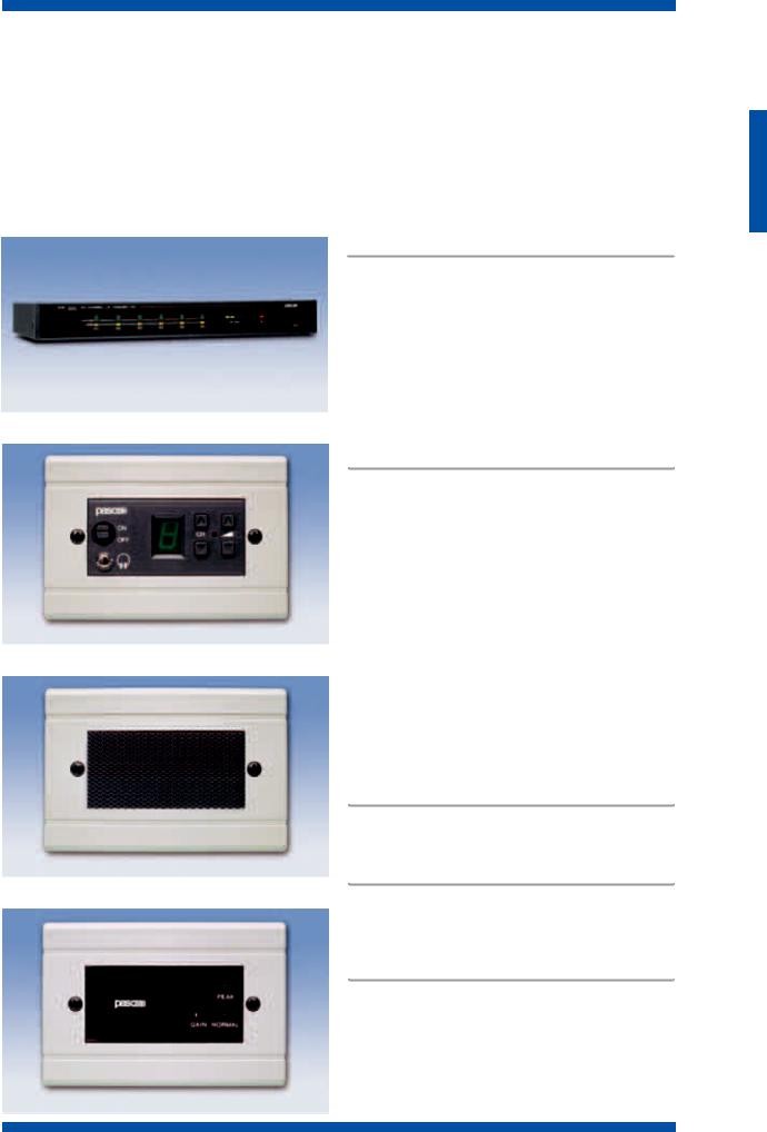
systems
SD200 • Multi-channel distribution system
The SD200 system enables simultaneous distribution of 6 different programmes over a single pair of wires. The ease of installation as compared with conventional systems makes it particularly suitable for sound-broadcasting to the single rooms of accommodation facilities such as hotels, nursing homes, tourist centres, residential centres, cruise ships, ferries and private homes. The heart of the system is the SDP220 receiver module, which can be installed in any room inside a normal flush-mounted box for wiring systems. The SDM200 modulator can provide a constant signal for a maximum of 80 SDP220 receivers. Continuous expansion, in multiples of 80 is possible, by including the SDB200 amplifier in the signal line. The SD200 system can also be used to manage up to 6 languages in fixed simultaneous translation systems. A cabled simultaneous translation system enables excellent listening quality, with no interference and a very high level of safety against unauthorised tapping.
S D M 2 0 0
S D P 2 2 0
S D M 2 0 0 Modulator
This system enables 6 signals from sources generated locally by CD or cassette players, tuners, etc. to be transmitted and mixed via a telephone pair. A pre-amplifier circuit adapts the amplitude of the signals of the sources for correct modulation of the respective carriers generated by a stage that functions according to the PLL technique, with quartzcontrolled reference frequency. The six modulated carriers are sent to an RF amplifier and then to the output sockets by means of an RF transformer that takes care of balancing and of the correct impedance value.
S D P 2 2 0 Receiver module
This module demodulates the signals distributed by the SDM200 modulator (or directly by cable radio systems). The receiver can be activated from a remote location, even if it is switched off, by means of a voltage of 12 VDC. This feature means that it is possible, if required, to force broadcasting of emergency messages to single listening zones. The module can be operated by means of a 12 VDC source or from the mains at 230 VAC by means of the SDT100 transformer contained in the SDA200-T loudspeaker module. The channels are selected cyclically by means of keys. The selected channel is shown on a display which has automatic brightness adjustment on the basis of the ambient light. Volume control is electronic. If the module is used in a conventional simultaneous translation system, it can be housed in the conference table or in the arm or backrests of the chairs. The messages can be listened to through headsets plugged into the sockets provided for them. For special installations, the modules can be supplied in customised versions with panels of various types.
S D A 2 0 0 Loudspeaker module
This module contains a 3 W - 8 Ohm loudspeaker. It can be connected to SDP220 receivers running on a 12 VDC power supply.
S D A 2 0 0 / S D A 2 0 0 - T |
S D A 2 0 0 - T |
|
In addition to the 3 W - 8 Ohm loudspeaker, this also contains |
|
a transformer, SDT100, from the mains 230 VAC voltage for |
|
the receiver module. |
S D B 2 0 0 Line amplifier
This must be used if the length of the line attenuates the signal excessively or, in any case, if the number of SDP220 receivers is greater than 80. Each SDB200 enables a further 80 receivers to be added. It is possible to expand the system to a practically unlimited number of receivers using the appropriate additional SDB200 amplifiers. For the 230 VAC mains power, it is necessary to add the SDT101 transformer.
S D B 2 0 0
S Y S T E M S
1.21
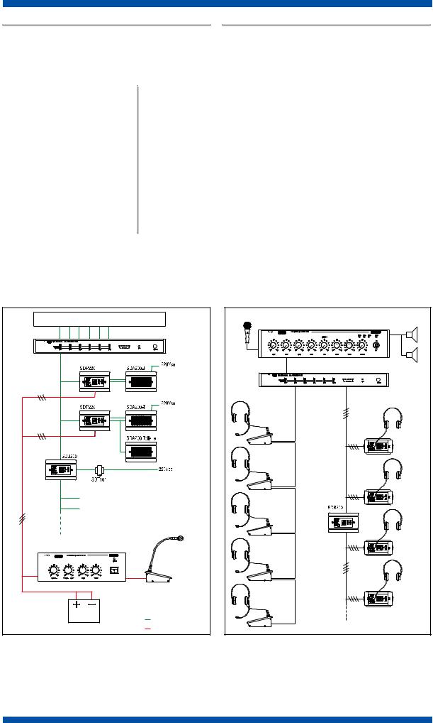
S D T 1 0 1
Transformer for 230 VAC mains power supply for the SDB200.
2 7 / 9 0 1
Box for flush-mounting the SDP220, SDA200(T) and SDB200 modules.
|
|
T E C H N I C A L |
S P E C I F I C A T I O N S |
S D M 2 0 0 |
|
||||
|
|
|
|
|
|
|
Generator |
6 frequencies, PLL type controlled by quartz oscillator |
|
|
|
|
|
|
|
|
Frequencies broadcast |
CH1=178 kHz; CH2=211 kHz; CH3=244 kHz; CH4=277 kHz; CH5=310 kHz; CH6=343 kHz; |
|
|
|
|
|
|
|
|
Output power |
carrier only - 10 mW / Channel; with modulation - 50 mW Peak / Channel (80% mod.) |
|
|
|
Output voltage attenuation |
about 0-26 dB |
|
|
|
|
|
|
|
|
Output line impedence |
25 Ω or 100 Ω |
|
|
|
|||
|
|
LF section |
channel modulators with automatic level control, lowpass filter and pre-enphasis to 3 dB at 6 kHz |
|
|
|
|
|
|
|
|
LF input impedence |
150 kΩ |
|
|
|
Sensitivity for 30% modulation |
150÷3000 mV |
|
|
|
|
|
|
|
|
Power-supply voltage |
220 VAC |
|
|
|
Power consumption |
12 VA |
|
|
|
|
|
|
|
|
LED indicators |
Modulation depth – Channel carrier – Output RF |
|
|
|
|
|
|
Examples of installation
Hotel distribution system with possible calling
emergency Application of the SD200 system for a simultaneous translation installation
6 SOUND SOURCES (TUNER - COMPACT DISC - TAPE) |
|
SDM200 MODULATOR |
|
TELEPHONE |
|
PAIR |
|
|
ROOM 1 |
|
ROOM 80 |
ROOM 81 |
|
ROOM 160 |
|
LINE AMPLIFIER |
|
|
ALARM LAUNCH MICROPHONE |
|
Sound emission |
BATTERY OR 12V POWER SUPPLY |
Emergency |
HALL MICROPHONE |
HALL SPEAKER |
HALL AMPLIFIER |
|
SDM200 MODULATOR |
|
TRANSLATORS’ WORKSTATIONS |
|
|
SDP220 |
|
RECEIVER 1 |
|
SDP220 |
|
RECEIVER 80 |
|
SDP220 |
|
RECEIVER 81 |
|
SDP220 |
|
RECEIVER 160 |
S Y S T E M S
1.22
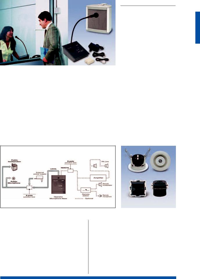
systems |
|
|
|
|
ITC2000-C • Interphone system for counters |
I T C 2 0 0 0 - C |
|||
|
|
|
||
|
|
|
||
|
|
|
The ITC2000-C is an interphone system |
|
|
|
|
||
|
|
|
||
|
|
|
||
|
|
|
for counters for the public. Microproces- |
|
|
|
|
||
|
|
|
|
sor-based management allows high- |
|
|
|
|
|
|
|
|
|
quality flexible performance. The system |
|
|
|
|
|
|
|
|
|
has more than one operating model. It |
|
|
|
|
|
|
|
|
|
|
|
|
|
|
can be configured as a handsfree |
|
|
|
|
|
|
|
|
|
“speak-listen” unit and, if connected to |
|
|
C 4 0 1 - B |
|
|
|
|
|
an amplifier, it can be incorporated |
|
|
|
|
|
|
|
|
|
|
profitably into a sound-broadcasting |
|
|
|
|
|
|
|
|
|
system. This latter application is |
|
|
|
|
|
|
|
|
|
|
|
|
|
|
extremely interesting, since in addition |
|
|
|
|
|
|
|
|
|
to carrying on a conversation over the |
|
|
|
|
|
|
|
|
|
counter, the operator can also make |
|
|
|
|
|
|
|
|
|
announcements to the public or calls to |
|
|
|
|
|
|
zones. These can also be made, with different levels of priority, via the microphones of other operators connected to the system |
|||
|
(i.e. safety personnel, and so on). The ITC2000-C stands out from other “speak-listen” systems available on the market since it |
|||
|
operates in the attenuation mode rather than by switching. This makes the conversation more natural, since the unpleasant breaks |
|||
|
in the dialogue that are typical of switched systems are avoided. The operator station is equipped with a microphone on a flexi- |
|||
|
ble stem, long enough to enable conversation in a natural tone of voice and volume, with no howl-round effects. The system must |
|||
|
be equipped with PASO C401-B loudspeakers on the public side, for listening. These are made of aluminium, are extremely |
|||
|
tough and suitable also for applications requiring protection against vandalism, (e.g. railway and underground, night chemists). |
|||
|
In the back panel there are two standard 3,5 mm jack plugs for connecting headphones and/or external microphone. |
|||
|
The ITC2000-C interphone system consists of the following: |
|
|
|
|
• Microphone base equipped with microphone with anti-hiss- |
• Junction box (telephone type) with 6-pole (female) tele- |
||
|
ing protection |
phone connector |
|
|
|
• External 230 V AC/18 V DC, 500mA power supply |
• Wall-mounted electret microphone, equipped with shielded |
||
|
• Connecting cable between the interphone base and the |
cable (length 3m). This microphone was designed for |
||
|
junction box (length 3 m), equipped with 6-pin (male) tele- |
mounting on the glass pane above the counter, thanks to its |
||
|
phone connectors |
vibration-proof double-adhesive strip. |
||
Note: As an alternative to the C401-B, the models of the EGI range, items nos. G13U/16 or G28N/16 are also available.
Application diagram
G 2 8 N / 1 6
G 1 3 U / 1 6
|
|
T E C H N I C A L S P E C I F I C A T I O N S |
|
|
|
||
M O D E L |
|
|
|
|
IT C200 |
0-C |
|
|
|
|
|
Power-supply voltage/consumption |
15 Vdc/60 mA÷200 mA |
||
Sensitivity of wall-mounted microphone |
-47 dB (0 dB=1V/Pa a 1 kHz) |
||
|
|
|
|
Sensitivity of station microphone |
-48 dB (0 dB=1V/Pa a 1 kHz) |
||
Frequency response (-3 dB) |
270÷8000 Hz |
||
|
|
|
|
Rated output with 8Ω internal loudspeaker |
1 W |
||
Rated output with 8Ω esternal loudspeaker |
1 W |
||
|
|
|
|
Rated output with 16Ω internal loudspeaker |
0.6 W |
||
Size of microphone station (LxHxW) mm |
200x158x81 |
||
|
|
|
|
Net weight of microphone station, kg |
1 |
|
|
|
|
|
|
S Y S T E M S
1.23
 Loading...