

Page 1
DMX 8008
Digital Matrix Mixer
8IN 8OUT
USER MANUAL
ver. 1.2
PRESET /
1 2
3
4
5 6
7
8
MUTE
SGN/CLIP
MUTE
SGN/CLIP
MIC
LINE
MUTE
SGN/CLIP
MUTE
SGN/CLIP
MIC
LINE
MUTE
SGN/CLIP
MUTE
SGN/CLIP
MIC
LINE
MUTE
SGN/CLIP
MUTE
SGN/CLIP
MIC
LINE
1 / 2 / 3 /
5 6 /4 /
PH
DMX8008
SETUP
PageEsc
Page 2
CONTENTS
Safety.............................................................................................................................
1.0 Overview..................................................................................................................
1.1 Main features..............................................................................................................
1.2 Front/rear panel...........................................................................................................
1.3 Wall panel...................................................................................................................
1.4 Connection..................................................................................................................
1.4.1 Inputs......................................................................................................................
1.4.2 Outputs....................................................................................................................
1.4.3 General purpose I/O..................................................................................................
1.4.4 Wall panel DMP8008...................................................................................................
1.4.5 Computer.................................................................................................................
2.0 Operation..................................................................................................................
2.1 Overview....................................................................................................................
2.2 Stand alone mode........................................................................................................
2.2.1 TCP/IP Setup............................................................................................................
2.2.2 USB/RS485 Setup.....................................................................................................
2.2.3 ID RS485 Setup........................................................................................................
2.2.4 Output switch linked setup.......................................................................................
2.3 Remote control mode....................................................................................................
2.3.1 Remote control via wall panel......................................................................................
2.3.2 Remote control via PC software...................................................................................
2.3.2.1 Installing PC software..............................................................................................
2.3.2.2 Starting PC software...............................................................................................
2.3.2.3 Connecting-disconnecting or removing units...............................................................
2.3.2.4 Naming-saving and loading units..............................................................................
2.3.2.5 Changing interface..................................................................................................
2.3.2.6 Setting ID number or IP address...............................................................................
2.3.3 Remote control via iPAD.............................................................................................
3.0 Editing.......................................................................................................................
3.1 Inputs page..............................................................................................
3.2 Outputs page............................................................................................
3.3 Routing page...............................................................................................................
3.4 Overview page.............................................................................................................
3.5 Automixer functions.................................................................................................
3.6 Priority ducker.............................................................................................................
3.7 Background utilities..............................................................................
4.0 Technical specifications............................................................................................
5.0 Block scheme............................................................................................................
6.0 Communication protocol.......................................
DMX 8008
Page 3
|
|
|
<
IMPORTANT SAFETY INSTRUCTIONS
PRECAUTIONS
INSTALLATION
CONNECTIONS
ITEMS SUPPLIED
This product is supplied with the following items:
- AC power cord
- Removable terminal plags
- USB adapter
- Setting software CD with user manual
DMX 8008
Page 4
1. OVERVIEW
The DMX8008 is a high performance 8 input x 8 output digital matrix mixer; specially designed for
commercial and professional applications such as conference rooms, auditoriums, sport utility buildings,
house of worship, pubs and disco. It includes 8 independently switchable Line/Mic inputs with Phantom power
supply, 8 line outputs, managed by a powerful 48kHz / 24 bit DSP engine, in addition to high performance 24
bit AD/DA converters. The DMX8008 supports a full matrix mixing mode where inputs may be routed/mixed
in any ratio to any output. Each Mic/Line input channel provides Lo/Hi pass 1st order filters, 3-band parametric
EQ, Noise Gate function and Gain control. In addition Mic inputs include a Feedback Eliminator function, based
on a powerful «pitch shifting» algorithm, particularly suitable for voice applications. Automixing function
automatically adjusts input level to make operating easier using either NOM (Number of Open Mics)
attenuation function or Gain sharing algorithm. In addition Ducking process enforces a «priority order» of
open microphones in order that high priority inputs attenuate lower priority inputs. Each output offers up to 5band of parametric equalization, crossover filters, RMS compressor, Peak limiter, Phase and Delay controls; 8
digital In/Out ports are provided for general purpose ( preset recall, trigger third parts or device ); 8 front
knobs provides a quickly way to control input Gain; Up to 32 units can be managed by software applications.
1.1 MAIN FEATURES
2
DMX 8008
While thanking you for having chosen a PASO product, we would like to remind you that our company works according to a
certified Quality System. This means that all our products are checked during every phase of manufacturing in order to ensure
that you will be fully satisfied with your purchase. In any case, the guarantee will cover any manufacturing flaws during the
guarantee period. We recommend that you read the following instructions for use and follow them carefully in order to exploit in
full the performance of this product and use it correctly.
Please read this instruction sheet carefully.
PASO S.p.A. will accept no liability for personal injury and/or damage to property resulting from incorrect installation or
improper use of the product. The equipment must be set up by trained personnel. Incorrect installation could result in the risk
of electric shocks.
PASO S.p.A. strive to improve their products continuously, and therefore reserve the right to make changes to the drawings
and technical specifications at any time and without notice.
PRESET /
1 2
3
4
5 6
7
8
MUTE
SGN/CLIP
MUTE
SGN/CLIP
MIC
LINE
MUTE
SGN/CLIP
MUTE
SGN/CLIP
MIC
LINE
MUTE
SGN/CLIP
MUTE
SGN/CLIP
MIC
LINE
MUTE
SGN/CLIP
MUTE
SGN/CLIP
MIC
LINE
1 / 2 / 3 /
5 6 /4 /
PH
DMX8008
SETUP
PageEsc
Page 5
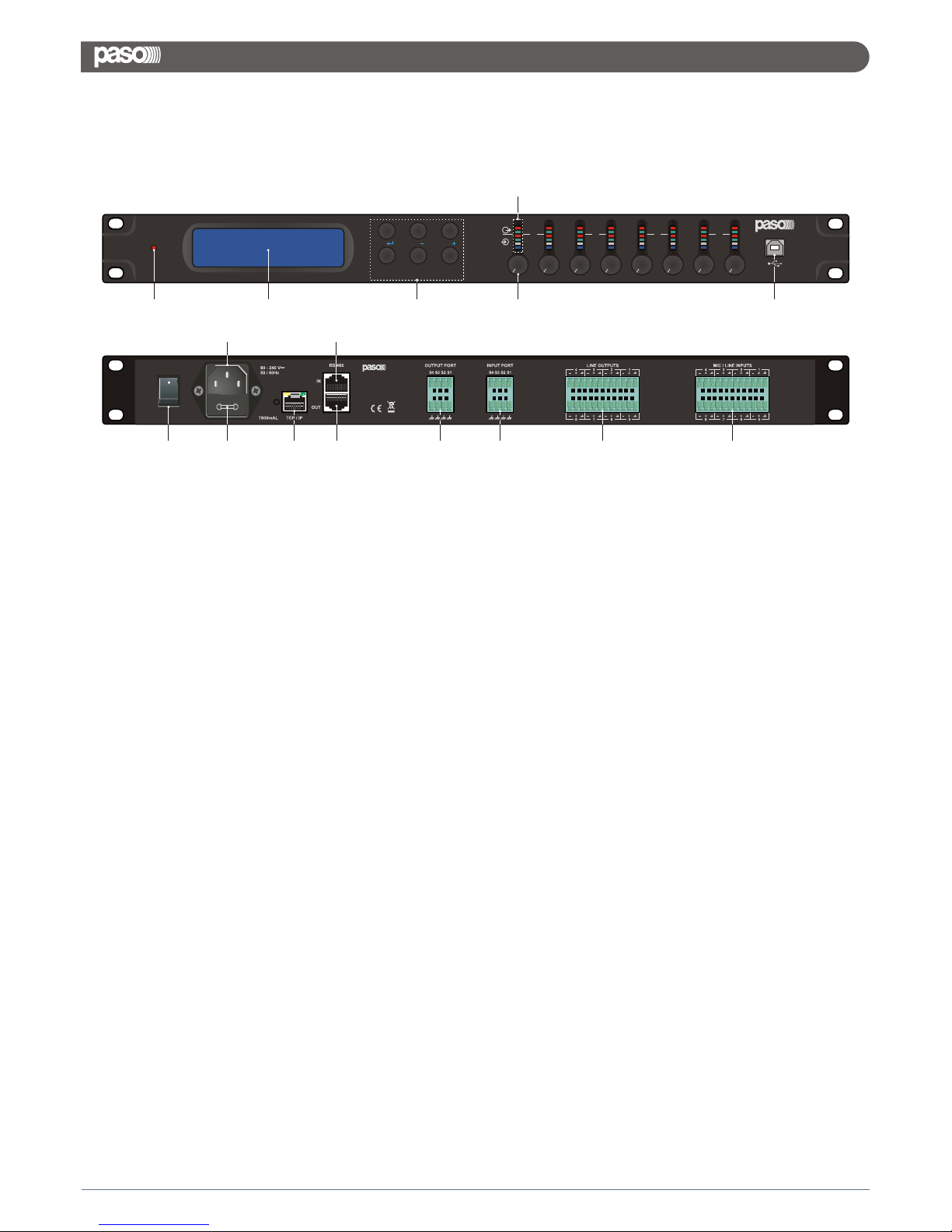
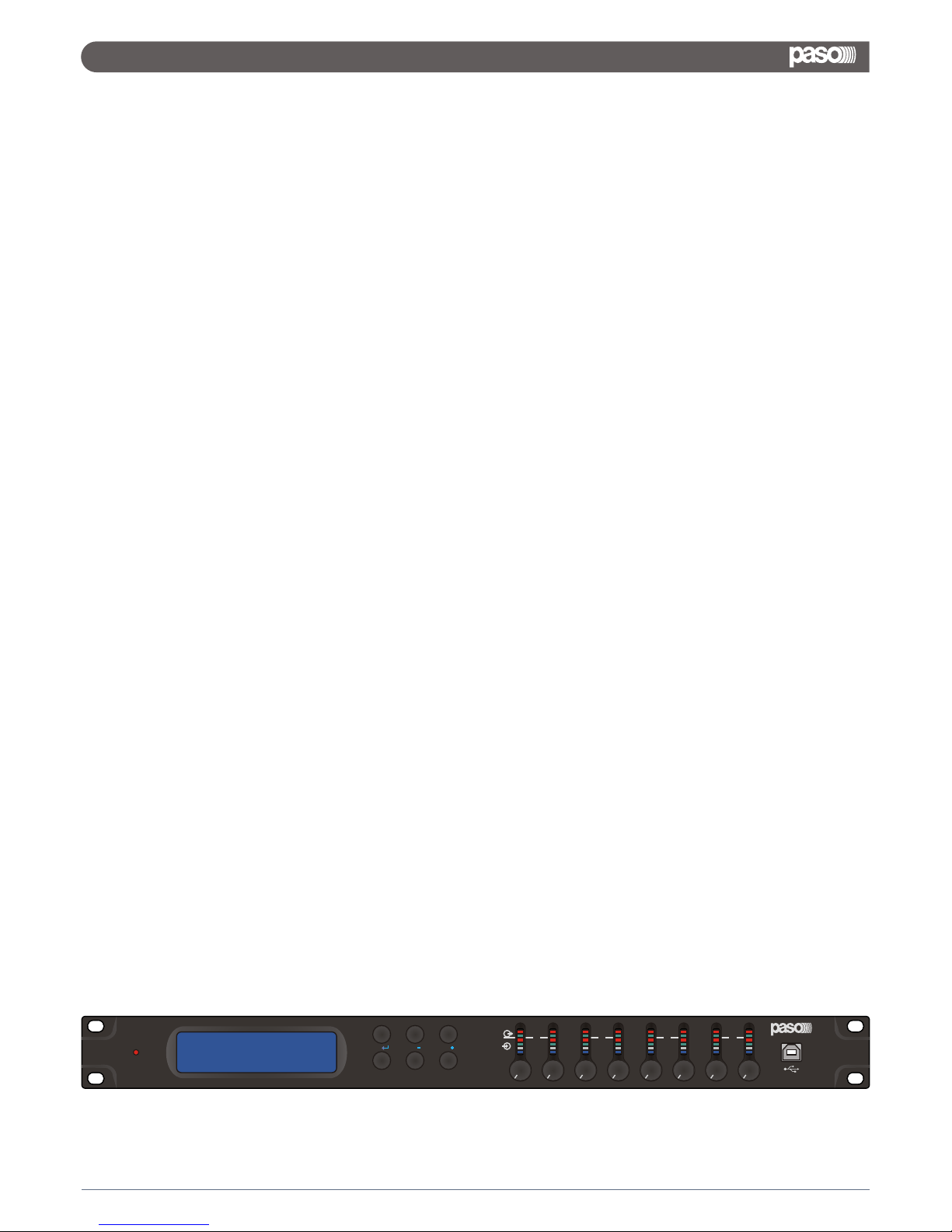
1> LED PHANTOM POWER: lights up when the phantom power supply for the microphone inputs is switched on
2> 2 x 24 LCD display
3> Buttons PRESET 1/6: for retrieving the configurations previously saved; to call up the system setting menu
4> Status LEDs for the input/output channels:
Ch1 - Ch8:
MUTE - output mute condition
SGN/CLIP - output signal (blink in clip condition)
MUTE - input mute condition
SGN/CLIP - input signal (blink in clip condition)
MIC - input set as Mic
LINE - input set as Line
5> Mic input channel knob: allow to increase/decrease the gain of the mic inputs
6> USB jack type B: to connect a computer for remote control and for configuration of the DMX8008
7> POWER switch
8> Mains jack: for connection to a socket (90-240Vac / 50-60Hz) via the mains cable supplied
9> Support for the mains fuse; always replace a blown fuse by a fuse of the same type
10> RJ45 jack TCP/IP: to connect a computer for remote controlled operation of the DMX8008 via Ethernet; the two LEDs
above the jack indicate that the connection is being established or that data is being transferred
11> RJ45 jack RS485 IN: to connect a computer for remote controlled operation or to connect the remote control panel
DMP8008
12> RJ45 jack RS485 OUT: to connect an additional unit to be remote controlled by the computer that is connected to jack
RS485 IN
13> Switching outputs S1 - S4 as screw terminals
14> Switching inputs S1 - S4 as screw terminals to retrieve the extra configurations previously saved
15> Balanced audio signal outputs Ch1 - Ch8 as screw terminals
16> Balanced audio signal inputs Ch1 - Ch8 as screw terminals
1.2 FRONT / REAR PANEL
3
DMX 8008
PRESET /
1 2
3
4
5 6
7
8
MUTE
SGN/CLIP
MUTE
SGN/CLIP
MIC
LINE
MUTE
SGN/CLIP
MUTE
SGN/CLIP
MIC
LINE
MUTE
SGN/CLIP
MUTE
SGN/CLIP
MIC
LINE
MUTE
SGN/CLIP
MUTE
SGN/CLIP
MIC
LINE
1 / 2 / 3 /
5 6 /4 /
PH
DMX8008
SETUP
PageEsc
ON
DMX8008
DIGITAL MATRIX MIXER
MADE IN CHINA
CAUTION:
TO REDUCE THE RISK OF FIRE,
REPLACE FUSE WITH SAME TYPE
AND RATING.
DISCONNECT POWER SUPPLY CORD
BEFORE CHANGING FUSE.
OFF
1 2 3
4
5 6
7 9
8 11
10 12 13 14 15 16
Page 6
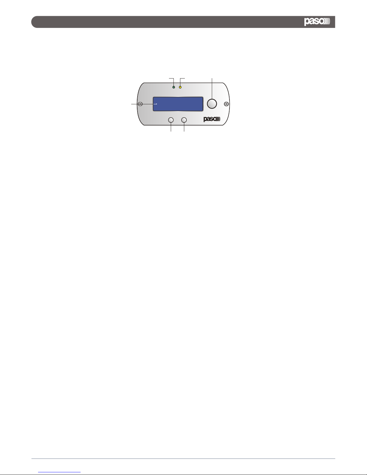
1.3 WALL PANEL
17> 2 x 16 LCD display
18> SET button allows to confirm the selection
19> ESC button allows to come back without confirm
20> Encoder allows to scroll available selections
21> Power indication LED
22> RS485 indication LED
4
ETH
SET
ESC
PWR
17
18 19
21 22 20
DMX 8008
Page 7

1.4 CONNECTION
1.4.1 INPUTS
Connect line-level signal sources, e.g. the output of a preamplifier or of a mixer, to the screw terminals INPUTS
CH1-CH8 (16). The connections are provided for balanced signals. To connect unbalanced signal sources,
connect the contacts «-» and «gnd». Alternatively, connect microphones to these terminal screws. Use the
computer to configure the respective input as a microphone or line input. This procedure can also be used to
provide all microphone inputs with a phantom power supply of 48V. In this case, only microphones with
balanced signal outputs can be connected. Microphones with unbalanced outputs may be damaged by the
phantom power supply.
1.4.2 OUTPUTS
Connect the amplifiers, monitoring systems or other units for further signal processing to the screw terminals
LINE OUTPUTS Ch1 - Ch8 (15).
1.4.3 GENERAL PURPOSE I/O
Use the four switching inputs to retrieve special configurations (extra programs). Connect the units that are to
be used as switching units to the screw terminals INPUT PORT "S1" to "S4" (14) and the corresponding ground
terminals. A switching voltage of +5V is required. The logic type and the priority between the four inputs can
be configured via the computer. Four switching outputs with a switching voltage of +5V are available for
controlling other units. Connect the switching inputs of these units to the screw terminals OUTPUT PORT "S1"
to "S4" (13) and the corresponding ground terminals "gnd".
1.4.4 WALL PANEL DMP8008
The wall mount control panel DMP8008 (separately available as an option) allows users to operate the
DMX8008 by two configurable modes: Zone controller (only a single zone can be managed) and Global
controller (can be managed all inputs and outputs).
Connect the terminals "485+" and "485-" located on the rear side of the operating panel to the appropriate
contacts of the jack RS485 IN (11); to supply power to the control panel, connect the terminals "+12V" and
"GND" to a regulated, unearthed DC voltage source of 12V (observe the correct polarity !).
Note: in order to enable the control panel to establish a data connection to the DMX8008, only switch on the
power supply for the control panel when the DMX8008 has already been switched on.
1.4.5 COMPUTER
To operate the DMX8008 by remote control via a computer, connect the computer to the jack (6) using a USB
cable. Alternatively, the unit may also be controlled via the RS485 interface (provided the interface is not to be
used for connecting the control panel DMP8008) or Ethernet. To control the DMX8008 via the RS485 interface
connect the RS485 output of the computer to the jack RS485 IN (11); the pin confiduration is:
The output jack RS485 OUT (12) may be connected to the jack RS485 IN of an additional
DMX8008. Thus, up to 64 units to be controlled may be connected in a chain. If multiple units
are connected and if longer control lines are used, the control output of the last unit in the chain
should be equipped with a terminal resistor (120 Ohm resistor between pin 1 and pin 2 of the
connection) to prevent interference while signals are transmitted.
To operate the DMX8008 by remote control via Ethernet, the jack TCP/IP (10) may be used to
connect the DMX8008 to an individual computer, a local computer network or, e.g. via a router, to larger
computer networks (internet). Network technology expertise is indispensable for the correct installation of the
connection.
5
1 8
8 1 1= RS485+
2= RS485-
DMX 8008
Page 8
The DMX8008 can work as a stand alone unit [Stand Alone Mode], where up to 6 preset can be recalled by directly selecting
them through the 6 “preset” buttons available on the front panel, or an work as completely remotely controlled unit [Remote
Control Mode].
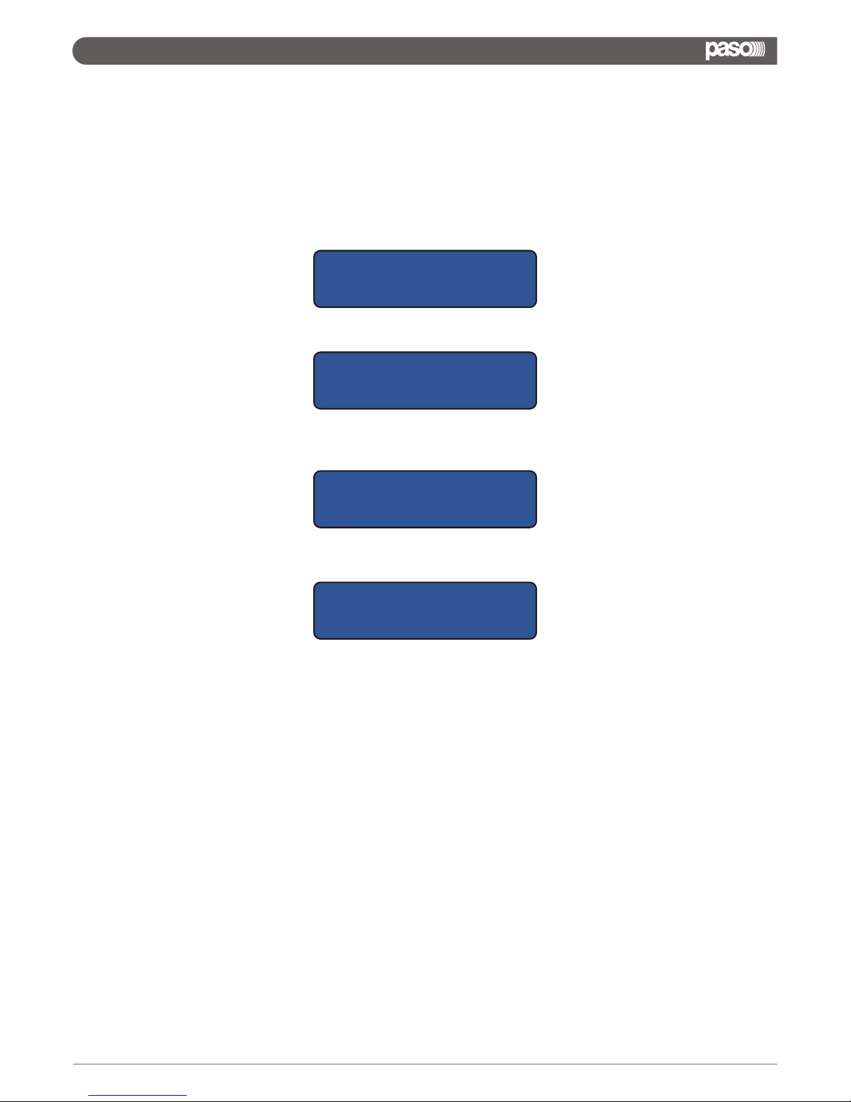
As soon as is turned ON the device will indicate the current Firmware version
and then will load the currently selected preset.
During the Preset Loading, the LCD screen will show the following:
Here the unit is just checking if Presets are available on the Eeprom.
If not, the “Init” phase can last several seconds, and the Eeprom of the unit is initialized in order to guest later on the presets will
be created by the user through the Pc Remote Control Sw.
If Presets are already available, then the “init” phase will be skipped and the currently selected preset will be loaded.
The preset loading can take approximately 14Seconds and will end with showing on the LCD the currently running preset's
name:
2. OPERATION
2.1 OVERVIEW
6
DMX 8008
DMX8008
Firmware version V1.x
Please Wait.....
Loading new program.....
DMX8008
01: Program default
DMX8008
01: Current Preset Name
Page 9
PRESET /
1 2
3
4
5 6
7
8
MUTE
SGN/CLIP
MUTE
SGN/CLIP
MIC
LINE
MUTE
SGN/CLIP
MUTE
SGN/CLIP
MIC
LINE
MUTE
SGN/CLIP
MUTE
SGN/CLIP
MIC
LINE
MUTE
SGN/CLIP
MUTE
SGN/CLIP
MIC
LINE
1 / 2 / 3 /
5 6 /4 /
PH
DMX8008
SETUP
PageEsc
When the DMX8008 is operating as stand alone unit, so running one of the 6 available presets, previously
created and stored within the unit with the remote control Pc Sw, the only available control are the 6 “preset
buttons”, allowing to select 1 of the 6 available presets previously stored through the Pc Sw Remote Control.
The name of the currently loaded/running preset is displayed on the LCD screen.
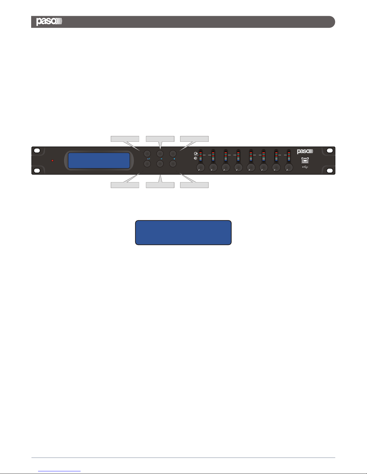
Using the buttons on the front panel, a particular function called System Setup, can be accessed.
For accessing the System Setup function, need to refer to the 6 available buttons on the front panel, as follow:
Referring to the Picture, in order to access the System Setup need to press the Button 5 / Utilities, for about 4
seconds,
The following window will appear:
As the picture shows, in the System Setup mode the buttons 1/2/3/4/6 are used as Enter/Down/Up/Esc/Page
commands, used for scrolling, accessing and editing the following 5 Menus:
1. Tcp/Ip Setup
2. Output Switch Linked
3. Out Switch Setup
4. ID RS485 Setup
5. USB/RS485 Setup
From the first “Tcp/Ip Setup” Menu, just using the Up/Down buttons, the all other Menus can be accessed.
1 / Enter 2 / Down 3 / Up
4 / Esc 5 / Utilities 6 / Page
2.2 STAND ALONE MODE
7
DMX 8008
System Setup
----- Tcp/Ip Setup -----
Page 10
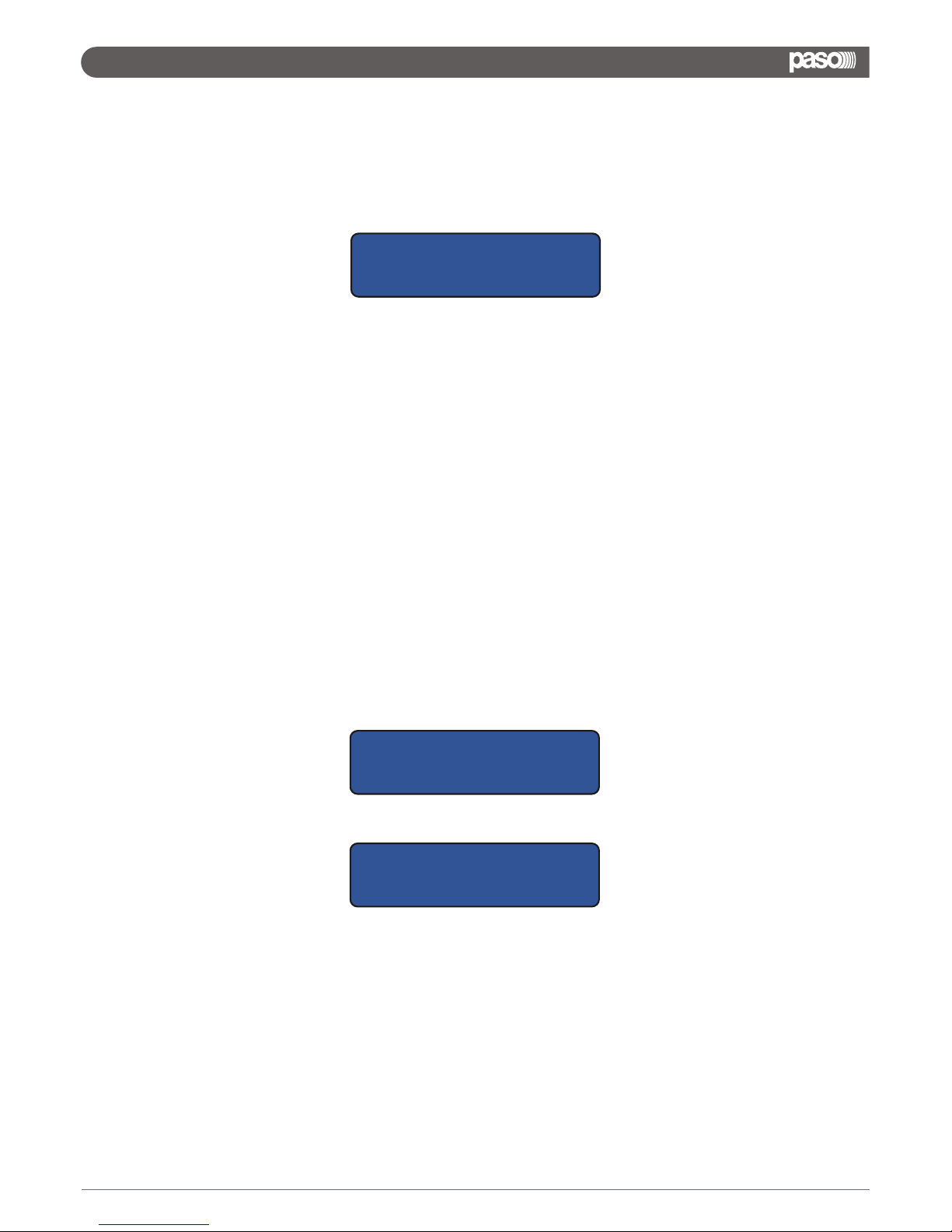
Within this Menu, the User can set the DMX8008 IP Address
From the Tcp/Ip Setup, pressing the Button 1 / Enter, the following sub-menu is entered:
Here, the first digit of the IP will be blinking, which means the User can modify the digit's value using the
Up/Down buttons.
Once assigned the desired value to the digit, confirm it pressing the Enter button.
After a while, the system will automatically go to the second digit of the IP address, which will start blinking.
With the Button Page, a digit can be skipped without being modified, so using Page is possible to scroll into the
all 4 digits of the IP Address, without the necessity to modify them.
The first digit of the IP Address can range from 1 to 223, the second and third digits can range from 0 to 255
and the fourth digit from 1 to 255.
The system will automatically compute the right “Sub Net Mask” value to assign to the Unit, once defined the
IP address.
The Sub Net Mask values are the following:
1. IP Address from IP=001.0.0.2 up to IP=126.255.255.254, SubNetMask = FF000000h (Class A)
2. IP Address from IP=127.0.0.2 up to IP=191.255.255.254, SubNetMask = FFFF0000h (Class B)
3. IP Address from IP=192.0.0.2 up to IP=223.255.255.254, SubNetMask = FFFFFF00h (Class C)
Once set properly the IP Address, the Tcp/Ip setup Menu can be left using the Esc button.
Within this Menu, the User can chose between the USB or RS485 connection type to be used for a remote
control.
From the USB/RS485 Setup page
pressing the Button 1 / Enter, the following sub-menu is entered:
Here, the communication interface to be used can be selected: USB/RS485/Automatic.
The Tcp/Ip connection is EVER available.
In the USB mode, the DMX8008 can be controlled via USB interface or via Tcp/Ip connection.
If selected, the USB interface will be active as default when the DMX8008 is turned ON.
In the RS485 mode, the DMX8008 can be controlled via USB interface or via Tcp/Ip connection.
If selected, the RS485 interface will be active as default when the DMX8008 is turned ON.
If selected the Automatic Mode, the unit will continuously “switch” between USB and RS485 (each about
100ms), looking for an available Remote Control on one of the 2 interfaces.
Once found an available one, the DMX8008 will communicate via the interface corresponding to the one found.
If selected, the Automatic interface will be active as default when the DMX8008 is turned ON.
The currently active connection type, will be displayed on the extreme right of the LCD's top row, with the
U/R/A symbols (USB/RS495/Automatic).
USB/RS485 Setup
Mode = USB
2.2.1 TCP / IP SETUP
2.2.2 USB / RS485 SETUP
8
DMX 8008
Tcp/Ip Setup
IP=192.168.000.001
Tcp/Ip Setup
IP=192.168.000.001
System Setup
----- USB/RS485 Setup -----
Page 11
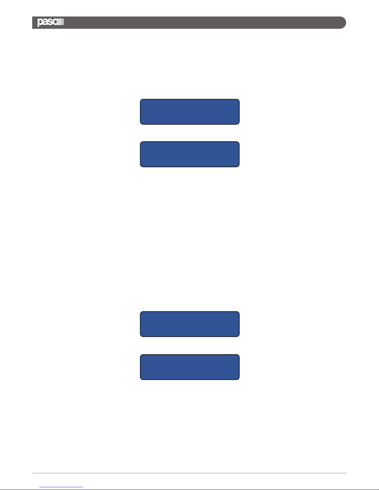
Within this Menu, the User can define the ID of the DMX8008 when working with a remote control via RS485
interface.
From the ID RS485 Setup page
pressing the Button 1 / Enter, the following sub-menu is entered:
Here, the ID number of the DMX8008 can be assigned.
The possible ID values range from 1 to 64.
The ID number can be selected using the Up/Down buttons.
The Enter button has to be used to SAVE the assigned ID number and exit the Menu.
The Esc button has to be used to exit the Menu WITHOUT SAVING the ID number.
The DMX8008 has internally the possibility to store up to 10 Presets “Switch” (Only by Pc Sw) and on each one
of these presets is contained the Status of the Output Switch lines (Output Ports S1/S2/S3/S4) available on
the DMX8008 back panel.
These 10 presets can be recalled in LINK with the corresponding “Audio”Preset, by pressing one of the 6
Presets Buttons of the front panel (or just loading the presets by Pc), once the Output Switch Link function is
set as ON.
In this case, any time an Audio Preset is recalled by pressing one of the front panel's buttons, the equivalent
Switch preset Is also loaded: it the Audio Preset N. 1 is recalled, the Switch preset N. 1 is recalled too.
In a such case, each recalled preset is a combination of an Audio and a Switch preset.
To get the above result, need therefore to enter the System Setup's Output Switch Linked page
And to set as On the Link
If the Output Switch Linked is not active and the Switch presets aren't linked to the Audio ones, they'll not be
recalled once pressed any one of the Preset Buttons.
Therefore, the Switch Outputs status can be “manually” defined by the User who will be allowed to recall
“manually” one of the 10 Switch preset and leave it active until a new “Manual” setting or a change of the
Output Switch Linked Status.
System Setup
----- ID RS485 Setup -----
ID RS485 Setup
ID = 1
System Setup
----- Output Switch Linked -----
OUTPUT SWITCH LINKED
Link = ON
2.2.3 ID RS485 SETUP
2.2.4 OUTPUT SWITCH LINKED SETUP
9
DMX 8008
Page 12

If the Output Switch Linked mode is set with Link = OFF, the User can “Manually” Load one of the 10 switch
Presets available and previously created using the Pc Sw.
This can be done from the Out Switch Setup Menu
Within this Menu, the User can select and Load one of the 10 available Switch Presets.
Pressing the Button 1 / Enter, the following sub-menu is entered:
Here, the user can recall one of the 10 available Switch Presets SP01-SP10, just selecting the
desired one by the Up/Down buttons.
As said, in this way any action on the Preset Buttons, forcing the Load of the corresponding Audio Preset, will
not affect the status of the Output Switches, which will depend from the Preset loaded “Manually” by the User
within the Output Switch Setup, being the Output Switch Linked Status set as OFF.
In order to finally leave and exit the System Setup mode, so to get back to normal working mode, is is enough
to get back to any one of the 5 System Setup Menus and there from press the ESC button.
NOTE: The All Settings done within the System Setup Function will be effective ONLY WHEN LEFT the System
Setup Mode itself.
Within the System Setup Mode, the all communications with the remote control units are DISABLED, so as the
some “Real Time” processes available in the DMX8008.
In Stand Alone Mode, the “Activity” of the DMX8008 in terms of running processes and signal status, per each
channel, can be checked thanks to the Vu-Metering features:
1 led for Microphone Phantom Power Supply Active
5 led for Outputs Activities:
System Setup
----- Out Switch Setup -----
OUTPUT SWITCH SETUP
SP01
10
DMX 8008
Page 13
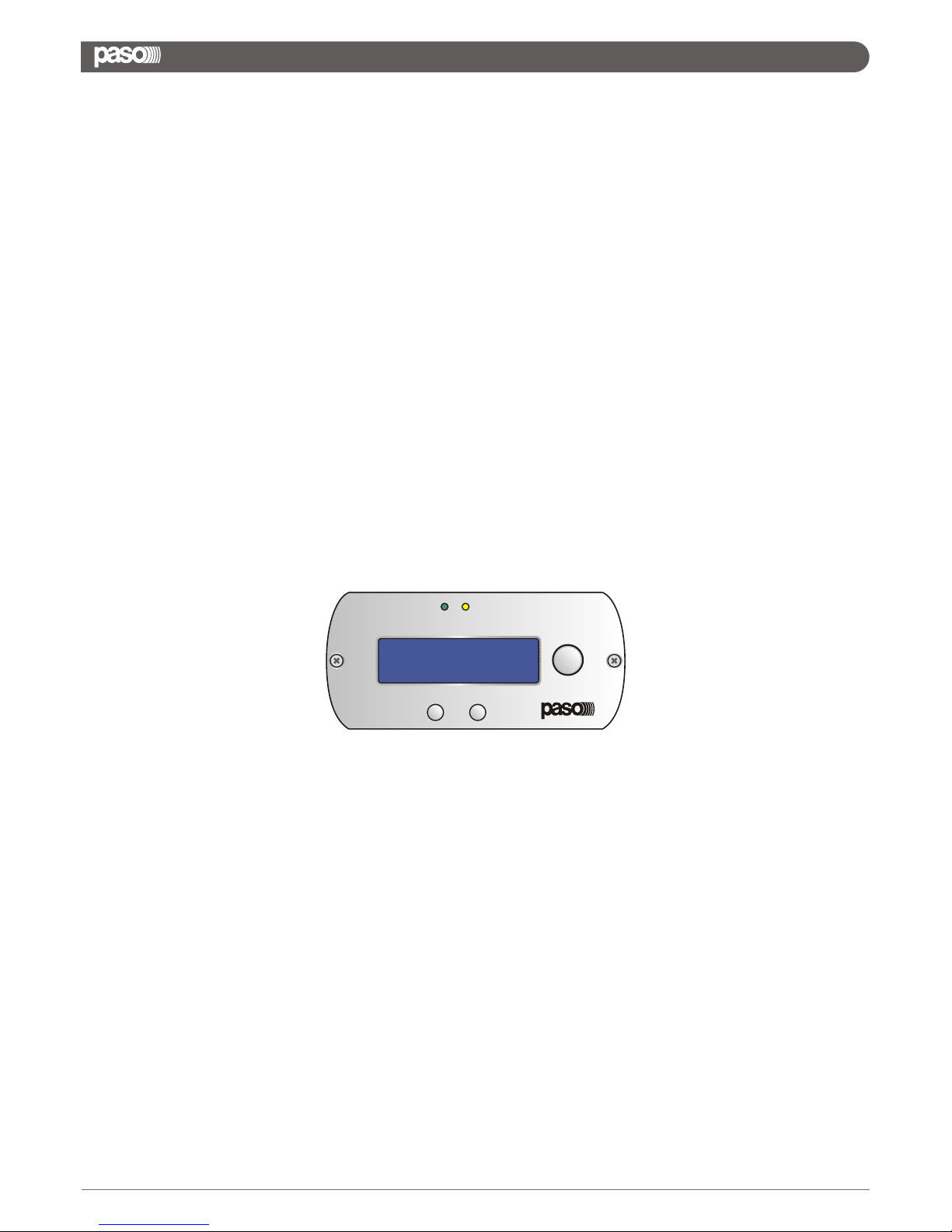
The DMX8008 is mainly thought to operate with Remote Control Sw running on Pc.
Nevertheless, once created the desired presets for the defined applications, the unit can operate as a Stand
Alone one, as seen before or as Wall Panel Remote Control working device.
The Remote control, when operated by the Wall Panel Remote control, is working on the base of the RS485
connector of the DMX8008
The Pc Sw remote control, can instead operate with USB, RS485 or Tcp/Ip connection.
When used the USB connection, the Pc Sw Remote Control can control/edit ONLY one unit per time.
When used the RS485 or Tcp/Ip connection, the Pc Sw Remote Control can control/edit MORE units at the
same time, connected each others in net.
Particularly, with the Tcp/Ip connection and using an external standard router, the DMX8008 can even be
controlled through a complete iPad remote control Sw.
A particular way of “double” Remote Control is allowed, being possible to connect to the Rs485 the Wall Panel
Control and at the same time the Pc Sw Remote Control can be used if connecting the Pc on the USB
connection.
The wall mount control panel DMP8008 (separately available as an option) allows users to operate the
DMX8008 by two configurable modes: Zone Controller (only a single zone can be managed) and Global
Controller (can be managed all inputs and outputs).
DMP8008 set as Zone Controller allow to:
- Adjust local output gain
- Set local mute
- Inputs selection
- Select lock condition
- View system info
DMP8008 set as Global Controller allow to:
- Adjust every inputs/outputs gain
- Set every inputs/outputs mute
- Recall presets stored
- Select lock condition
- View system info
2.3 REMOTE CONTROL MODE
2.3.1 REMOTE CONTROL VIA WALL PANEL
11
DMX 8008
ETH
SET
ESC
PWR
Page 14
2.3.2 REMOTE CONTROL VIA PC SOFTWARE
The computer software supplied can be used to operate the DMX8008 by remote control. Thus, the unit may
also be configured for operation without a computer. The configurations created may be saved on the unit or on
the computer.
2.3.2.1 INSTALLING PC SOFTWARE
The installation of the control program supplied requires a PC equipped with the WINDOWS XP operating
system (SP2) or later, a memory of at least 512MB, 10MB free hard-disk space and a USB, Ethernet or RS485
interface. The screen resolution should be at least 1024x768 pixel.
To install the PC software, start the installation program "SETUP.EXE" on the CD supplied and follow the
instructions of the installation program.
The connection via the USB interface or the Ethernet interface requires a special driver which is included on the
CD supplied. Call up the file USB[...]SETUP.EXE to install the driver automatically. The driver will simulate a
serial interface for the operating software.
2.3.2.2 STARTING PC SOFTWARE
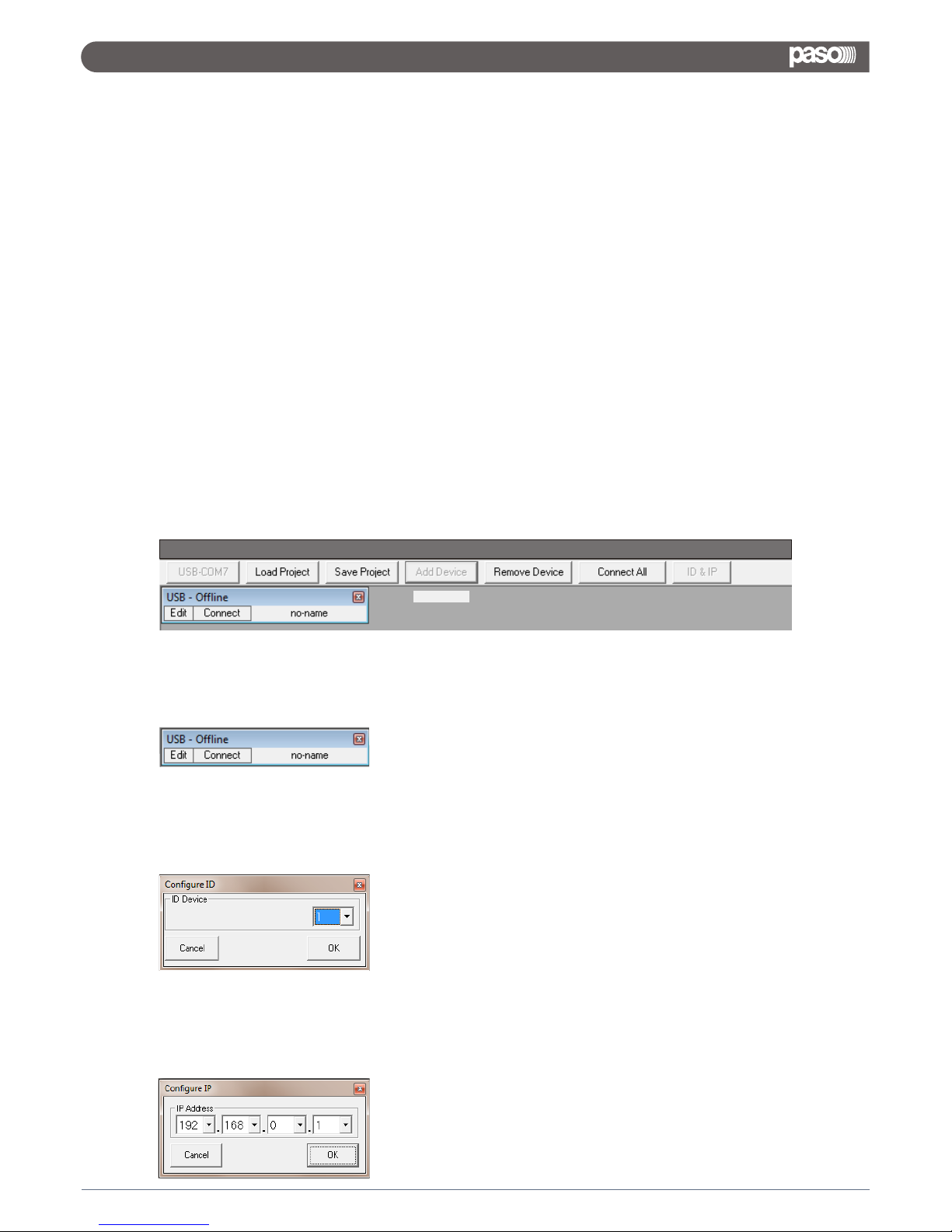
Start the control program DMX8008 Vx.x.x on the PC. The main window (fig.1) appears, showing the units that
were most recently connected. For each unit, a separate window is provided: the header shows information
with regard to the interface as well as the connection status.
Fig.1
To add a(nother) unit, click the button "Add Device".
If USB is selected as the current interface type (the text on the button on the upper left is "USBCOMx"), the
following unit window will be displayed:
Add Device
After that, it is not possible to add further units.
If RS485 is selected as the current interface type ( the text on the button on the upper left is "RS485-COMx",
the following dialog window will initially be displayed:
Select the unit number (ID) of the unit desired and then press "OK" to confirm.
If Ethernet is selected as the current interface type (the text on the button on the upper left is "TCP/IP"), the
following dialog window will initially be displayed:
Enter the IP address of the unit desired and then press "OK" to
confirm. For each unit, a separate window is added.
12
DMX 8008
DMX8008
Page 15
2.3.2.3 CONNECTING - DISCONNECTING OR REMOVING UNITS
13
DMX 8008
Page 16
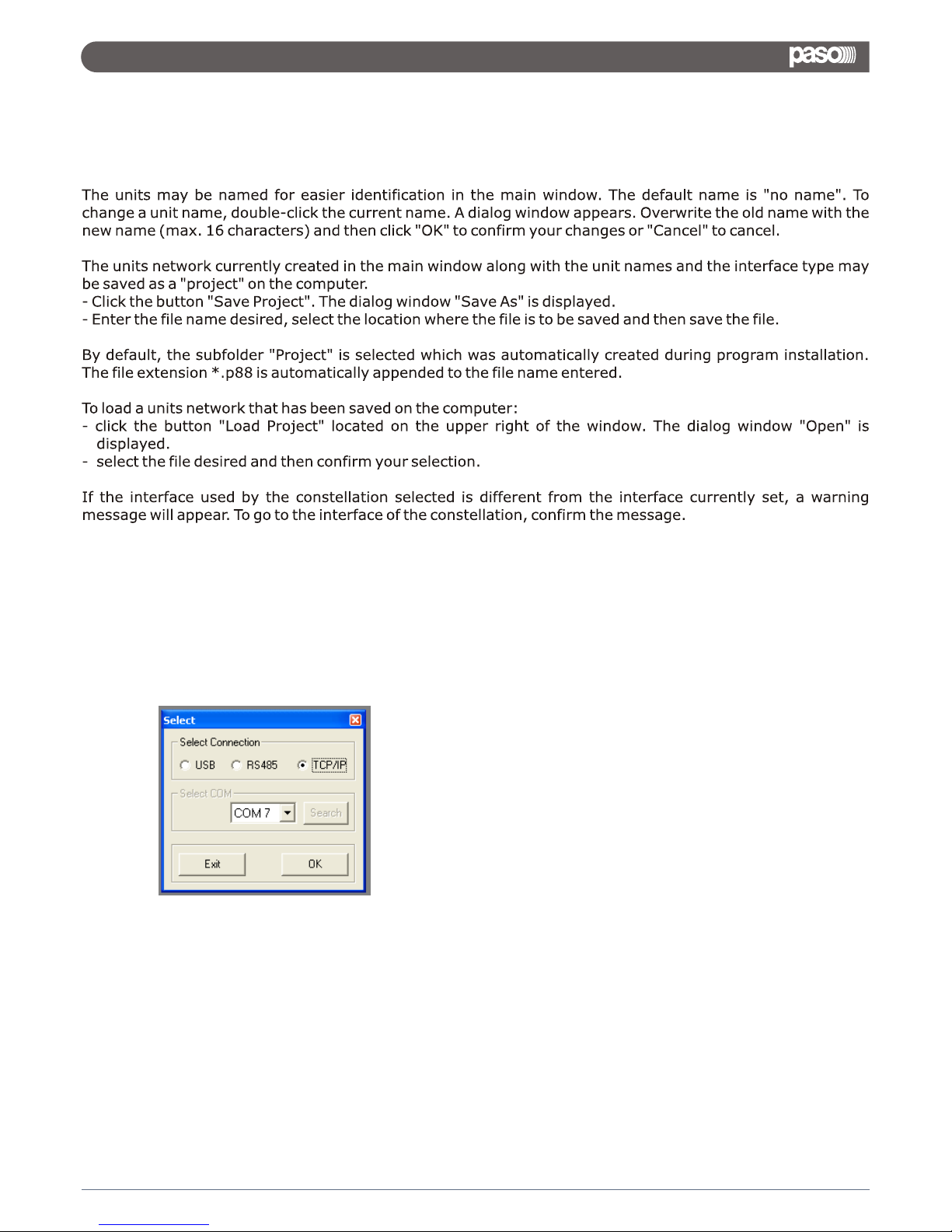
2.3.2.4 NAMING - SAVING AND LOADING UNITS
2.3.2.5 CHANGING INTERFACE
To change to one of the other interface types supported, first remove all units from the main window then:
- click the button on the upper left. Depending on the interface currently selected, the text on the button is
"USB-COMx", "RS485-COMx" or "TCP/IP".
The following dialog window is displayed:
- Under "Select Connection" select the interface desired ("USB", "RS485" or "TCP/IP").
- For "RS485" the number of the port used for this interface must be selected under "Select COM". For "USB"
the serial interface that simulates the driver for this software must be selected under "Select COM". Check
the settings of the operating system for the appropriate COM interface or use the button "Search" to have it
determined automatically.
The respective settings of the operating system can for example be found under: _ Control Panel_System
Properties (Hardware)_Device Manager_Ports (COM and LPT).
If there are conflicts with other units, the number of the COM interface may be changed here (e.g.
via_Properties_ Port Settings_Advanced...).
Note: To avoid communication problems, it is recommended to manually change the COM numbers 10 and
higher that are automatically assigned by the computer to the COM numbers 1 to 9.
14
DMX 8008
Page 17

2.3.2.6 SETTING ID NUMBER OR IP ADDRESS
To operate multiple routers DMX8008 by remote control via RS-485 or TCP/ IP, a separate ID number or IP
address must be assigned to each unit prior to their first simultaneous operation. This may be done in the
system menu or, as described in the following, via the computer:
Connect the units one after another to the PC, using the USB interface, and make the following settings for
each unit:
- If the USB interface is not being selected, use the main window to go to the USB interface
- Add a unit (button “Add device” )
- Connect the unit (button “Connect”)
- For remote control via RS-485, press “ Add Device” and select an ID number (1 – 64) under “Configure ID”.
- For remote control via Ethernet, press “ Add Device” define an IP address under “Configure ID”.
A network mask will automatically be generated
2.3.3 REMOTE CONTROL VIA iPad
The DMM8008xT App has been designed for the remote control by iPad of the DMX8008.
The application could be free downloaded from the Apple Store and it offers the same control features ( with
different graphic interface ) available on PC software.
One launched , the application will start scanning the network in order to detect the presence of DMX8008. If
no units will be detected, then the iPad will ask if to continue in OFFLINE MODE or close. In OFF LINE MODE, the
all functions of the DMX8008 can be seen and checked in their full functionality and parameters' range.
If a DMX8008 is instead active and detected in the scanned network, then their assigned Name, IP Address,
will be shown in the screen and make available to the user for the connection.
Until the user will not decide to connect the detected units, their presence will be noticed, but no editing action
can be taken on them. From this Window, any time can be asked a new scanning (Scan Devices) in order to ask
the detection of new units connected to the network, or to identify the removal of one or more of them. Once
decided on which ones of the available units on the network to operate, editing their parameters, need to
connect them to the iPad pressing the “Connect” buttons: the units now are connected and their connection
will be stated on the Status Column. In order to work on the connected units, it is enough to press the related
“Open” buttons and the editing windows will be available and accessible selecting the related icon on the
bottom of the screen, aside the “Home” icon, ever representing the Main Scanning Window.
15
DMX 8008
Page 18
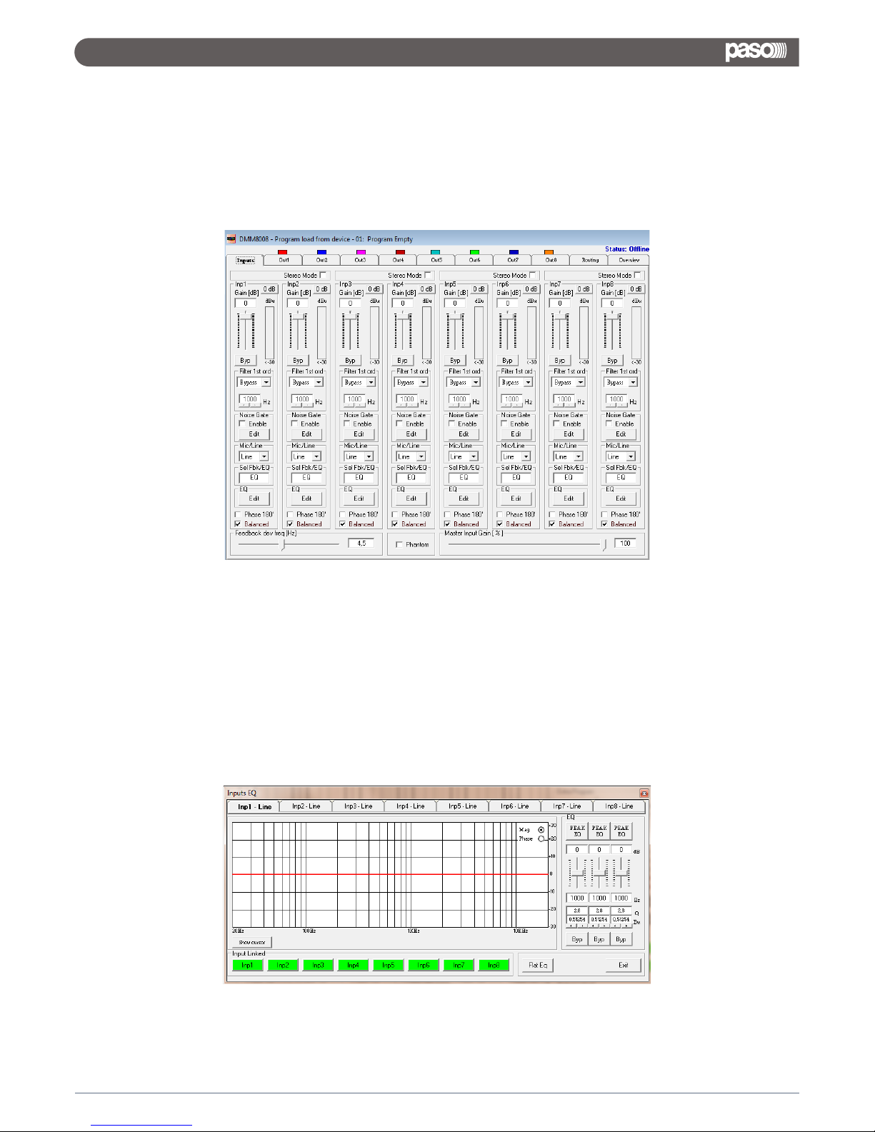
From the “Input” Page of the editing environment, on each input can be selected the source.
This can be Microphone or Line.
When the Line Source is selected, the Input Gain can be adjusted from -127dB up to +12dB.
A Bypass button is available for any channel, allowing to “Bypass” the channel's level setting and bringing
it to 0dB.
A Master input Gain can be used to Mute the all Inputs (0%) or to bring all of them to a level up to 0dB
(100%): each time the Gain Slider is halved in percentage, the Level of each Input is decreased of -6dB.
For each input, is possible to set the signal Phase as “Direct” (unchecked box) or 180Deg.
Reversed (box checked).
A 3 bands Equalizer is ever available and can be set pressing the “Edit” button.
In a such case, the following Eq editing window will open
EQ: from this sub-frame it is possible to set the Input Channels three available Peaker (Bell) or variable Q
Shelving Filters.
3. EDITING
3.1 INPUTS PAGE
16
DMX 8008
Page 19
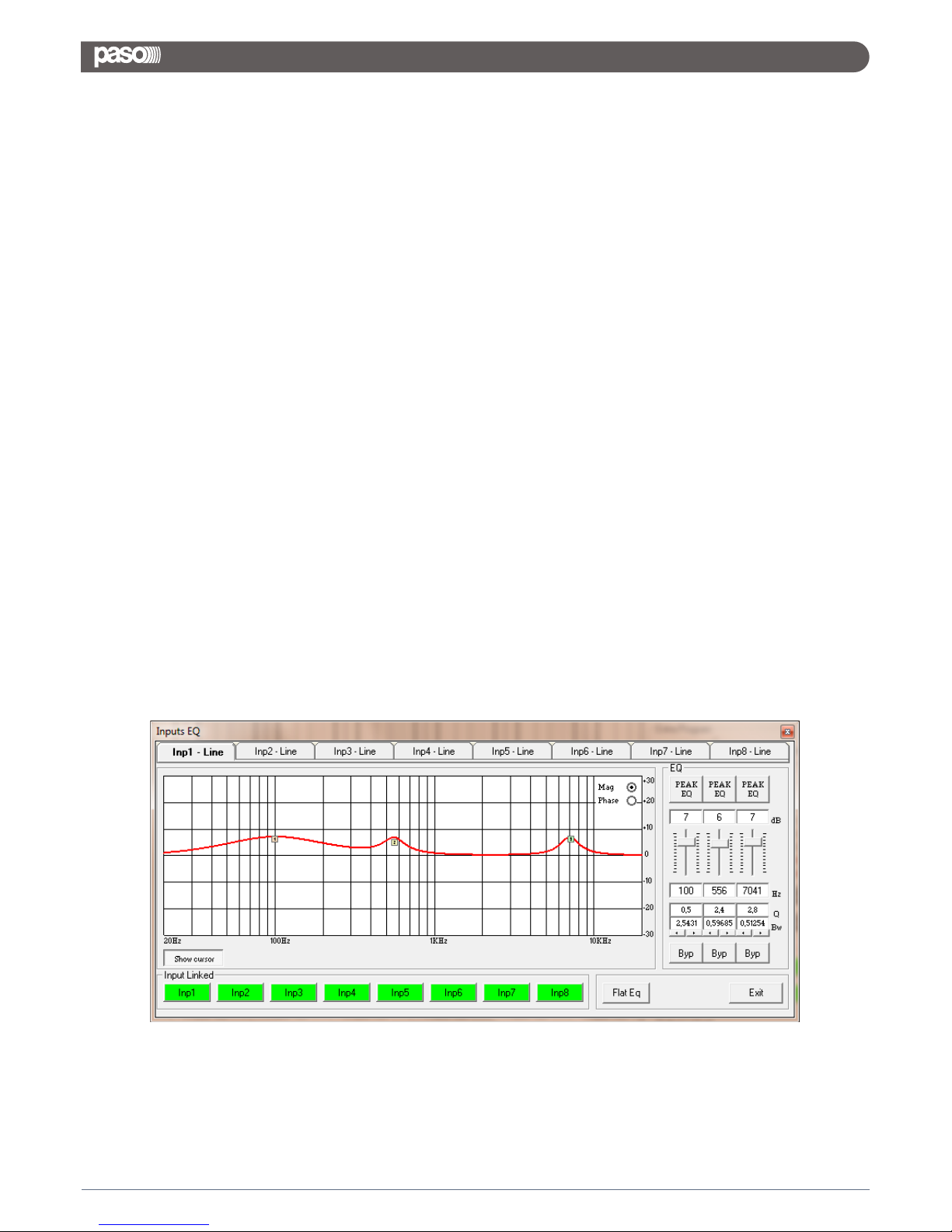
The DMX8008 allows the user to select either Bell or variable Q Shelving Parameters and assign them
independently using the 3 available filters.
The selection can be done just pressing the “Peak Eq” button on top of the filters' gain sliders and selecting one
of the 3 available filters' type: Peaker, variable Q high Shelving and variable Q low Shelving.
BELL Filter: here Center Frequency, Band Width (Q) and Gain can be adjusted.
“Center Frequency”: the selectable frequencies range is from 20Hz to 20kHz in steps of 1/24 of
an Octave.
“Bandwidth BW”: the selectable BW range is from 0.0312 Octave (Q=10) up to 3.59 Octave
(Q=0.4) in steps of 0.1 Q.
“Gain”: the selectable Gain range is from -12dB to +12dB in steps of 0.5 dB.
Variable Q Low Shelving Filter: here Center Frequency, Band Width (Q) (Slope) and Gain can be adjusted.
“Center Frequency”: the selectable frequencies range is from 20Hz to 20kHz in steps of 1/24 of an Octave.
“Bandwidth BW (Slope)”: the selectable BW range is from 0.0312 Octave (Q=10) up to 3.59 Octave
(Q=0.4) in steps of 0.1 Q.
“Gain”: the selectable Gain range is from -12dB to +12dB in steps of 0.5 dB.
Variable Q High Shelving Filter: here Center Frequency, Band Width (Q) (Slope) and Gain can be adjusted.
“Center Frequency”: the selectable frequencies range is from 20Hz to 20kHz in steps of 1/24 of an Octave.
“Bandwidth BW (Slope)”: the selectable BW range is from 0.0312 Octave (Q=10) up to 3.59 Octave
(Q=0.4) in steps of 0.1 Q.
“Gain”: the selectable Gain range is from -12dB to +12dB in steps of 0.5 dB.
Note: each single filter can be independently “bypassed” for an easy setting/use of them.
To “Bypass” the single filter, just press the “Bypass” button below the filter’s parameters.
In order to set, if necessary, more Eq of the 8 input channels in the same way, “Input Linked” buttons are
available and, when pressed, force the all channels corresponding to the pressed buttons to set the Eq in the
same as as the one set for the currently edited channel (which has to be one of the linked ones)
The set up of the filters and specially their frequency placement can also be done with the use of the mouse,
just activating the “Show Cursor” function, pressing the related button on the left bottom of the frequency
response Graphic.
17
DMX 8008
Page 20
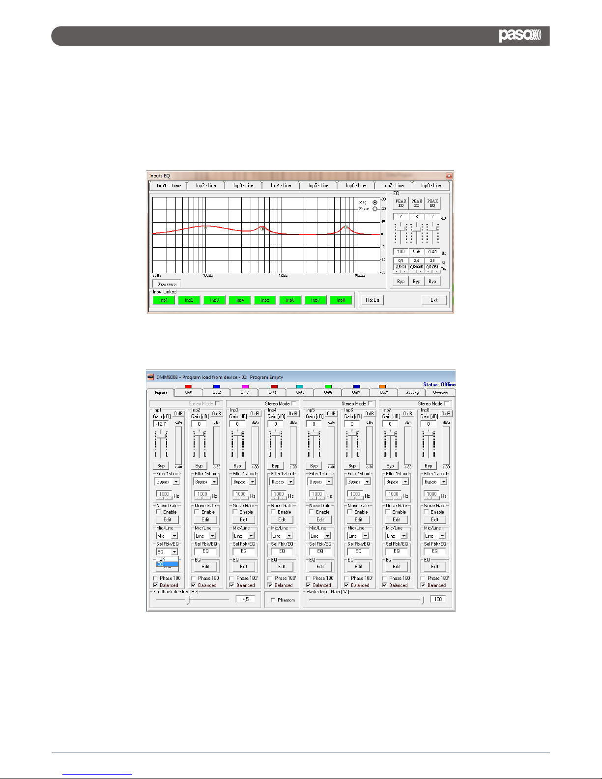
Once the all 3 available cursor are shown on the Frequency Response graphic, just selecting anyone of them
with the mouse's arrow and maintaining the mouse's click pressed, it is possible to move and place the
selected cursor on the desired frequency and with the desired gain.
For setting the filter's Q, still need to enter the desired value directly in the dedicated box in the filters' editing
main sub-frame.
In order to see what's the “Phase” response of the channel once set up the all filters of the EQ, it is possible,
selecting the Phase choice on the top right of the Graphic window, to turn the graphic in “Phase Response
Graphic”:
When the Microphone Source is selected, on the related channel is possible to adjust the Input level from -
127dB up to 12dB.
When selected microphone as input, the user can chose to select on the input itself a 3bands Eq process on the
Input signal, or a Feedback Eliminator.
When the 3 bands Eq is selected, the Equalizer can be edited in the same way shown for the Line Input case.
18
DMX 8008
Page 21
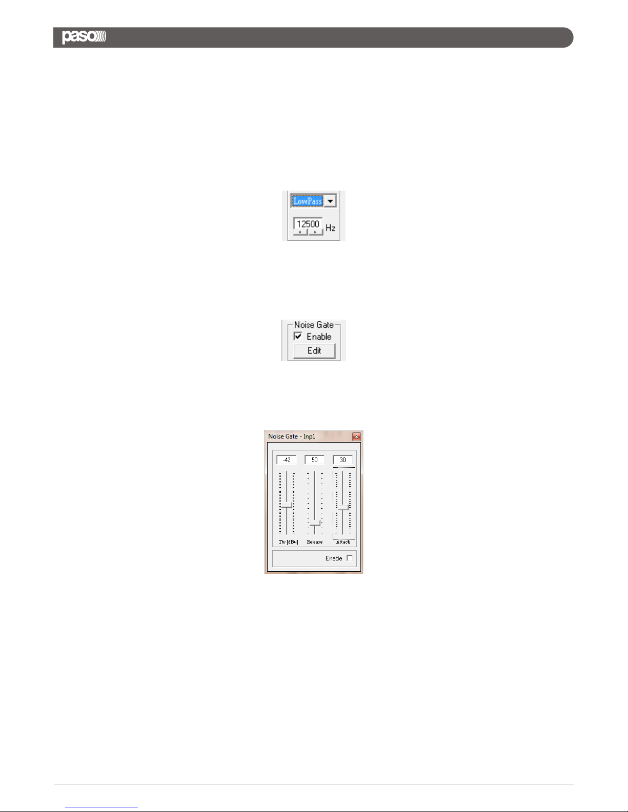
When the Feedback Eliminator is selected, it can be activated or not, and when active, its deviation can be set.
The Feedback Eliminator is working on the base of a frequency shift process avoiding the feedback to raise up.
The speed of the feedback elimination process it is just defining the amount of frequency shift is added to the
input signal.
Independently from the Input selected (microphone or line), on the Inputs are ever available a first order Low
Pass filter and a Noise Gate.
First Order Low Pass Filter: this filter is a first order Low Pas, with a 3dB/Oct Slope.
The filter's cut of frequency is ranging from 20kHz up to 1kHz by steps of 1/3 of Octave.
The filter can be made active or not (bypassed), checking or unchecking the “Enable” check box:
Once active, the smooth first order LP filter is intended to be mainly used with the microphone's input selected,
in order to reduce the amount of high frequencies without affecting significantly the voice quality, nevertheless
increasing the immunity to the Feedback.
Noise Gate: the particular DMX8008 Noise Gate can be selected or bypassed checking or unchecking the
“Enable” check box:
This Noise Gate has been thought as Noise Gate for the Line inputs, but also as Auto Switch On/Off when
operating with the microphone inputs.
From this point of view, the range of a standard Noise gate have been extended, and particularly the one of the
Gating Threshold, so to better fit the characteristics of the voice signal
Gating Threshold: the gating threshold is ranging from -80dB up to 0dBu.
This threshold is allowing to set a gating level for the microphones, pretty high, allowing in this way to open or
close at level far from the common noise floor, so to open or close when a hi level signal, as the voice, is
detected at the microphone's input or not.
Attack Time: it is ranging from 1ms up to 1 second and represent the speed of the Noise Gate in “closing” the
input level once a signal in input is detected to be below the Gating Threshold.
Release Time: t is ranging from 10ms up to 1 second and represent the speed of the Noise Gate in “opening”
the input level once a signal in input is detected to be above the Gating Threshold.
19
DMX 8008
Page 22
A Phantom power supply can be activated if microphones using a such power supply are chosen.
Note: at the bottom of the Meter Bar aside the level slider, both when Line or Microphone Input are selected,
there is an indicator indicating in real time and precisely what's the current Input signal level in dBu
Note1: a “Balance” check box is also available.
When a Balanced Input is used, it has to be checked, so to get the proper input level adjustment.
If a Not Balanced Input is used, the box has to be left unchecked and the input level is automatically adjusted
at +6dBu.
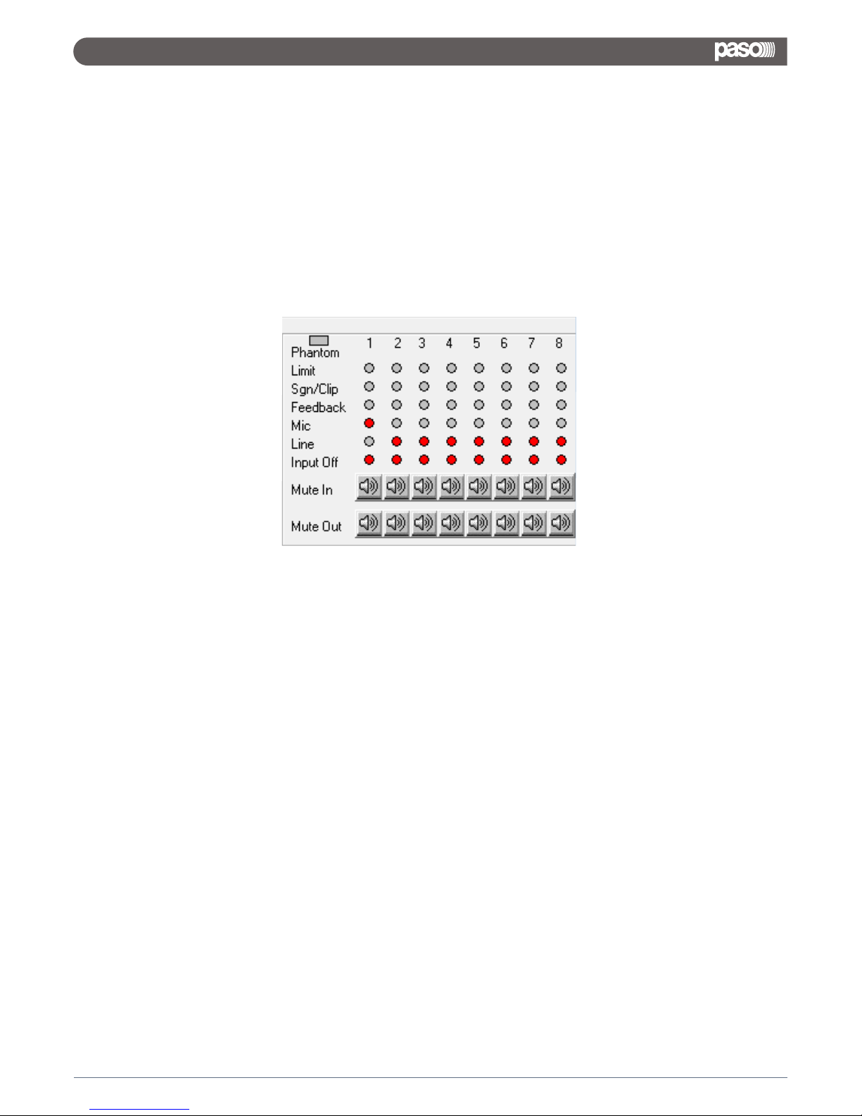
Note2: In order to help tuning properly the Noise Gate when used as Microphone Input On/Off Switch, 8 Leds
indicating the Inputs status is available in the Led meters interface:
The line of “Input Off” leds is indicating when an Input is Off or Muted by the Noise Gate.
In that case the related Led is turned RED.
Once set the microphone inputs configurations, if used the Noise Gate as microphone On/Off Switch, the Noise
Gate parameters and mainly the Gating Threshold can be tuned checking when the corresponding Input will be
muted without any direct source in input but the noise floor.
20
DMX 8008
Page 23
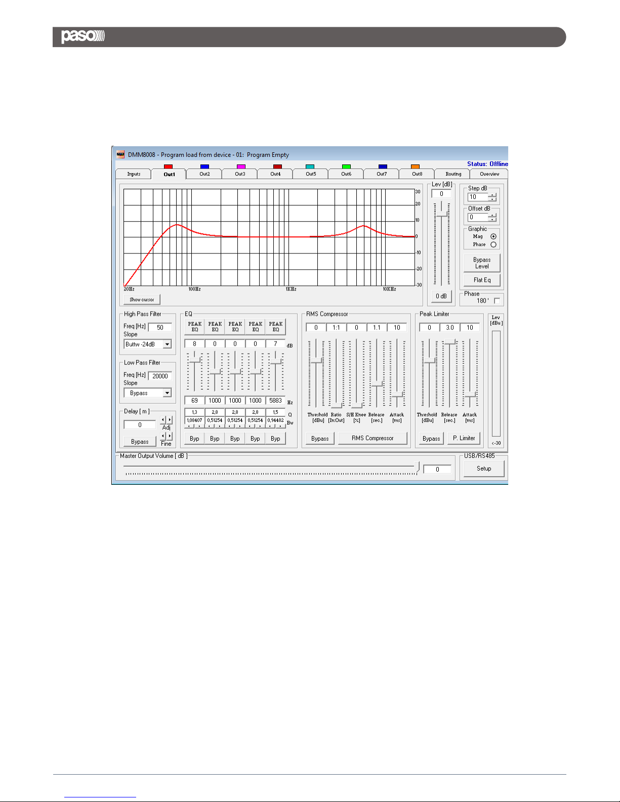
From this windows is possible to access and edit the most significant signal processes of the 8 output channels.
High Pass Filter: from this sub-frame it is possible to set the Output Channels High Pass Filter (HPF).
“Frequency”: (Low Cut frequency) the selectable frequencies range is from 20Hz to 20kHz in steps of 1/24 of
an Octave.
“Slope”: allows you to select the X-Over's High Pass Filter Shape and Order.
The available shapes and orders for the High Pass Filter are listed below:
– Bypass (High Pass Filter Bypassed)
– Buttw 6dB (Butterworth Filter 6dB/Oct Slope)
– Buttw 12dB (Butterworth Filter 12dB/Oct Slope)
– LRiley 12dB (Linkwitz/Riley Filter 12dB/Oct Slope)
– Bessel 12dB (Bessel Filter 12dB/Oct Slope)
– Buttw 18dB (Butterworth Filter 18dB/Oct Slope)
– Buttw 24dB (Butterworth Filter 24dB/Oct Slope)
– LRiley 24dB (Linkwitz/Riley Filter 24dB/Oct Slope)
– Bessel 24dB (Bessel Filter 24dB/Oct Slope)
3.2 OUTPUTS PAGE
21
DMX 8008
Page 24

Low Pass Filter: from this sub-frame it is possible to set the Output Channels Low Pass Filter (LPF).
“Frequency”: (High Cut frequency) the selectable frequencies range is from 20Hz to 20kHz in steps of 1/24 of
an Octave.
“Slope”: allows you to select the X-Over's Low Pass Filter Shape and Order.
The available shapes and orders for the Low Pass Filter are listed below:
– Bypass (High Pass Filter Bypassed)
– Buttw 6dB (Butterworth Filter 6dB/Oct Slope)
– Buttw 12dB (Butterworth Filter 12dB/Oct Slope)
– LRiley 12dB (Linkwitz/Riley Filter 12dB/Oct Slope)
– Bessel 12dB (Bessel Filter 12dB/Oct Slope)
– Buttw 18dB (Butterworth Filter 18dB/Oct Slope)
– Buttw 24dB (Butterworth Filter 24dB/Oct Slope)
– LRiley 24dB (Linkwitz/Riley Filter 24dB/Oct Slope)
– Bessel 24dB (Bessel Filter 24dB/Oct Slope)
EQ: from this sub-frame it is possible to set the Output Channels five available Peaker (Bell) or variable Q
Shelving Filters.
The DMX8008 allows the user to select either Bell or variable Q Shelving Parameters and assign them
independently using the 5 available filters.
The selection can be done just pressing the “Peak Eq” button on top of the filters' gain sliders and selecting one
of the 3 available filters' type: Peaker, variable Q high Shelving and variable Q low Shelving.
BELL Filter: here Center Frequency, Band Width (Q) and Gain can be adjusted.
“Center Frequency”: the selectable frequencies range is from 20Hz to 20kHz in steps of 1/24 of an Octave.
“Bandwidth BW”: the selectable BW range is from 0.0312 Octave (Q=10) up to 3.59 Octave (Q=0.4) in
steps of 0.1 Q.
“Gain”: the selectable Gain range is from -12dB to +12dB in steps of 0.5 dB.
Variable Q Low Shelving Filter: here Center Frequency, Band Width (Q) (Slope) and Gain can be adjusted.
“Center Frequency”: the selectable frequencies range is from 20Hz to 20kHz in steps of 1/24 of an Octave.
“Bandwidth BW (Slope)”: the selectable BW range is from 0.0312 Octave (Q=10) up to 3.59 Octave
(Q=0.4) in steps of 0.1 Q.
“Gain”: the selectable Gain range is from -12dB to +12dB in steps of 0.5 dB.
Variable Q High Shelving Filter: here Center Frequency, Band Width (Q) (Slope) and Gain can be adjusted.
“Center Frequency”: the selectable frequencies range is from 20Hz to 20kHz in steps of 1/24 of an Octave.
“Bandwidth BW (Slope)”: the selectable BW range is from 0.0312 Octave (Q=10) up to 3.59 Octave
(Q=0.4) in steps of 0.1 Q.
“Gain”: the selectable Gain range is from -12dB to +12dB in steps of 0.5 dB.
Note: each single filter can be independently “bypassed” for an easy setting/use of them.
To “Bypass” the single filter, just press the “Bypass” button below the filter’s parameters.
22
DMX 8008
Page 25
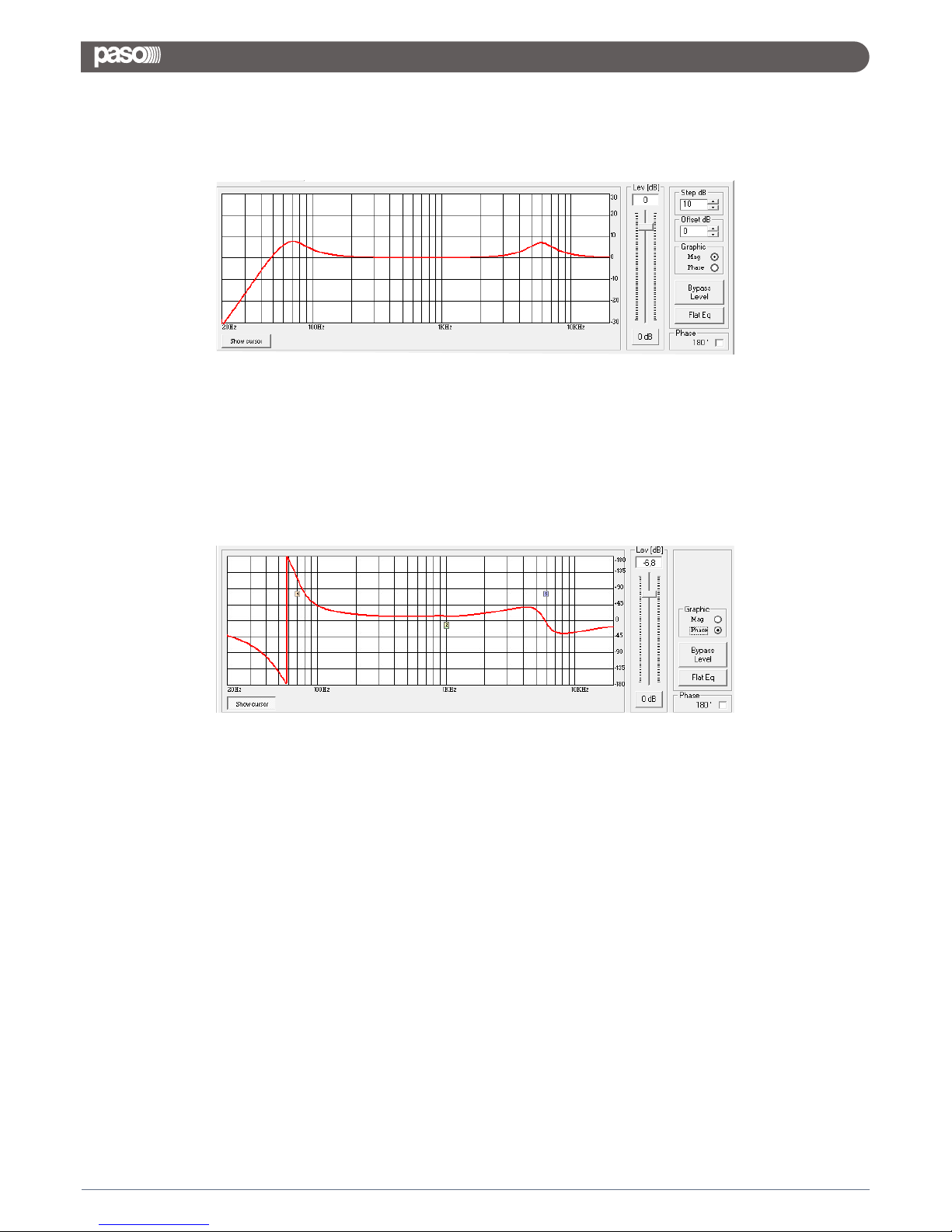
The set up of the filters and specially their frequency placement can also be done with the use of the mouse,
just activating the “Show Cursor” function, pressing the related button on the left bottom of the frequency
response Graphic.
Once the all 5 available cursor are shown on the Frequency Response graphic, just selecting anyone of them
with the mouse's arrow and maintaining the mouse's click pressed, it is possible to move and place the
selected cursor on the desired frequency and with the desired gain.
For setting the filter's Q, still need to enter the desired value directly in the dedicated box in the filters' editing
main sub-frame.
In order to see what's the “Phase” response of the channel once set up the all filters of the EQ, it is possible,
selecting the Phase choice on the top right of the Graphic window, to turn the graphic in “Phase Response
Graphic”:
Step dB – this simple function is allowing to set the resolution in dB of the Grid Lines of the Graphic displaying
the Magnitude response of the equalization.
The resolution can be set in a range from 5dB up to 50dB, by steps of 5dB.
Offset dB – here can be set an “offset” in dB in visualizing the Magnitude response of the equalization.
Once added a positive offset, more space is given in the graphic to the visualization above the 0dB, when a
negative offset is added, more space is given to the visualization below the 0dB.
The offset can be set in a range from 10dB up to -120dB, by steps of 10dB.
Level [dB] – from this sub-frame it is possible to set the Output Channels Level from -127dB up to +18dB.
Pressing the “Bypass” button at the bottom of the Level slider, the currently set level will be skipped and the
output level will be set to 0dB.
Phase – when this check box is “unchecked” the processed signal is left with its original phase.
When the check box is “checked”, then the original phase of the signal is inverted of 180Deg.
Delay – from this sub-frame it is possible to set the Output Channels Delay Time from 000.0000mS (0 meters)
up to 380.998mS (129.53932 Meters), by steps of 1mS (Adj arrows) or 20.8uS (Fine arrows).
23
DMX 8008
Page 26
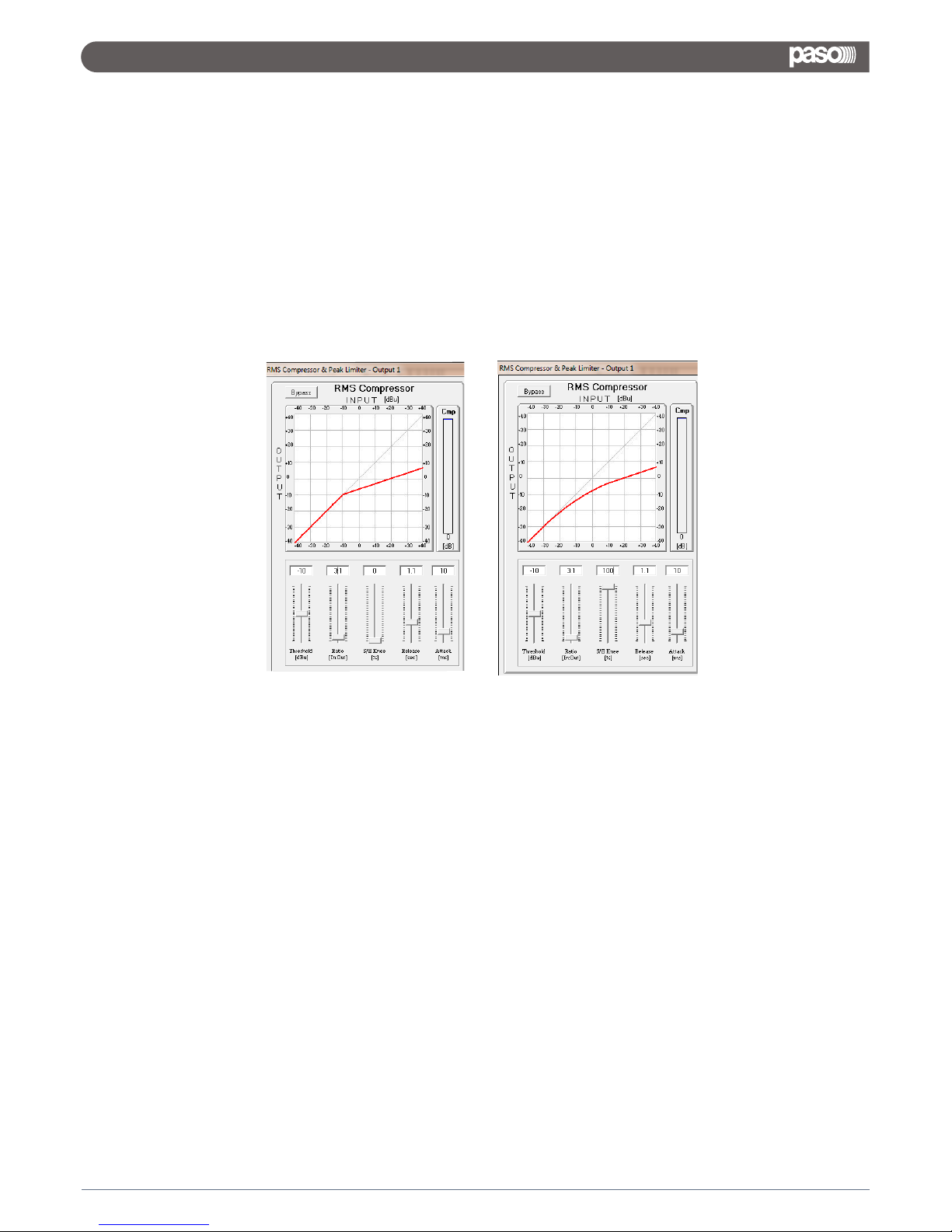
On each Output channel is available a powerful RMS compressor for improving the sound quality, followed by a
Peak limiter useful for limiting the output signal before to enter the amplification system.
Each, RMS Compressor and Peak Limiter, can be independently set.
The editable parameters can be accessed directly from the RMS Compressor and Peak Limiter subframes, or
entering a dedicated window accessible from both the sub-frames pressing the buttons “RMS Compressor” or
“P. Limiter”.
Both RMS Compressor and Peak limiter can be quickly skipped and re-activated by pressing the “Bypass”
button within the respective sub-frames.
RMS Compressor – from this sub-frame it is possible to set the Threshold, Ratio, Attack Time, Release Time
and “Knee” type of the Output Channels' RMS Compressor.
“Threshold”: the selectable range of the RMS Compressor's Threshold is from +14,2dBu (OFF) to -33,8dBu in
steps of 0.2dBu
“Ratio”: the selectable range of the RMS Compressor's Ratio is from 1:1 (Off) up to 32:1 (Lim) in steps of 1.
“Hard/Soft Knee”: the selectable range of the RMS Compressor's Knee type is from 000% (Hard) up to
100% (Soft).
“Release Time”: the selectable range of the RMS Compressor's Release Time is from 0.1s to 3s in steps of
0.1s.
“Attack Time”: the selectable range of the RMS Compressor's Attack Time is from 5ms to 200ms in steps of
1ms - from 5ms to 20ms then 5ms - from 20ms to 30ms then 10ms - from 30ms to 100ms and 20ms - from
100ms to 200ms.
Note: The RMS Compressor Threshold is defined in dBu, due to the fact that with both, Sinusoid and Squared
wave testing signals, the DMX8008 compressed output dBu (RMS) Level is the same and matching the
selected one.
24
DMX 8008
Page 27
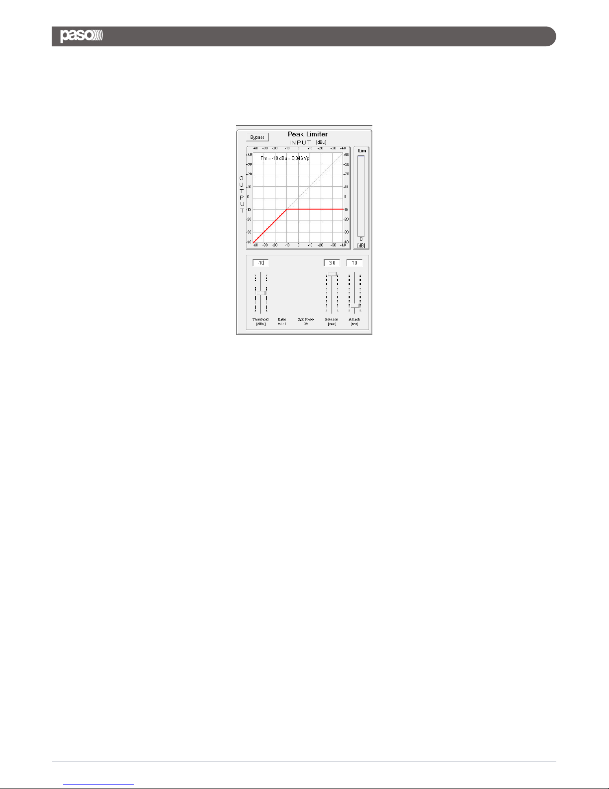
Peak Limiter – from this sub-frame it is possible to set the Threshold, Attack Time and Release Time of the
Output Channels' Peak Limiter.
“Threshold”: the selectable range of the Peak Limiter's Threshold is from +14,2dB (Limiter not active) to
-33,8dB in steps of 0.2 dB.
“Release Time”: the selectable range of the Peak Limiter's Release Time is from 0.1s to 3s in steps of 0.1s.
“Attack Time”: the selectable range of the Peak Limiter's Attack Time is from 5ms to 200ms in steps of 1ms -
from 5ms to 20ms then 5ms - from 20ms to 30ms then 10ms - from 30ms to 100ms and 20ms - from 100ms to
200ms.
Note: The Peak limiter Threshold is defined in Vp, due to the fact that with both, Sinusoid and Squared wave
testing signals, the DMX8008 Peak Limited output Vp (Peak-Peak) Level is the same and matching the selected
one.
25
DMX 8008
Page 28
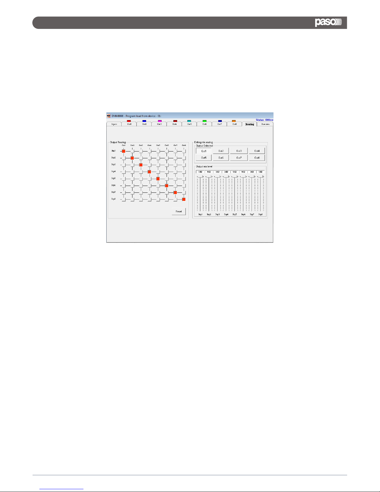
The routing Page is allowing to set the Matrix Structure of the and to assign to each Output the
desired Inputs.
On the “Output Routing” Matrix block activating the desired “node” will connect the Input and the Output
related to the Node.
On the “Editing mix routing”, it is possible to adjust the Level of each input assigned to the Output selected by
the related button.
So, selecting any one of the available 8 buttons, the related Output will be “formed” by the addition of the all
inputs (assigned by the “Output Routing” Matrix Block, with the Level percentage defined by the “Output mix
level” sliders.
The Levels of the “mixed inputs” to the selected outputs, can range from -30dB up to 0dB.
DMX8008
3.3 ROUTING PAGE
26
DMX 8008
Page 29
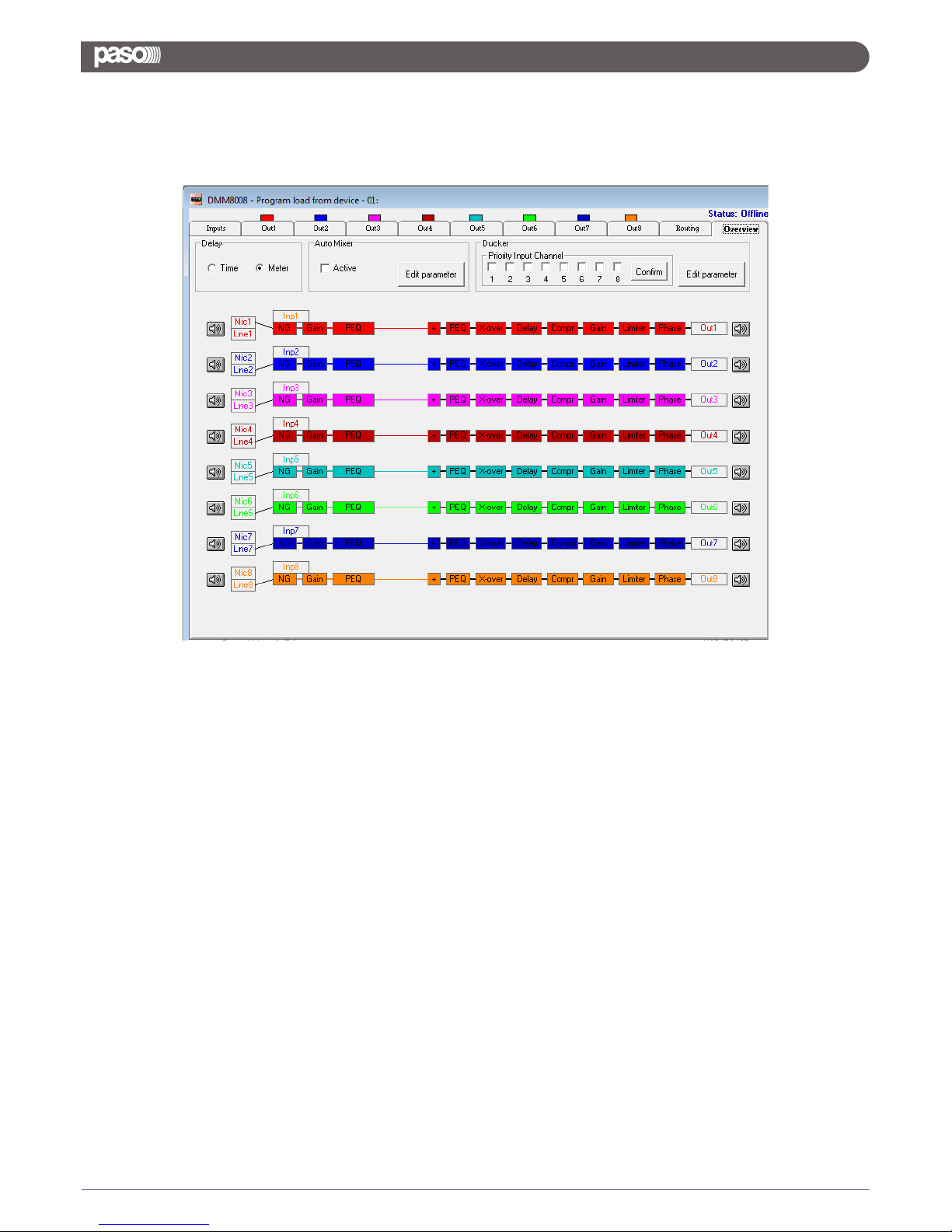
Within the Overview Page, can be checked the all channels inputs selection (between Microphone and Line), so
as any of the available processes can be accessed double clicking on its name in the processes' block diagram.
Particularly, in this page is also resumed the current selections operated for the Inputs in terms of available Eq
or Feedback Eliminator processes, when Microphone Input is selected.
Here also can be selected the “Unit” for defining the amount of delay available on each output.
The Delay can be actually set in “meters” or “milliseconds”.
In the Overview Page are also accessible the Editing Pages of the Automixer and Priority Ducker.
The DMX8008 is running 2 Classic Automixer processes, the NOM (Number of Opened Microphones) and the
Gain Sharing.
These 2 processes are used with microphones in Conference Systems for Voice quality improvement and
Feedback effect reduction.
Has to be noticed here that the DMX8008 can run together with the Classic NOM and Gain
Sharing processes, also the First order Low Pass filter and mainly the Frequency shift Feedback Eliminator.
This is providing a very strong Anti Feedback characteristic to the unit, which can let the NOM and Gain Sharing
processes act mainly in terms of Voice quality and intelligibility improvement.
The Priority Ducker is a process able to assign to up to 4 microphone/line inputs, priority on the others, which
will be attenuated in their input level as soon as a signal is detected on one of the input having the Priority.
The Priority Ducker is mainly used in Conference System applications, there where is necessary to assign a
priority to a microphone used by one Chairman or more equal priorities speakers.
Nevertheless, the Priority Ducker can be very useful also in installation systems, there where a microphone or
line input is used as Priority channel for priority or urgent announcements.
3.4 OVERVIEW PAGE
27
DMX 8008
Page 30

The DMX8008 can perform 2 Classic processes of the Automixers, the NOM Attenuation and the Gain Sharing
one.
NOM Attenuation : this is a process able to detect the number of microphones active (Opened) at the same
time and, on the base of the Number of Opened Microphones, it is applying a predefined amount of attenuation
to each microphone's input.
A simple formula determines the NOM Attenuation: “Attenuate by 3dB for every doubling of the Number of
Open Microphones”, which translates to the following:
NOM Attenuation = 10log(NOM)
Here are some examples to better illustrate the NOM attenuation:
•1 active microphone means no attenuation: 10log(1) = 0dB
•2 active microphones translates to doubling the NOM: 10log(2) = 3dB of attenuation
Once the limit of 8 active microphones is reached (9dB attenuation), the NOM count and attenuation
maximum is reached and will not increase further (hopefully the eight people trying to talk at once will have
figured that out by then…).
Here following a table resuming the NOM Attenuation applied on the the base of the number of Opened
Microphones:
NOM
Output Gain Adjustment (dB)
10log (NOM)
1
2
3
4
5
10
20
100
0
-3.0
-4.8
-6.0
-7.0
-10.0
-13.0
-20.0
3.5 AUTOMIXER FUNCTIONS
Note: The NOM attenuation could be free confidurable.
28
DMX 8008
Page 31
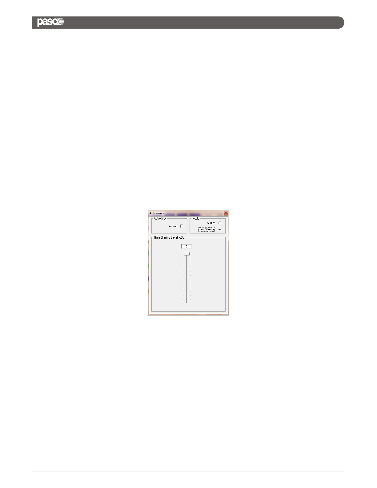
Gain Sharing: This process is based on a dynamic control of the gain of each microphone channel; the gain of
each channel is adjusted by comparing its level to the level of the sum of the level of the all microphones.
The gain is computed so that the combined system gain of all microphones remains constant.
In this way, the microphones with the strongest signal are given the highest gain and those with low level
signals have their gain reduced.
Specifically, each microphone channel is attenuated (turned down) by the amount, in dB, equal to the
difference between that microphone channel’s level and the sum of all microphone channel levels.
In example, if two talkers are each speaking on their own microphone channel at the same level, then the level
of the sum of all channels would be 3 dB higher than the level from each of these mics (power addition).
Each microphone would then be turned down 3 dB.
If a person is being picked up equally by two microphones, the sum of these two signals would increase 6 dB.
(The 6 dB increase results from the addition of two coherent signals.)
The level in each mic channel would be 6 dB lower than the sum and the gain of each mic is reduced 6 dB.
The resulting output would be the same as if only one mic were on. In a final example, a talker is speaking into
his mic, but his voice also enters an adjacent microphone at a level 4 dB lower.
In a gated system, this second mic could very easily be gated “on” creating comb filtering effects.
In the gain sharing system, the gain of the second mic will be attenuated 4 dB.
This makes the level from the second mic 8 dB lower than the first, which will greatly reduce the interference.
As said , the DMX8008 can perform both processes.
The user can select which one to make active, entering the Automixer editing page and selecting the desired
process, checking the related check box.
If selected the Gain Sharing option, the Max Gain available to the SUM of the all microphones can even be set
using the Gain Sharing level Slider.
When the Slider is set on 0dB, the MAX output available (virtually 0dB) is available to the SUM of the all
microphones level.
If the slider is set at a different value, as in example -6dB, the Max gain allowed to the SUM of the all
microphones level is -6dB.
This means that respect the case of the slider set to 0dB, the Gain of the microphones will start to be adjusted
6dB earlier when the slider is set to -6dB.
29
DMX 8008
Page 32
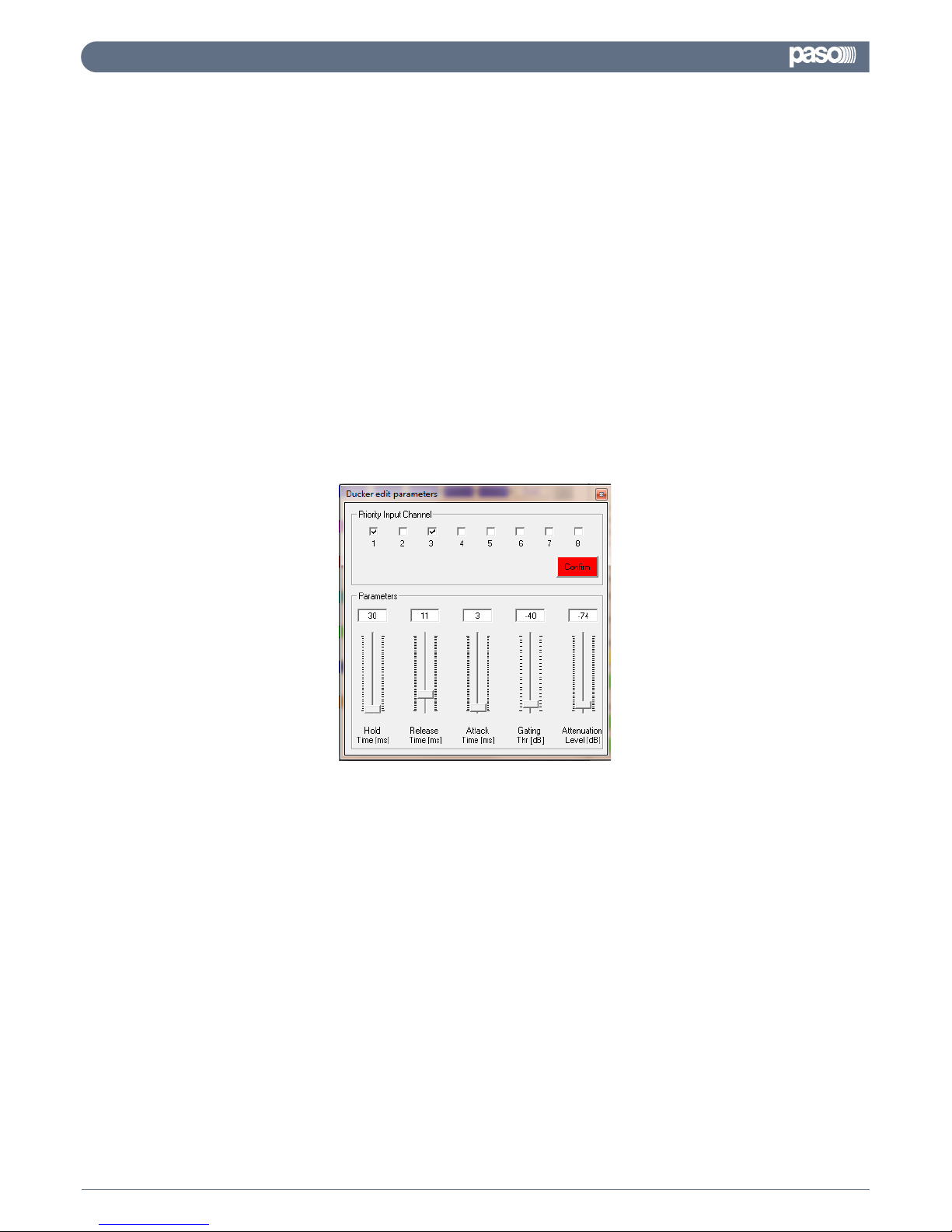
The Priority Ducker is a Side-Chain dynamic process, used to attenuate the level of a certain number of input
channels on the base of a signal detected on an independent input.
In our case, the Priority Ducker Process is allowing to select from 1 to 4 Inputs as inputs having priority on the
other ones.
When signal above a defined threshold is detected on one of the Priority Inputs, the all others are attenuated of
a defined amount of dB.
The Priority Ducker implemented on the DMX8008 is allowing to assign to up to 4 of the all available
Microphone/Line Inputs, Priority on the others.
Particularly, when a signal above the Gating threshold is detected on one of the Priority Inputs, the other inputs
are attenuated of the Attenuation Level.
The Attenuation action is taken with the Attack Time speed and is maintained for the Hold time, after the signal
on the Priority channels dropped below the Gating Threshold, before to go back to the original level in a time
defined by the release time.
The all parameters of the DMX8008 Ducker, can be set within the Ducker Edit Parameters window
Here can be defined the following
Priority Input Channel: up to 4 check boxes can be checked for choosing up to 4 channels which will have
priority on the unchecked ones.
Once selected the Priority Channels, in order to make the Priority effective, need to confirm the selection
pressing the “Confirm” button.
Gating Threshold: it is the threshold defining the limit has to be passed by the input signal level on the
Priority channels to activate the ducking process and it is ranging from -44dB up to 0dB.
Attenuation Level: it is amount of attenuation applied to the channels not having priority when the Ducking
process is active and is ranging from 0dB up to -80dB.
Attack Time: it is the speed needed by the Ducking process to reach the set Attenuation Level once the
Ducking process is activated and is ranging from 1ms up to 2 seconds.
Hold Time: it is the time in between the de-activation of the Ducking process and the Release action and is
ranging from 10ms up to 1 second
Release Time: it is the speed needed by the Ducking process to get back to the original gain level of the
channels not having Priority, once the Ducking process is de-activated and is ranging from 1ms up to 2
seconds.
3.6 PRIORITY DUCKER
30
DMX 8008
Page 33
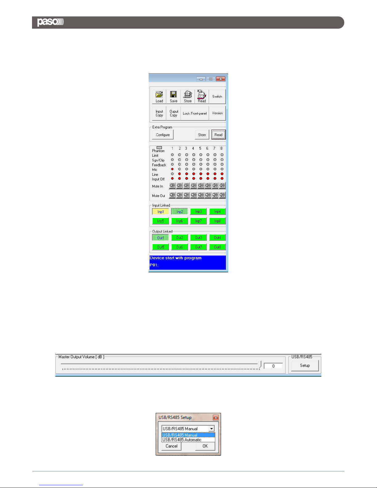
In this background screen, ever present together with the other editing pages, is displayed the channels'
status.
Here are mainly reported the all activities of the DMX8008 front panel's leds.
Each Input/Output channel can be muted so as input channels and output channels can be “linked” together so
to report on the all linked channels the same parameters adjustments.
To link 2 or more channels, it is enough to press the related buttons within the “Input Linked” and “Output
Linked” frames.
The Main output Level can also be adjusted from this Utilities window.
This is the same Level control used by the Wall Panel Remote Control.
Through the “Setup” button a selection window can be accessed allowing to set the DMX8008 in Manual Mode,
choosing the USB or RS485 interface, or in Automatic mode.
3.7 BACKGROUND UTILITIES
31
DMX 8008
Page 34
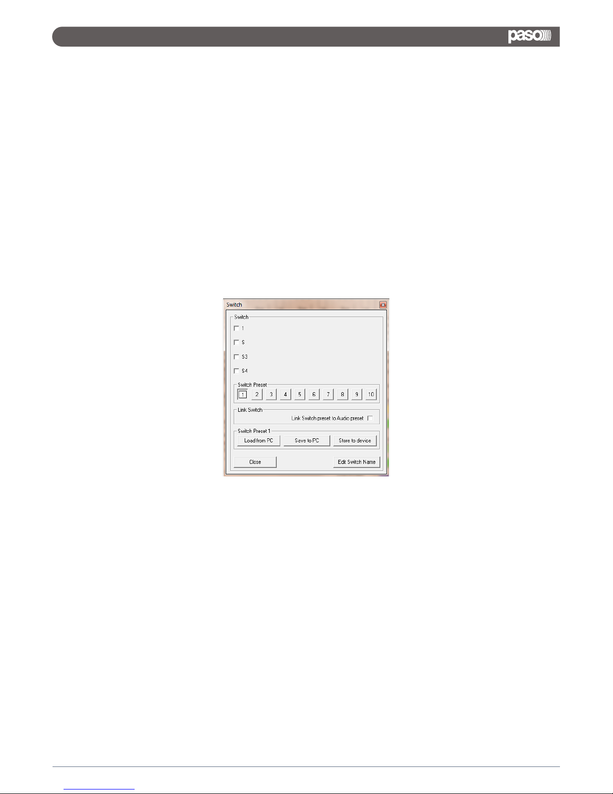
From the Utilities Window, can be accessed also the all processes for Saving/Recalling presets to/from Pc and
to/From the DMX8008 and for configuring Special Processes activated by the External Switch Input Ports.
Particularly:
Load: allows to load on the Pc Remote Control a configuration previously saved on Pc
Save: allows to save on Pc the current editing session
Store: allows to store on the DMX8008, in one of the 6 available location, the current editing session
Read: allows to read from the DMX8008, one of the 6 stored presets and to display it on the current editing
session
Input Copy: allows to copy the setting of one Input channel on an other one
Output Copy: allows to copy the setting of one Output channel on an other one
Switch: this particular button is allowing to enter e window where from up 4 lines (switches) can
be set as 0 (boxes unchecked) or 5V (boxes checked).
The switches controlled by this window actually set as 0V or 5V the physical 4 output “switch” lines available on
the DMX8008 back panel and useful for controlling remote devices.
From this editing window, up to 10 different presets can be created, where a specific Switches configuration is
assigned.
In order to create the presets, need first to press one of the 10 “Switch Preset” buttons
Once the specific button is presses, to that button will be assigned the current status of the 4 S1/S2/S3/S4
switches.
To any button, a different S(x) configuration can be assigned.
The different configuration will be maintained until the Pc Sw is open.
On the Pc can be saved ONLY a Configuration a time, the Pc will not store the configurations of the 10 buttons.
Therefore, on Pc will be saved any time the current configuration of the Switches S1/S2/S3/S4.
The several configurations can be then recalled and they'll be assigned to the currently pressed “Switch
Preset” button.
32
DMX 8008
Page 35
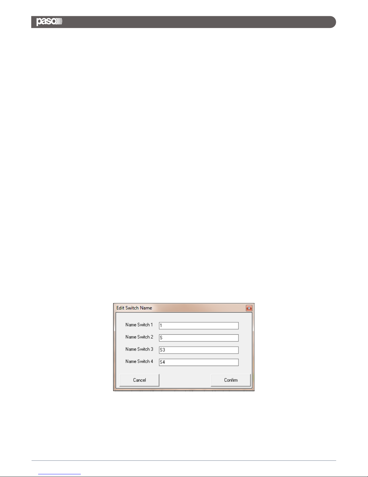
In example, creating the following configuration
S1 = checked
S2 = unchecked
S3 = unchecked
S4 = unchecked
The configuration can be saved on Pc as “S1_On”.
If recalled, when the Switch Preset button ONE is pressed, then to the Switch Preset Button 1 will be associated
the above configuration of the switches.
Different S(x) configurations can be saved with different names and be associated to different Switch Preset
buttons.
Once assigned different S(x) configurations to different Switch Preset buttons, the user can recall the several
configurations from Pc Sw just pressing the several Switch Preset buttons.
In order to store the 10 Preset configurations within the DMX8008, so to be able to recall them by DMX8008
front panel or together with the “Audio Presets” if active the “link” function (see later), it is enough to press any
Switch Preset button in order to make it active and press the “Store to Device” button.
The preset related to the currently active Switch Preset button, will be stored in the equivalent preset location
within the DMX8008.
In order to store the all 10 presets, need to make active one by one the all Switch Preset buttons and for
anyone of them press the “Store to Device” button.
Once stored within the DMX8008, the 10 presets controlling the S(x) switches status can be recalled manually
and independently from the “Audio” Presets, from the unit's front panel.
If the User want to recall the Switch Presets together with the Audio Presets, which would mean that together
with the Audio preset number 1, the user want to be recalled also the Switch Preset number 1 (the Audio preset
and Switch Preset numbers have to match...), then is necessary to LINK the Audio Presets and the Switch
Presets.
This can be done checking the “Link Switch preset to Audio preset” check box within the Link Switch frame of
the Switch Editing window.
To the Switches can also be assigned a NAME, just pressing the “Edit Switch Name” button and entering the
Edit Switch Name window
33
DMX 8008
Page 36
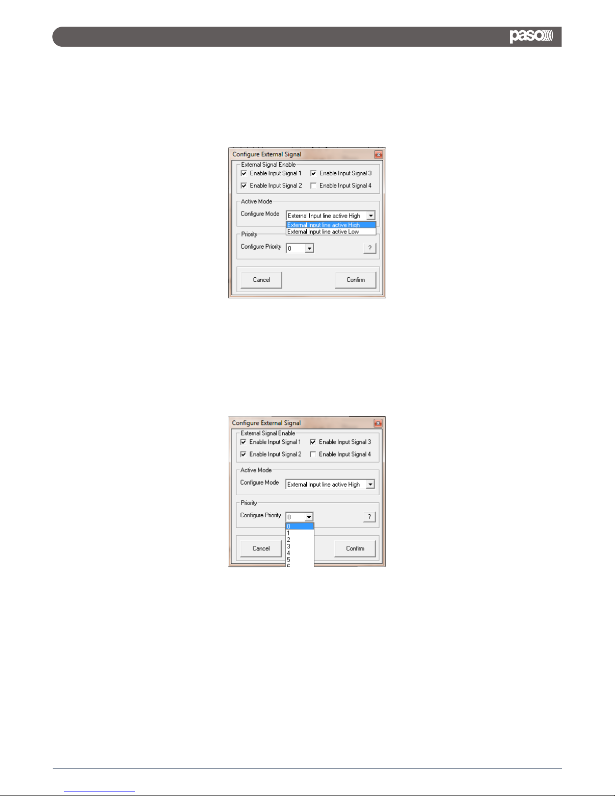
Extra Program: the External Program section is allowing the user to set as active or not active anyone of the 4
available Input Switches.
When set as active one or more of them, it is also possible to define with the “Configure Mode” option, if the
Input Switch signal has to be considered active on its High or Low level detected.
Furthermore, it is also possible, in case more Events related to the Input Switches are occurring at the same
time, so activating at the same time more than one Switch, to assign a Priority in “serving” the events related
to the active Switches (see below).
34
DMX 8008
Page 37
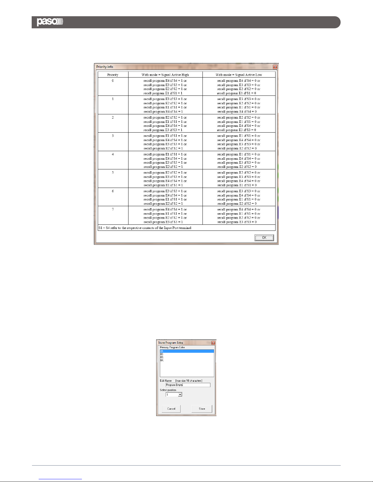
The desired Priority can be set selecting one of the 8 options available, corresponding to the following Priority
Table (accessible pressing the “?” button aside the “Configure Priority” selection box):
Once operated the all desired selections, need to “Confirm” them before to exit the “Configure External Signal”
Page.
To anyone of the 4 External Switches (Events) can be related a specific process.
This process is corresponding to a Input/Output specific Configuration (Preset), that has to be recalled ONLY if
the related Event (Switch Active) is occurring.
So, 4 Extra Presets other than the 6 available for the normal operations, can be created and stored, so to be
recalled ONLY when the related event is occurring.
Once create the 4 Extra Presets, they can be stored within the DMX8008 Through the Button “Store”:
35
DMX 8008
Page 38
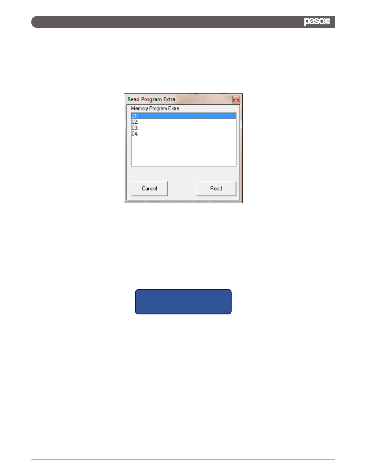
The Extra Presets can be saved in 4 available locations where the location number is corresponding to the
related Switch Input Event.
To anyone of the 4 Extra Preset can be assigned a specific name.
Once saved the Extra Presets, they can be anytime recalled for check using the “Read” button.
For Leaving the Remote control Sw, it is enough to click “Exit” on the “file” option on the top left corner of the
Main Editing Environment.
Once left the Pc Sw Remote Control, the DMX8008 will go back to the Stand Alone Mode and the LCD will
display the currently running preset:
36
DMX 8008
DMX8008
01: Current Preset Name
Page 39

8 electronically balanced ( Mic - Line - Unbalanced )
8 electronically balanced
Line: +14dBu; Mic: -20/0dBu ( +6dBu unbalanced )
35dB ( 23dB analog, 12dB digital )
+14dBu
0.005% at 1kHz 0dBu
>104dBA
20Hz-20kHz +/-1dB
4 x AK5385B 24bit, 1 x Ak4358 24bit (48kHz)
48Vdc
Dream SAM3716, 24bit (data) x 96bit (coeff.)
24 x 32 bit for filtering process; 96bits resolution on intermediate
computation results
3-band parametric selected as peaking or Low/High shelving with
variable Q per input channel
Low/High pass 1st order filter per input channel
5-band parametric EQ selected as peaking or Low/High shelving with
variable Q per output channel
From -12dBu up to +12dBu by 0.5dBu resolution steps
Selectable with a 1/24th of octave resolution step from 20Hz up to 20kHz
Q from 0.4 up to 10 by 0.1 resolution steps
Butterworth 6/12/18/24dB per octave
Bussel, Linkwitz-Riley and custom 12/24dB per octave
Filter resolution 1/24th of octave
Threshold from 14dBu up to -34dBu
Attack time from 5ms up to 200ms (1ms resolution up to 20ms, 10ms
resolution up to 100ms and 20ms resolution up to 200ms)
Release time from 0.1 sec up to 3 sec (0.1 sec resolution)
Ratio from 1:1 to 32:1 (compressor only)
Adjustable soft or hard knee (compressor only)
380,998 ms 21 us increment/decrement steps per output channel only
Pitch shifting algorithm only for Mic input channels
NOM attenuation, Gain sharing algorithm and priority ducking processing
6 user presets + 4 by using S1-S4 digital input ports
2 x 24 character LCD display with white/blue LED backlight
6-LED status indicators (Line, Mic, Mute I/O, Signal, Clip,Limiter)
1-LED indicator Phantom power
6 x front push button (Preset recall, Setup)
USB type B connector
2 x 12 pin Phoenix connector (Mic/Line inputs)
2 x 12 pin Phoenix connector (Line outputs)
2 x 4 pin Phoenix connector (S1-S4 digital input ports - TTL level 0-5V)
2 x 4 pin Phoenix connector (S1-S4 digital output ports - TTL level 0-5V)
2 x RJ45 for RS485 In/Out connection
1 x RJ45 with activity leds for Ethernet connection (10/100 TCP-IP)
IEC C13 16A connector; power on/off switch
FBT WP8008 wall panel control
PC users interface; Free app. for iPad®
90-240Vac (50/60Hz) - 40W
19" x 1.75" x 9" ( 483 x 44 x 229mm ) - 1RU
7.71lbs (3.5kg) / 8.82lbs (4kg)
4. TECHNICAL SPECIFICATIONS
Analog Input
Analog Output
Maximum Input Level
Mic Input Gain
Maximum Output Level
THD+N
S/N
Frequency Response
AD & DA Converters
Phantom Power
DSP Engine
DSP Resolution
Input Equalization
Output Equalization
Filter Gain
Center Frequency
Filter Q/BW
Crossover Section HPF/LPF
RMS Compressor and Peak Limiter
Delay
Feedback Eliminator
Automixing Functions
Device Presets
Front Panel
Rear Panel
Optional Device
Included Software
Main AC
Dimensions
Weight, Net/Shipping
Audio
General
Specifications subject to change without notice.
DSP & Processing
Impedance Line Mic Input 3300 Ohm / Outputs 115 Ohm
DMX 8008
Page 40
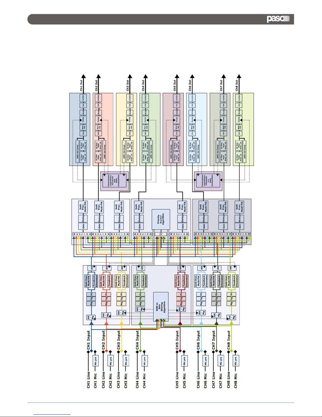
DMX8008 Pro Digital Matrix 8 in x 8 out with «Feedback Elim OR EQ, Auto mix and Priority Ducker»
5. BLOCK SCHEME
38
DMX 8008
Page 41

U.A.R.T. SETTING
BAUD-RATE = 57600
PARITY = NONE
DATA BIT = 8
BIT STOP = 1
TCP/IP SETTING
REMOTE_PORT = 1001
IP ADDRESS = from 1. 0. 0. 1 to 223.255.255.254 with:
- IP=1.0.0.2 to IP=126.255.255.254 automatically SUBNET MASK= 255. 0. 0. 0
- IP=127.0.0.2 to IP=191.255.255.254 automatically SUBNET MASK= 255. 255. 0. 0
- IP=192.0.0.2 to IP=223.255.255.254 automatically SUBNET MASK= 255. 255. 255. 0
GATEWAY = IP(0). IP(1). IP(2). 1
FRAME PROTOCOL
The REMOTE CONTROL must be send to the DEVICE the following frame:
TX:
STX ID_M ID_N CMD D0 D1 D2 D3 D4 D5 D6 D7 ETX
Where:
STX = F0H Start message
ID_M = 46H Id device
ID_N = 0,..,64 Id number device (0 only for USB / TCP/IP connection; 1,..,64 for RS485)
CMD = xx Command type
DATA0,..,7= xx Data byte
ETX = F7H End message
When the DEVICE receive this frame it evaluate the command type and after the execution it resend to
the REMOTE CONTROLL an acknowledge, This acknowledge is dependent on the command type
6. COMMUNICATION PROTOCOL
39
DMX 8008
Page 42
COMMAND TYPE
CONNECTION REQUEST 00H
UPDATE GAINS-PHASE-MUTE 01H
UPDATE ROUTING 08H
CLOSE SINGLE DEVICE 0FH
UPG_MASTERGAIN_CMD 16H
SWITCH_S_CMD 1AH
RECALL_PRESET 1BH
CMD_UPG_BALANCED 1FH
INC_DECR_GAIN_LINKED_CMD 2FH
INC_DECR_GAIN_CMD 30H
INC_DECR_MASTERGAIN_CMD 31H
INC_DECR_MASTERVOLUME_CMD 32H
MUTE_UNMUTE_CMD 33H
UPG_ONLY_GAINS_CMD 34H
CHANGE_PRESET_SWITCH_CMD 3DH
LINK_SWITCH_CMD 3EH
UPG_AUTOMIX_BYP_CMD 61H
UPG_AUTOMIX_MODE_CMD 62H
UPG_AUTOMIX_GS_CMD 64H
READ_AUTOMIX_NOM_ATT_CMD 0EH
UPG_DUCKER_PRIORITY_CMD 66H
UPG_DUCKER_HOLD_CMD 67H
UPG_DUCKER_REL_ATK_CMD 68H
UPG_DUCKER_THR_CMD 69H
VUMETER_OUT_CMD 36H
VUMETER_LIM_CMD 37H
VUMETER_CMP_CMD 38H
READ_VERSION_CMD 39H
CLOSE ALL DEVICES 8FH
READ_MAC_ADDRESS_CMD B2H
VUMETER_IN_CMD 55H
COMMUNICATION BETWEEN DEVICE AND REMOTE CONTROL
READ_VERSION_CMD: CMD=39H
TX:
RX:
The SyncMos version is V1.0 so the user can read Sm0 = 0, Sm1 = 1, Sm2 = 0
The current STM8S version is V1.0.2 so the user can read ST0 = 1, ST1 = 0, ST2 = 2
Type: type of the device,Type=1 then the device is DMM8008
STX ID_M ID_N CMD D0 D1 D2 D3 D4 D5 D6 D7 ETX
F0H 46H XX 39H 00H 00H 00H 00H 00H 00H 00H 00H F7H
F0H 46H XX 39H Sm0 Sm1 Sm2 St0 St1 St2 46H Type F7H
STX ID_M ID_N CMD D0 D1 D2 D3 D4 D5 D6 D7 ETX
40
DMX 8008
Page 43
CONNECTION REQUEST: CMD=00H
(to lock the hardware interface when the PC is connected)
TX:
RX:
If the device is connect and the ID_N is correct then the device resend the same frame but with the
D0=46H and the hw interface is locked
UPDATE GAINS-PHASE-MUTE: CMD=01H
TX:
Chn=0,...,15: Channel selected, 0,..7=In1,..,In8; 8,...,15=Out1,..,Out8
if Chn=0,..,7 then Input channel
BypG= Input Bypass Gain = 8 bit where LSB=Input1,..., MSB=Input8; Value=0,1 where 0=not
bypass, 1=bypass
Mute= Input Mute = 8 bit where LSB=Input1,..., MSB=Input8; Value=0,1 where 0=Unmute, 1=Mute
Phase= Input Phase = 8 bit where LSB=Input1,..., MSB=Input8; Value=0,1 where 0=direct, 1=invers
VolH + VolL = Value a 16Bit = 0,...,1390 (-127dB to +12dB step 0.1dB),
if Chn=8,..,15 then Output channel
BypG= Output Bypass Gain = 8 bit where LSB=Output1,..., MSB=Output8; Value=0,1 where 0=not
bypass, 1=bypass
Mute= Output Mute = 8 bit where LSB=Output1,..., MSB=Output8; Value=0,1 where 0=Unmute,
1=Mute
Phase= Output Phase = 8 bit where LSB=Output1,..., MSB=Output8; Value=0,1 where 0=direct,
1=invers
VolH+VolL= Output Gains = 16bit from 0 to 1450 (-127dB to 18dB step 0.1dB)
RX:
This is the acknowledge
UPG_ONLY_GAINS_CMD: CMD=34H
STX ID_M ID_N CMD D0 D1 D2 D3 D4 D5 D6 D7 ETX
F0H 46H XX 00H 00H 00H 00H 00H 00H 00H 00H 00H F7H
STX ID_M ID_N CMD D0 D1 D2 D3 D4 D5 D6 D7 ETX
F0H 46H XX 00H 46H 00H 00H 00H 00H 00H 00H 00H F7H
STX ID_M ID_N CMD D0 D1 D2 D3 D4 D5 D6 D7 ETX
F0H 46H XX 01H Chn 00H 00H VolL BypG Mute Phase VolH F7H
bit7 bit6 bit5 bit4 bit3 bit2 bit1 bit0
input8 input7 input6 input5 input4 input3 input2 input1
STX ID_M ID_N CMD D0 D1 D2 D3 D4 D5 D6 D7 ETX
F0H 46H XX 01H Chn 00H 00H VolL BypG Mute Phase VolH F7H
41
DMX 8008
Page 44
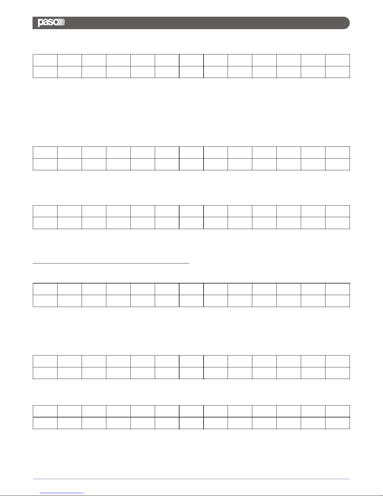
TX:
Chn=0,...,15: Channel selected, 0,..7=In1,..,In8; 8,...,15=Out1,..,Out8
if Chn=0,..,7 then Input channel
VolH + VolL = Value a 16Bit = 0,...,1390 (-127dB to +12dB step 0.1dB),
if Chn=8,..,15 then Output channel
VolH+VolL= Output Gains = 16bit from 0 to 1450 (-127dB to 18dB step 0.1dB)
RX:
This is the acknowledge
UPDATE ROUTING: CMD=08H
TX:
Chn=8,...,15: Channel selected =Out1,..,Out8;
NIn = 0,..,7 Select input to the Output channel selected 0=In1,...,7=In8
Val = 0,..,30 Input Gain from -30dB to 0dB step 1dB
if the cross InputX to OutputY is disable (mute) then Val = 80H + Val
RX:
This is the acknowledge
CLOSE SINGLE DEVICE: CMD=0FH
(to unlock the hardware interface)
TX:
RX:
STX ID_M ID_N CMD D0 D1 D2 D3 D4 D5 D6 D7 ETX
F0H 46H XX 34H Chn 00H 00H VolL 00H 00H 00H VolH F7H
STX ID_M ID_N CMD D0 D1 D2 D3 D4 D5 D6 D7 ETX
F0H 46H XX 34H Chn 00H 00H VolL 00H 00H 00H VolH F7H
STX ID_M ID_N CMD D0 D1 D2 D3 D4 D5 D6 D7 ETX
F0H 46H XX 08H Chn 00H 00H 00H 00H 00H Nin Val F7H
STX ID_M ID_N CMD D0 D1 D2 D3 D4 D5 D6 D7 ETX
F0H 46H XX 08H Chn 00H 00H 00H 00H 00H Nin Val F7H
STX ID_M ID_N CMD D0 D1 D2 D3 D4 D5 D6 D7 ETX
F0H 46H XX 0FH 00H 00H 00H 00H 00H 00H 00H 00H F7H
STX ID_M ID_N CMD D0 D1 D2 D3 D4 D5 D6 D7 ETX
F0H 46H XX 0FH 00H 00H 00H 00H 00H 00H 00H 00H F7H
42
DMX 8008
Page 45
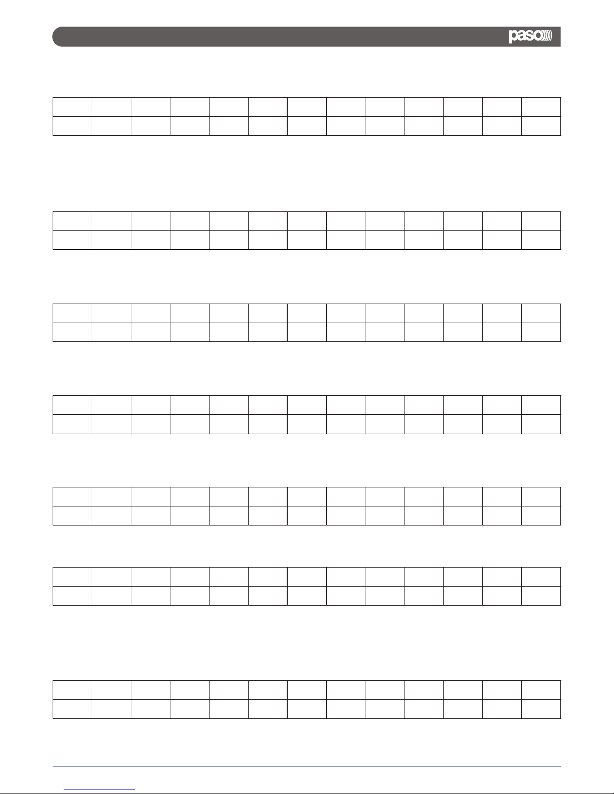
UPG_MASTERGAINS_CMD: CMD=16H
TX:
CHN=0,8: Channel selected, 0= Input, 8=Output
ValH+ValL= MasterGains = 16bit from 0 to MaxIndex
If CHN = 0 then MaxIndex = 100 (0% to 100%)
If CHN = 8 then MaxIndex = 1270 (-127dB to 0dB step 0.1dB)
RX:
This is the acknowledge
SWITCH_S_CMD: CMD=1AH
TX:
Val= 4 bit, Value of the switch set line output 0V or 5V LSB=Line1,...,LSB+3=Line4; Value=0,1
where 0=Line 0V, 1=Line 5V
RX:
This is the acknowledge
RECALL_PRESET: CMD=1BH
TX:
Npr = Recall number preset = 0,..,9
RX:
if preset selected is not empty the system load the new preset and return in D0 the value of the preset
loaded
if preset selected is empty the system skip this command and return in D0 the value = FFH
CMD_UPG_BALANCED: CMD=1FH
TX:
Chn=0,...,7: Channel selected, 0,..7=In1,..,In8;
STX ID_M ID_N CMD D0 D1 D2 D3 D4 D5 D6 D7 ETX
F0H 46H XX 16H CHN 00H 00H 00H 00H 00H ValH ValL F7H
STX ID_M ID_N CMD D0 D1 D2 D3 D4 D5 D6 D7 ETX
F0H 46H XX 16H CHN 00H 00H 00H 00H 00H ValH ValL F7H
STX ID_M ID_N CMD D0 D1 D2 D3 D4 D5 D6 D7 ETX
F0H 46H XX 1AH 00H 00H 00H 00H 00H 00H 00H Val F7H
STX ID_M ID_N CMD D0 D1 D2 D3 D4 D5 D6 D7 ETX
F0H 46H XX 1AH 00H 00H 00H VolL 00H 00H 00H Val F7H
STX ID_M ID_N CMD D0 D1 D2 D3 D4 D5 D6 D7 ETX
F0H 46H XX 1BH Npr 00H 00H 00H 00H 00H 00H 00H F7H
STX ID_M ID_N CMD D0 D1 D2 D3 D4 D5 D6 D7 ETX
F0H 46H XX 1BH Val 00H 00H 00H 00H 00H 00H 00H F7H
STX ID_M ID_N CMD D0 D1 D2 D3 D4 D5 D6 D7 ETX
F0H 46H XX 1FH Chn 00H 00H 00H 00H 00H 00H Val F7H
43
DMX 8008
Page 46
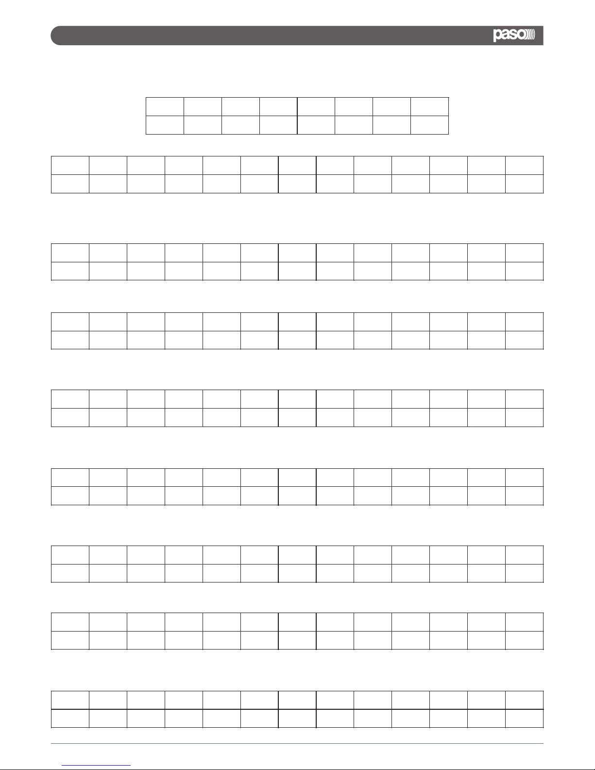
Val = Select input Balanced/Unbalanced = 8 bit where LSB=Input1,..., MSB=Input8; Value=0,1 where
0=Unbalanced, 1=Balanced
RX:
This is the acknowledge
CHANGE_PRESET_SWITCH_CMD: CMD=3DH
TX:
Val = 0,...,9 (preset1,....,preset10)
RX:
LINK_SWITCH_CMD: CMD=3EH
TX:
Val = 0,1 (0=Link OFF, 1=Link ON)
RX:
UPG_AUTOMIX_BYP_CMD: CMD=61H
TX:
ùByp= AutoMixerBypass, Value=0,1 where 0=bypass, 1=not byp
RX:
UPG_AUTOMIX_MODE_CMD: CMD=62H
TX:
bit7 bit6 bit5 bit4 bit3 bit2 bit1 bit0
input8 input7 input6 input5 input4 input3 input2 input1
STX ID_M ID_N CMD D0 D1 D2 D3 D4 D5 D6 D7 ETX
F0H
43H
XX 1FH Chn 00H 00H 00H 00H 00H 00H Val F7H
STX ID_M ID_D CMD Data0 Data1 Data2 Data3 Data4 Data5 Data6 Data7 ETX
F0H
46H
XX 3DH 00H 00H 00H 00H 00H 00H 00H Val F7H
STX ID_M ID_D CMD Data0 Data1 Data2 Data3 Data4 Data5 Data6 Data7 ETX
F0H
46H
XX 3DH 00H 00H 00H 00H 00H 00H 00H Val F7H
STX ID_M ID_D CMD Data0 Data1
Data2
Data3 Data4 Data5 Data6 Data7 ETX
F0H
46H
XX 3EH 00H 00H 00H 00H 00H 00H 00H Val F7H
STX ID_M ID_D CMD Data0 Data1
Data2
Data3 Data4 Data5 Data6 Data7 ETX
F0H
46H
XX 3EH 00H 00H 00H 00H 00H 00H 00H Val F7H
STX ID_M ID_N CMD D0 D1
D2
D3 D4 D5 D6 D7 ETX
F0H
46H
XX 61H 00H 00H 00H 00H 00H 00H 00H Byp F7H
STX ID_M ID_N CMD D0 D1
D2
D3 D4 D5 D6 D7 ETX
F0H
46H
XX 61H 00H 00H 00H 00H 00H 00H 00H Byp F7H
STX ID_M ID_N CMD D0 D1
D2
D3 D4 D5 D6 D7 ETX
F0H
46H
XX 61H 00H 00H 00H 00H 00H 00H 00H Byp F7H
44
DMX 8008
Page 47
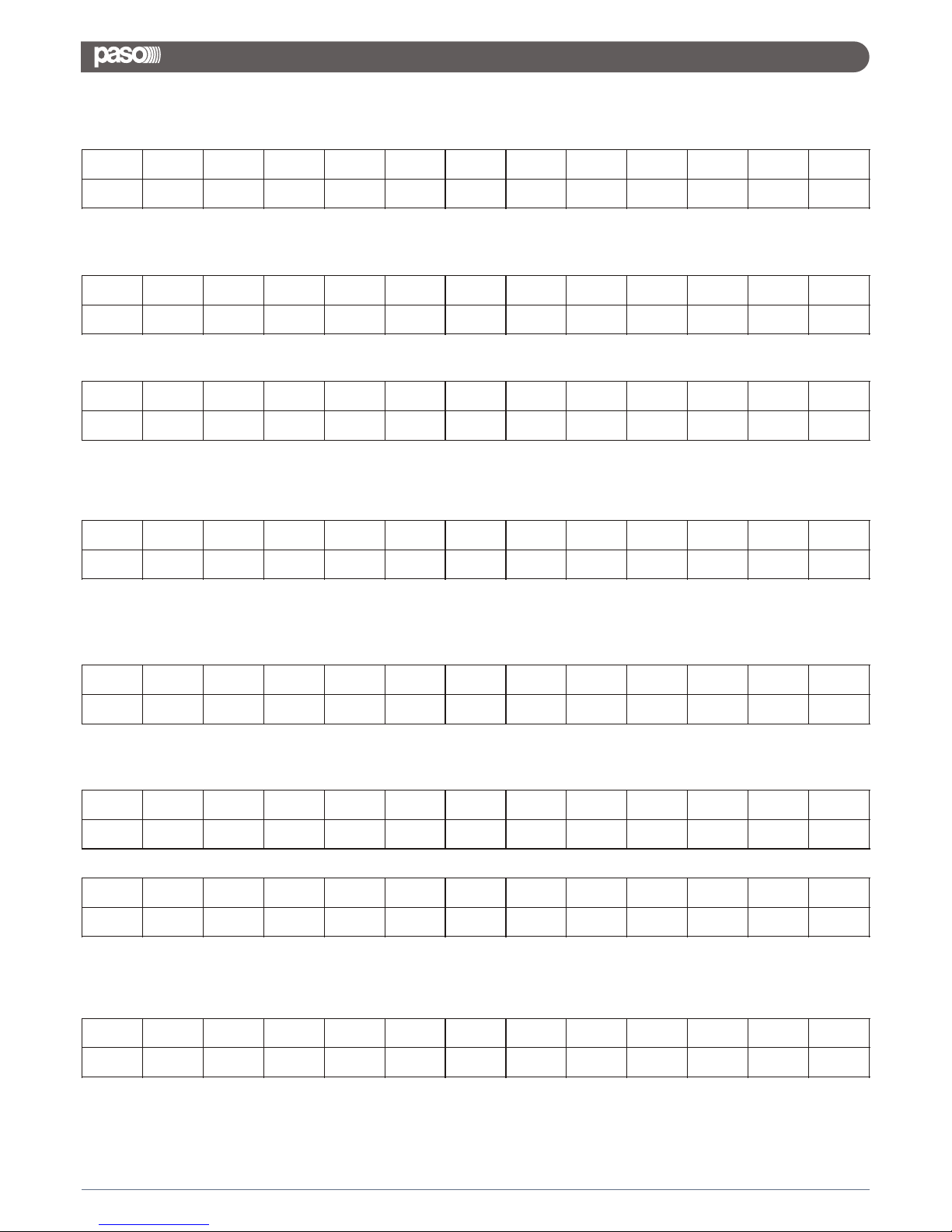
Mode= AutoMixerMode, Value=0,1 where 0=NOM (Number of Open Mic), 1=Gain Sharing
RX:
UPG_AUTOMIX_GS_CMD: CMD=64H
TX:
LEV= AutoMixer_GS_Level, Value=0,..,24 (-12dB to 0dB step 0.5dB)
RX:
UPG_AUTOMIX_NOM_ATT_CMD: CMD=6AH
TX:
Define the attenuation of the MIC(s) when the user use 1,2,..,8 mic, valid only if the mode is
N.O.M
Mic1,...,8= value of the attenuation :0,..,200 (-20dB to 0dB step 0.1dB)
RX:
READ_AUTOMIX_NOM_ATT_CMD: CMD=0EH
TX:
RX:
Mic1,...,8= value of the attenuation :0,..,200 (-20dB to 0dB step 0.1dB)
UPG_DUCKER_PRIORITY_CMD: CMD=66H
TX:
Byp= Ducker priority = 8 bit where LSB=Input1,..., MSB=Input8; Value=0,1 where 0=bypass, 1=not
byp (max number of the channel with priority is 4)
RX:
STX ID_M ID_N CMD D0 D1 D2 D3 D4 D5 D6 D7 ETX
F0H
46H
XX 64H 00H 00H 00H 00H 00H LEV 00H 00H F7H
STX ID_M ID_N CMD D0 D1 D2 D3 D4 D5 D6 D7 ETX
F0H
46H
XX 6AH Mic1 Mic2 Mic3 Mic4 Mic5 Mic6 Mic7 Mic8 F7H
STX ID_M ID_N CMD D0 D1
D2
D3 D4 D5 D6 D7 ETX
F0H
46H
XX 6AH Mic1 Mic2 Mic3 Mic4 Mic5 Mic6 Mic7 Mic8 F7H
STX ID_M ID_N CMD D0 D1
D2
D3 D4 D5 D6 D7 ETX
F0H
46H
XX 3EH 00H 00H 00H 00H 00H 00H 00H Val F7H
STX ID_M ID_N CMD D0 D1
D2
D3 D4 D5 D6 D7 ETX
F0H
46H
XX 0EH 03H D8H 08H 00H 00H 00H 00H Byp F7H
STX ID_M ID_N CMD D0 D1
D2
D3 D4 D5 D6 D7 ETX
F0H
46H
XX 66H 00H 00H 00H 00H 00H 00H 00H Byp F7H
STX ID_M ID_N CMD D0 D1 D2 D3 D4 D5 D6 D7 ETX
F0H
46H
XX 62H 00H 00H 00H 00H 00H 00H 00H Mode F7H
STX ID_M ID_N CMD D0 D1 D2 D3 D4 D5 D6 D7 ETX
F0H
46H
XX 64H 00H 00H 00H 00H 00H LEV 00H 00H F7H
45
DMX 8008
Page 48
This is the acknowledge
UPG_DUCKER_HOLD_CMD: CMD=67H
TX:
Hold = Ducker Hold Time Value=0,..,99 (da 10ms a 1000ms)
RX:
This is the acknowledge
UPG_DUCKER_REL_ATK_CMD: CMD=68H
TX:
Rel = Ducker Release Time Value=0,..,47
Atk = Ducker Attack Time Value=0,..,47
RX:
UPG_DUCKER_THR_CMD: CMD=69H
TX:
Att = Ducker Attenuation level Value=0,..,80
Gate = Ducker gating thr Value=0,..,44
RX:
This is the acknowledge
VUMETER_LIM_CMD: CMD=37H
TX:
RX:
STX ID_M ID_N CMD D0 D1 D2 D3 D4 D5 D6 D7 ETX
F0H
46H
XX 66H 00H 00H 00H 00H 00H 00H 00H Byp F7H
STX ID_M ID_N CMD D0 D1 D2 D3 D4 D5 D6 D7 ETX
F0H
46H
XX
67H
00H 00H 00H 00H 00H 00H 00H
Hold
F7H
STX ID_M ID_N CMD D0 D1 D2 D3 D4 D5 D6 D7 ETX
F0H
46H
XX
67H
00H 00H 00H 00H 00H 00H 00H
Hold
F7H
STX ID_M ID_N CMD D0 D1 D2 D3 D4 D5 D6 D7 ETX
F0H
46H
XX
68H
00H 00H 00H 00H 00H 00H Rel
Atk
F7H
STX ID_M ID_N CMD D0 D1 D2 D3 D4 D5 D6 D7 ETX
F0H
46H
XX
68H
00H 00H 00H 00H 00H 00H Rel
Atk
F7H
STX ID_M ID_N CMD D0 D1 D2 D3 D4 D5 D6 D7 ETX
F0H
46H
XX
69H
00H 00H 00H 00H 00H Att Gate
00H
F7H
STX ID_M ID_N CMD D0 D1 D2 D3 D4 D5 D6 D7 ETX
F0H
46H
XX
69H
00H 00H 00H 00H 00H Att Gate
00H
F7H
STX ID_M ID_N CMD D0 D1 D2 D3 D4 D5 D6 D7 ETX
F0H
46H
XX
37H
00H 00H 00H 00H 00H 00H 00H
00H
F7H
STX ID_M ID_N CMD D0 D1 D2 D3 D4 D5 D6 D7 ETX
F0H
46H
XX
37H
In1 In2 In3 In4 In5 In6 In7
In8
F7H
46
DMX 8008
Page 49
In1,..,I8 are the value already in dB of the Limiter activity(for each output)
dB = 60 - (InX / 2) (max limitazione = 48dB poiche' limiter Thr = -30 to +18 ) (inX = 0,...,120; step dB =
0.5)
VUMETER_CMP_CMD: CMD=38H
TX:
RX:
In1,..,I8 are the value already in dB of the Compression activity (for each output)
dB = 60 - (InX / 2) (max Compression = 48dB poiche' Cmp Thr = -30 to +18 ) (inX = 0,...,120; step dB
= 0.5)
CLOSE ALL DEVICES: CMD=8FH
(only usb and RS485)
TX:
There is not acknowledge.
VUMETER_IN_CMD : CMD=55H
TX:
RX:
In1,..,I8 are the value already in dB of the input signal
dB = -60 + (InX / 2) + 18 (max level=+18) (inX = 0,...,120; step dB = 0.5)
VUMETER_OUT_CMD: CMD=56H
TX:
RX:
In1,..,I8 are the value already in dB of the output signal
dB = -60 + (InX / 2) + 18 (max level=+18) (inX = 0,...,120; step dB = 0.5)
STX ID_M ID_N CMD D0 D1 D2 D3 D4 D5 D6 D7 ETX
F0H
46H
XX
38H
00H 00H 00H 00H 00H 00H 00H
00H
F7H
STX ID_M ID_N CMD D0 D1 D2 D3 D4 D5 D6 D7 ETX
F0H
46H
XX
38H
In1 In2 In3 In4 In5 In6 In7
In8
F7H
STX ID_M ID_N CMD D0 D1 D2 D3 D4 D5 D6 D7 ETX
F0H
42H
XX
8FH
00H 00H 00H 00H 00H 00H 00H
00H
F7H
STX ID_M ID_N CMD D0 D1 D2 D3 D4 D5 D6 D7 ETX
F0H
46H
XX
55H
00H 00H 00H 00H 00H 00H 00H
00H
F7H
STX ID_M ID_N CMD D0 D1 D2 D3 D4 D5 D6 D7 ETX
F0H
46H
XX
55H
In1 In2 In3 In4 In5 In6 In7
In8
F7H
STX ID_M ID_N CMD D0 D1 D2 D3 D4 D5 D6 D7 ETX
F0H
46H
XX
56H
00H 00H 00H 00H 00H 00H 00H
00H
F7H
STX ID_M ID_N CMD D0 D1 D2 D3 D4 D5 D6 D7 ETX
F0H
46H
XX
56H
In1 In2 In3 In4 In5 In6 In7
In8
F7H
47
DMX 8008
Page 50
INC_DECR_GAIN_CMD: CMD=30H
command Increase/Decrease input/output Level
TX:
Where:
Chn = 0,...,15 - In1,..,In8=0,1,2,3,..,7; Out1,...,Out8 = 8,...,15
Flag = 0,1 - decrease level = 0; Increase level = 1;
Value = 0,...x step of the increase/decrease level
if Value = 01h then the level will be increased/decreased of 0.1dB,
if Value = 0Ah then the level will be increased/decreased of 1dB,
if Value = x then the level will be increased/decreased of (0.1 * x) dB.
If the level is to max or min the system maintein the min or max value
RX:
MUTE_UNMUTE_CMD: CMD=33H
single Mute/Unmute input/output
TX:
Chn = 0,...,15 - In1,..,In8=0,1,2,3,..,7; Out1,...,Out8 = 8,...,15
Value = 0,1 0=Unmute; 1=Mute
RX:
INC_DECR_GAIN_LINKED_CMD: CMD=2FH
Increase/Decrease input/output Level linked channel
TX:
Where:
Sel I/O = 0,1 - 0=Input; 1=Output
Flag = 0,1 - decrease level = 0; Increase level = 1;
Value = 0,...,x step of the increase/decrease level
if Value = 01h then the level will be increased/decreased of 0.1dB,
if Value = 0Ah then the level will be increased/decreased of 1dB,
if Value = x then the level will be increased/decreased of (0.1 * x) dB.
ChLink (8bit) = one bit for each input or output (with 1 input/output selected )
Examples
to increase the level of 1dB on input1 and input5, the user must send the following frame:
STX ID_M ID_N CMD D0 D1 D2 D3 D4 D5 D6 D7 ETX
F0H
46H
XX
30H
Chn Flag 00H 00H 00H 00H 00H
Value
F7H
STX ID_M ID_N CMD D0 D1 D2 D3 D4 D5 D6 D7 ETX
F0H
46H
XX
30H
Chn Flag 00H 00H 00H 00H 00H
Value
F7H
STX ID_M ID_N CMD D0 D1 D2 D3 D4 D5 D6 D7 ETX
F0H
46H
XX
33H
Chn 00H 00H 00H 00H 00H 00H
Value
F7H
STX ID_M ID_N CMD D0 D1 D2 D3 D4 D5 D6 D7 ETX
F0H
46H
XX
33H
Chn 00H 00H 00H 00H 00H 00H
Value
F7H
STX ID_M ID_N CMD D0 D1 D2 D3 D4 D5 D6 D7 ETX
F0H
46H
XX
2FH
Sel IO Flag ChLink 00H 00H 00H 00H
Value
F7H
bit7 bit6 bit5 bit4 bit3 bit2 bit1 bit0
In8/Out8 In7/Out7 In6/Out6 In5/Out5 In4/Out4 In3/Out3 In2/Out2 In1/Out1
F0h 46h ID 2Fh 00h 01h 11h 00h 00h 00h 00h Value F7h
48
DMX 8008
Page 51
RX:
INC_DECR_MASTERGAIN_CMD: CMD=31H
Increase/Decrease MasterGain Level (only Input)
TX:
Where
Flag = 0,1 decrease level = 0; Increase level = 1;
Value = 0,...x step of the increase/decrease level
if Value = 01h then the input master level will be increased/decreased of 1%,
if Value = 0Ah then the input master level will be increased/decreased of 10%,
if Value = x then the level will be increased/decreased of (1 * x) %
RX:
INC_DECR_MASTERVOLUME_CMD: CMD=32H
Increase/Decrease MasterVolume Level (only Output)
TX:
Where:
Flag = 0,1 decrease level = 0; Increase level = 1;
Value = 0,...x step of the increase/decrease level
if Value = 01h then the output master level will be increased/decreased of 0.1dB,
if Value = 0Ah then the output master level will be increased/decreased of 1dB,
if Value = x then the output master level will be increased/decreased of (0.1 * x) dB.
RX:
STX ID_M ID_N CMD D0 D1 D2 D3 D4 D5 D6 D7 ETX
F0H
46H
XX
2FH
Sel IO Flag ChLink 00H 00H 00H 00H
Value
F7H
STX ID_M ID_N CMD D0 D1 D2 D3 D4 D5 D6 D7 ETX
F0H
46H
XX
31H
00H Flag 00H 00H 00H 00H 00H
Value
F7H
STX ID_M ID_N CMD D0 D1 D2 D3 D4 D5 D6 D7 ETX
F0H
46H
XX
31H
00H Flag 00H 00H 00H 00H 00H
Value
F7H
STX ID_M ID_N CMD D0 D1 D2 D3 D4 D5 D6 D7 ETX
F0H
46H
XX
32H
00H Flag 00H 00H 00H 00H 00H
Value
F7H
STX ID_M ID_N CMD D0 D1 D2 D3 D4 D5 D6 D7 ETX
F0H
46H
XX
32H
00H Flag 00H 00H 00H 00H 00H
Value
F7H
49
DMX 8008
Page 52

Important information for correct disposal of the product in accordance with EC Directive 2002/96/EC
This product must not be disposed of as urban waste at the end of its working life. It must be taken to a special
waste collection centre licensed by the local authorities or to a dealer providing this service. Separate disposal of
electric and/or electronic equipment (WEEE) will avoid possible negative consequences for the environment
and for health resulting from inappropriate disposal, and will enable the constituent materials to be recovered,
with significant savings in energy and resources. As a reminder of the need to dispose of this equipment
separately, the product is marked with a crossed-out wheeled dustbin.
WARRANTY
This product is warranted to be free from defects in raw materials and assembly. The warranty period is governed by the
applicable provisions of law. Paso will repair the product covered by this warranty free of charge if it is faulty, provided the
defect has occurred during normal use. The warranty does not cover products that are improperly used or installed,
mechanically damaged or damaged by liquids or the weather. If the product is found to be faulty, it must be sent to Paso free of
charges for shipment and return. This warranty does not include any others, either explicit or implicit, and does not cover
consequential damage to property or personal injury. For further information concerning the warranty contact your local PASO
distributor.
Important! Should the user wish to avail himself of servicing under the warranty, he must provide evidence of the purchase
(invoice or receipt). The user shall also indicate the date of purchase, model and serial number indicated on the equipment.
Via Settembrini, 34 - 20020 Lainate (MI) - ITALIA
http://www.paso.it - E-mail: [email protected]
UDT - Ed. 06/15 - 11/768
This product is in keeping with the relevant European Community Directives.
 Loading...