

Page 1
P
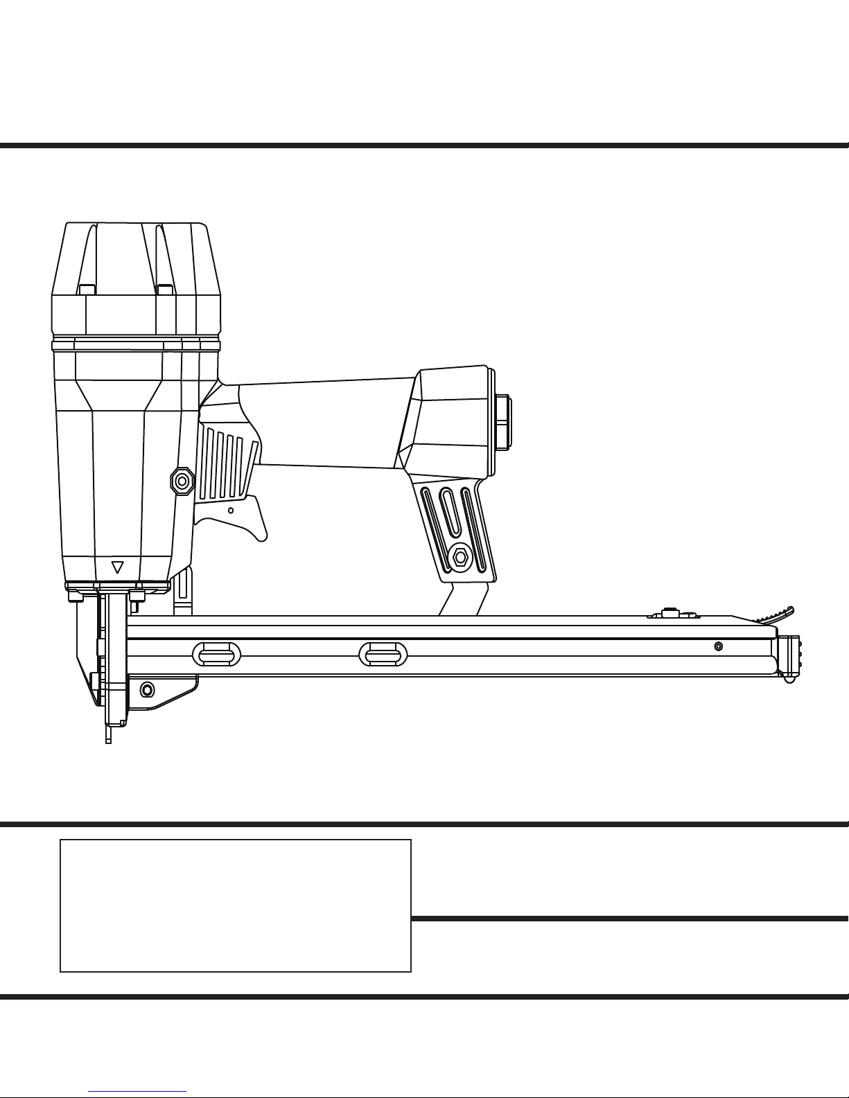
MODEL PCF 1000
Corrugated Fastener
Tool
IMPORTANT!
DO NOT DESTROY
It is the customer’s responsibility to have all
operators and service personnel read and
understand this manual.
PRINTED IN U.S.A.
© 2010, Illinois Tool Works, Inc.
502422-4
OPERATING MANUAL AND
SCHEMATIC
1
Page 2
PARTS LEGEND
PCF 1000,
1 502361 4 Screw
2 1015483 8 Washer
3 502362 1 Top Cap
4 502363 1 Piston Stop
5 502364 1 Spring
6 502365 2 O-Ring
*
7 501621 1 O-Ring
*
8 502366 1 Washer
9 502367 1 Valve
10 502368 1 Valve Assy.
11 502369 1 O-Ring
*
12 502370 1 Piston
13 502371 1 Driver Blade
*
14 502372 1 Bumper
*
15 501625 1 O-Ring
*
16
17
18
19
*
20
21
■
22
■
23
24
25
*
26
27
*
28
29
30
*
31
32
*
33
*
34
*
35
36
*
* Denotes Normal Wear Items.
** Make sure Warning Label (502426) is properly affixed.
Replace if necessary.
Label available at no charge through the Service Parts Dept.
▲ Apply Loctite 242 (Blue) Part No. 093500.
Apply Loctite (Green) Part No. 401491
■
Denotes New Change
➔
.070
502419 1 Driver Blade Seal
502373 1 Noseplate
502374 1 Lower WCE
502428
502375 2 Screw
502376 1 WCE, Spring Cover
1015482 2 Screw
1015506 4 Screw
502377 1 Sleeve Seal
502378 1
502379 1 Sleeve
502380 1 O-Ring
502381 1 Gasket
502382 1 Housing
1015303 1 O-Ring
502383 1 Trigger Valve Housing
501860 1 O-Ring
1015511 1 O-Ring
501418 1 O-Ring
502384 1 Valve Piston
1015514 1 O-Ring
1 Spring, WCE
O-Ring
502360
37
38
*
39
*
40
41
42
43
➔
44
45
46
➔
➔
47
48
49
50
➔
51
52
53
54
55
56
57
58
59
60
61
62
63
*
64
65
502417
66
67
■
68
69
70
71
72
502718 1 Spring
501648
502385
502386
502387
501635
511159
502389
502390
511160
511161
502393
502394
511162
502396
502397
502398
502399
502407
502408
502409
502410
502411
502412
502413
502414
502415
502416
1015317
501696 2 Screw
502420 1 Plate
501140 1 Logo, Housing Left
501141 1 Logo, Housing Right
502426 1 Warning Label
502427 1 Oil Daily Label
2 O-Ring
1 Trigger Valve
1 Bushing
1 Trigger Valve Assy.
1 Screw
1 Nut
2 Screw
1 Support
1 Spacer
1 Pusher
1 Screw
1 Spring
1 Spacer Stop
1 Screw
1 Washer
1 Magazine
1 Nut
1 Latch
1 Screw
1 Spring
1 Slider
1 Spring
1 Roller
1 Pin
1 Inlet Cap
1 O-Ring
1 Trigger Assy.
1 Screw
1 Safety Guide
SAFETY INSTRUCTIONS
WEAR EYE AND HEARING PROTECTION
Always wear hearing protection and eye protection
devices, including side shields when operating or
working in the vicinity of a tool.
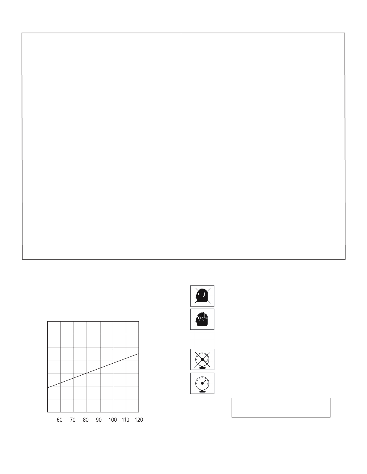
.060
.050
.040
•
.036
.030
SCF
.020
AIR CONSUMPTION - SCF / FASTENER
.010
AIR PRESSURE - PSIG
DO NOT EXCEED MAXIMUM
RECOMMENDED AIR PRESSURE
Operate the tool using only the recommended air
pressure. Do not exceed the maximum air pressure
marked on the tool. Be sure the air pressure gauge is
operating properly and check it at least twice a day.
Never use any bottled air or gases such as oxygen
to operate the tool since they could cause the tool
to explode.
10
Page 3

❂
80
1
24
PCF 1000
502360
2
25
26
3
4
27
28
5
29
62
6
63
64
52
65
66
❂
45
10
11
12
7
72
8
9
6
70
69
30
31
32
33
34
35
41
36
37
38
13
14
15
16
17
18
19
67
❂
45
42
43
❂
62
44
45
68
❂
80
❂
62
20
21
22
Always Wear
Safety Glasses
2
23
❂
80
46
47
39
40
❂
62
48
❂
45
49
50
❂
51
62
52
71
53
54
55
❂
45
56
57
58
59
60
61
When Using
Power T ools
401382
11
❂
Torque Values
IN•LBS
Page 4

ACCESSORIES
ubricants and Loctite
L
Loctite 242 (Blue)
Loctite 620 (Green)
Lubricating Oil 16 oz.
Lubricaing Oil with Anitfreeze 8 oz.
Chemplex 710 Lubricant 1lb.
Part No. 093500
Part No. 401491
Part No. 403720
Part No. 219090
Part No. 403734
Tool Cleaner
®
Ideal cleaner for all Paslode tools. Part No. 219348
Safety Glasses
Clear
Part No. 401382
Sequential Trigger kit
(SILVER/GREY TRIGGER)
Piston Removal Tool
Piston Removal
13
• Piston unlocking
12
Part No. 502424
Part No. 502421
P
An Illinois Tool Works Company
888 Forest Edge Drive
Vernon Hills, Illinois 60061-3105
16
 Loading...