

Page 1
P
CORDLESS
IM200/50 S16
CORDLESS
STAPLER
IMPORTANT!
DO NOT DESTROY
It is the customer's responsibility to have
all operators and service personnel read
and understand this manual.
Printed in U.S.A.
© 2002 Illinois Tool Works, Inc.
403627-7
2/02
OPERA TING AND
SAFETY MANUAL
19
Page 2

Contents
Subject Page
Introduction and Warranty............................................... 2
An Overview of the Cordless Stapler .............................. 3
Safety Instructions...........................................................4
Battery and Charger........................................................ 7
Fuel Cell and Metering Valve .......................................... 9
Preparing the Cordless Stapler for Use ........................ 12
Cordless Stapler Operation ...........................................13
Fasteners and Applications........................................... 14
Servicing ....................................................................... 15
Troubleshooting ............................................................ 17
The Impulse® battery charger system meets all safety
requirements for power tools.
is a trademark
P
CORDLESS
Power Nailers are made in the U.S.A. and are
P
CORDLESS
protected by one or more of the following U.S. patents:*
4,403,722 4,483,280 4,483,474 4,522,162
*Other patents issued and pending.
Paslode® is a member of:
Paslode
An Ilinois Tool Works Company
888 Forest Edge Drive
Vernon Hills, Illinois 60061
1
Page 3

Introduction and Warranty
Cordless Stapler Operating Manual
This manual is intended to acquaint you with the Paslode
Cordless Stapler. Unlike other power fastening tools, the
Cordless Stapler is powered by an internal combustion
linear motor. In simpler terms, your Cordless Stapler is
powered by a motor similar to the one that powers an
automobile. The Cordless Stapler ignites a fuel and air
mixture to produce the energy to drive the motor, which in
turn drives the fastener. As you will see, the Cordless
Stapler is totally self-contained. It carries its own fuel supply
and battery, along with a supply of fasteners.
For ease of use, this manual is divided into sections (see
Contents). Each section of the manual is written with you,
the tool operator, in mind. We have left out all of the technical
terms so that you can readily understand how to get the
maximum performance from your Cordless Stapler, and
how to avoid damaging the tool or injuring yourself. But, to
accomplish this, we need you to do two things:
1. READ THE MANUAL FROM COVER TO COVER
BEFORE USING THE TOOL.
2. FOLLOW ALL INSTRUCTIONS IN THE MANUAL.
The Cordless Stapler should be handled like other power
fastening tools that you use. Like most tools, when used
improperly it could result in injury. If you are going to allow
others to use the Cordless Stapler, it is your responsibility
to make sure that they also read and comply with the
instructions in this manual before attempting to operate
the tool.
Should you have questions about the Cordless Stapler ,
or wish to obtain additional copies of this manual, please
contact your Paslode® representative. The space below is
provided so that you may record your representative's
name, address, and telephone number.
My Paslode representative is:
Name
Address
City State Zip
Impulse® Warranty and Limitations
Paslode warranty that new Cordless power fastening tools, parts
and accessories will be free from defects in material and
workmanship for the period shown below, after the date of
delivery to the original user.
ONE-YEAR LIMITED WARRANTY
A one-year warranty will apply to all parts, except those listed
below as normal wearing parts, or parts which are specifically
covered by an extended warranty.
FIVE-YEAR EXTENDED LIMITED WARRANTY
A five-year warranty will apply to all molded nylon parts:
• Motor Housing, Cap and Grille
• Handle Halves and Actuator
• Trigger
90-DAY LIMITED WARRANTY
A 90-day warranty applies to the following parts, which are
considered normal wear parts:
• Bumper
• Driver Blades
• O-Rings
• Piston Rings
Telephone Number
WARRANTY STATEMENT
Paslode's sole liability hereunder will be to replace any part or accessory
which proves to be defective within the specific time period. Any replacement
part or accessory provided in accordance with this warranty will carry a
warranty for the balance of the period of warranty applicable to the part it
replaces. This warranty does not apply to part replacement required due
to normal wear.
This warranty is void on any tool which has been subjected to misuse,
abuse, accidental or intentional damage, use with fasteners, fuel, batteries,
or battery chargers not meeting Paslode specification, size, or quantity,
improperly maintained, repaired with other than genuine Paslode
replacement parts, damaged in transit or handling, or which, in Paslode's
opinion, has been altered or repaired in a way that affects or detracts from
the performance of the tool.
PASLODE MAKES NO WARRANTY, EXPRESSED OR IMPLIED,
RELATING TO MERCHANTABILITY, FITNESS, OR OTHERWISE,
EXCEPT AS STATED ABOVE, and Paslode's liability AS STATED ABOVE
AND AS ASSUMED ABOVE is in lieu of all other warranties arising out of,
or in connection with, the use and performance of the tool, except to the
extent other wise provided by applicable law. PASLODE SHALL IN NO
EVENT BE LIABLE FOR ANY DIRECT, INDIRECT, OR CONSEQUENTIAL
DAMAGES, INCLUDING, BUT NOT LIMITED TO, DAMAGES WHICH
MAY ARISE FROM LOSS OF ANTICIPATED PROFITS OR
PRODUCTION, SPOILAGE OF MATERIALS,, INCREASED COST OF
OPERATION, OR OTHERWISE.
Paslode reserves the right to change specifications, equipment, or designs
2
Page 4
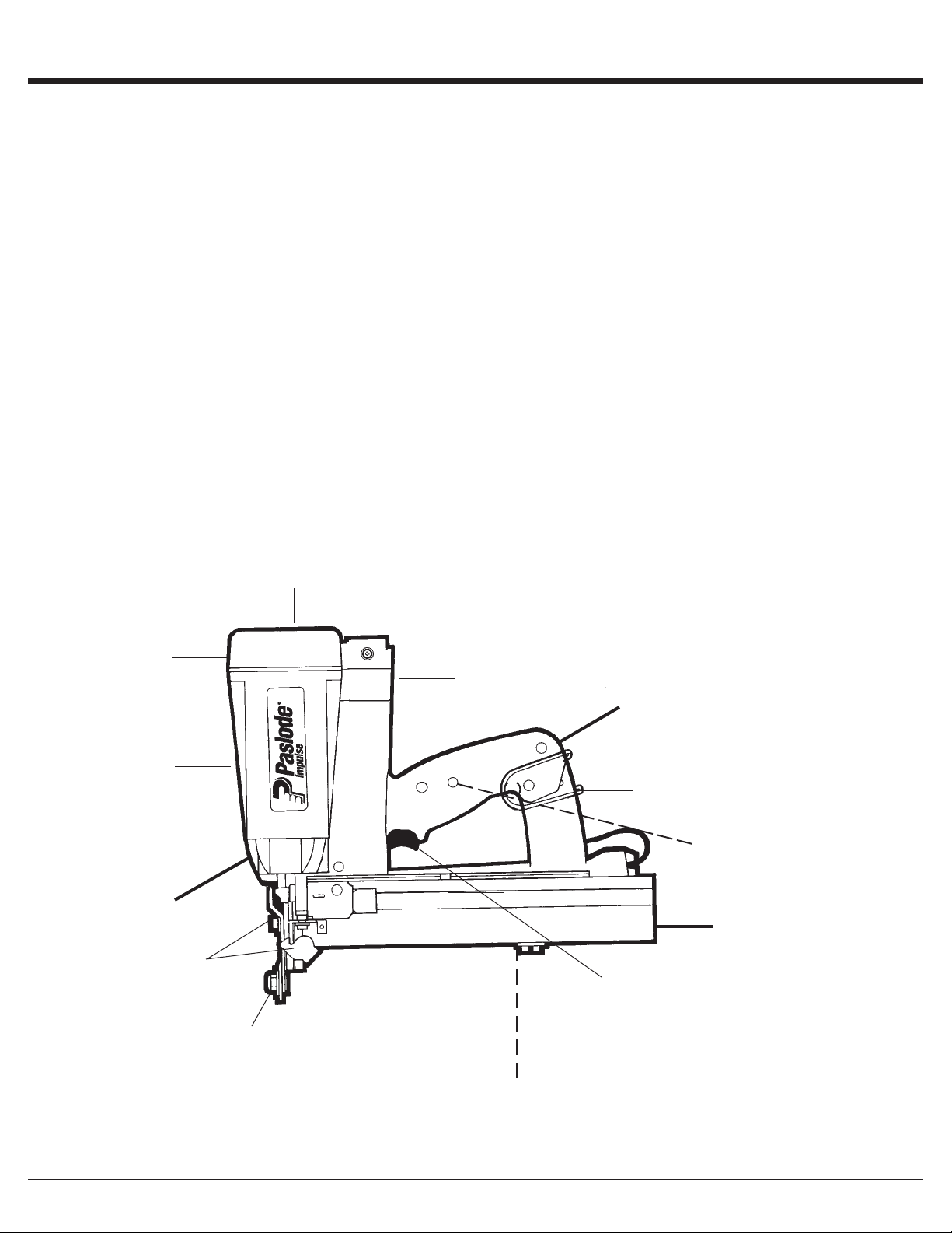
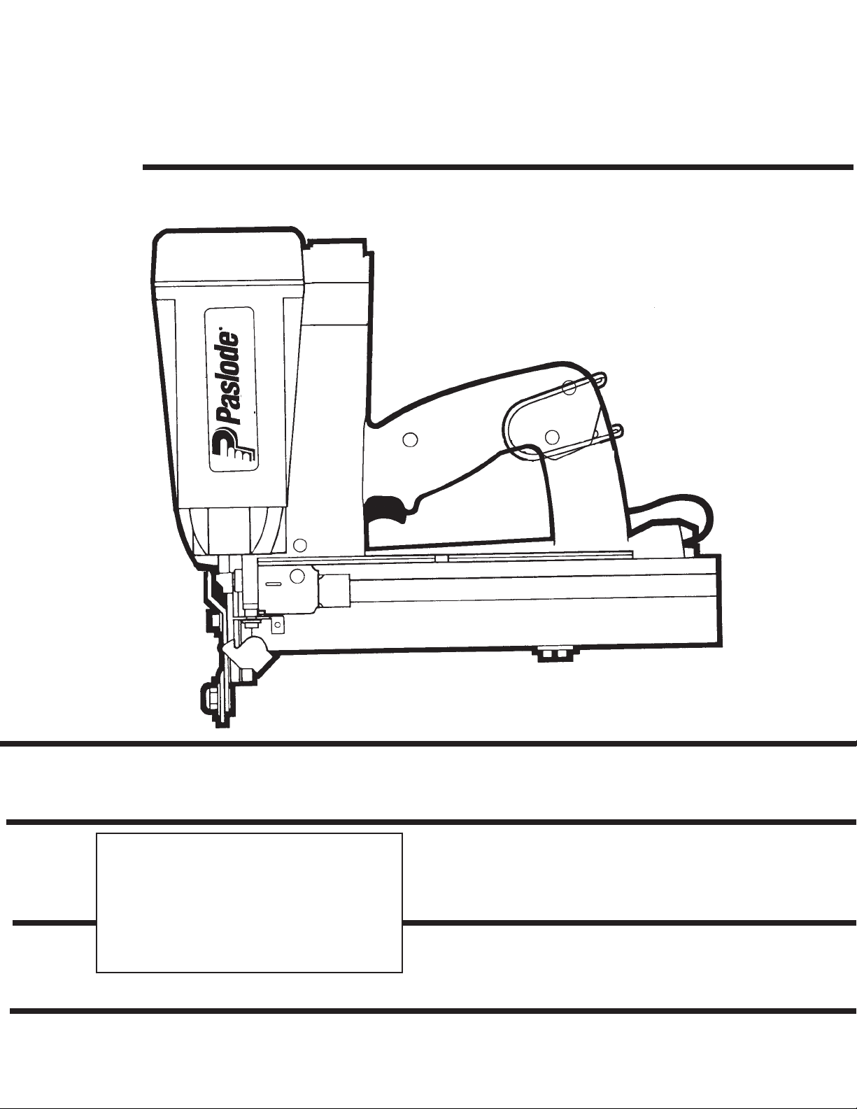
An Overview of the Cordless Stapler
Description
The Cordless Stapler is a self-contained, fully portable tool
that uses liquid hydrocarbon fuel to power a unique linear
drive internal combustion motor.
In order for you to fully understand the information contained
in this manual, you need a basic understanding of the
Cordless Stapler. As you can see in the illustration below,
the Cordless Stapler is made up of three separable
assemblies: handle, motor and rail.
As you examine the Cordless Stapler, become familiar with
the three major assemblies and the various components
located in each of them.
The Handle Assembly contains the fuel cell, the battery
indicator light, and the trigger.
The Motor Assembly contains the cover and filter, the
motor housing, the nose, and the work contacting element.
The Rail Assembly contains the components to load and
control the specfic fastener for the Impulse Stapler.
cover & filter
Specifications
Dimensions: Weight 6.5 lbs.
Height 12-1/2 nches
Length 13-1/2 inches
Cycle Rate: Intermittent Operation – 2 to 3 staples
per second
Continuous Operation – 500 staples
per hour
NOTE: Exceeding these rates could cause tool to overheat,
resulting in loss of performance or damage to tool
components.
By using the Cordless Stapler at its recommended cycle
rate, you will be able to drive several thousand nails in a
typical workday.
Fasteners: 16 gauge, Std. Crown Staples
Rail Capacity: 2 strips, or 150 fasteners
Battery : 6 volts DC - Provides enough energy to
drive approximately 4000 fasteners on a full
charge.
Fuel Cell: Liquid hydrocarbon - Provides enough fuel
to drive approximately 2400 fasteners.
cap
motor housing
Motor Assembly
Quick Clear
fuel cell compartment
Handle Assembly
belt hook
battery indicator light
(opposite side)
Rail Assembly
trigger
follower
Adjustable
guide
battery compartment
(opposite side)
3
Page 5
Safety Instructions
The following safety instructions have been included in this
booklet to provide you with basic information necessary for
safe operation of the Paslode Stapler. DO NOT ATTEMPT
TO OPERATE THIS TOOL UNTIL YOU HAVE READ AND
UNDERSTAND ALL SAFETY PRECAUTIONS AND
MANUAL INSTRUCTIONS.
In addition to these instructions, training may be necessary.
Contact your Paslode representative for additional
information.
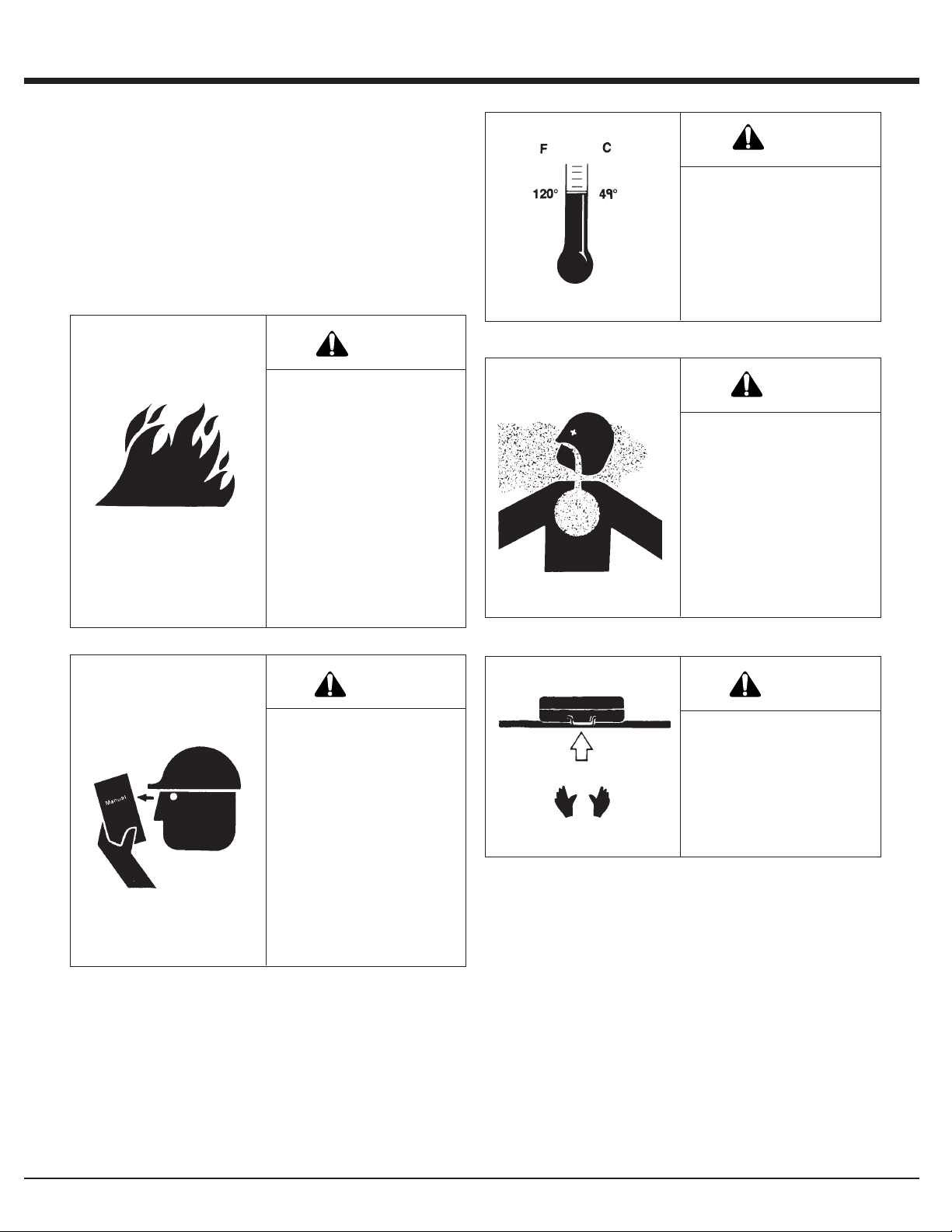
DANGER
WARNING
Do not expose the tool to
temperatures in excess of
120° F (49° C). Fuel and/
or the battery may burst,
releasing flammable gas.
The Cordless Stapler is an
internal combustion
device. It produces hot
exhaust gases that may
ignite flammable
materials. This tool must
not be used in a
combustible environment
or in the presence of
combustible materials,
such as flammable
chemicals, adhesives,
gasoline, or solvents.
WARNING
Do not attempt to operate
this tool until you have
read and understood all
safety precautions and
manual instructions.
Failure to follow all safety
precautions and
instructions may result in
a permanent loss of vision,
serious personal or even
fatal injury, property
damage and/or tool
damage.
WARNING
This tool must be operated
only in a well-ventilated
environment, because
the tool exhausts carbon
monoxide similar to a gas
chainsaw or lawnmower.
Exposure to carbon
monoxide may cause
dizziness, nausea, or
unconsciousness.
WARNING
ALWAYS keep the
Cordless Stapler, fuel cell,
battery and battery
charger out of the reach
of children.
4
Page 6

WARNING
Always wear EYE and
EAR safety gear when
working with or in the
vicinity of the Cordless
Stapler.
Safety Instructions
CONTACTING ELEMENT.
This device helps reduce the possibility of accidental
fastener discharge by preventing the tool from operating
until it is completely against the work surface.
NEVER operate the tool if the work contacting element
is not working properly.
8. ALWAYS POINT THE TOOL AWAY FROM
YOURSELF AND OTHERS WHEN CLEARING JAMS
OR REMOVING FASTENERS.
1. Eye protection must meet the requirements of ANSI
Standard Z87.1 and should have side shields for
increased protection.
2. NEVER ASSUME THE TOOL IS EMPTY.
Never point the tool at yourself or anyone else.
3. NEVER ENGAGE IN "HORSEPLAY" WITH THE TOOL.
The Cordless Stapler is not a toy – it is a tool. Careless
and improper use may result in a serious accident.
4. NEVER CARRY THE TOOL WITH YOUR FINGER ON,
OR SQUEEZING, THE TRIGGER.
This practice may result in the accidental discharge of
a fastener.
5. NEVER OPERATE A MALFUNCTIONING TOOL.
Refer to the servicing or troubleshooting section of this
manual to correct the problem. If the problem cannot be
corrected, stop using the tool and report it to your
supervisor or Paslode® representative.
6. DO NOT LOAD FASTENERS WITH THE TRIGGER
AND/OR WORK CONTACTING ELEMENT PRESSED
IN.
A fastener may be accidentally discharged.
Pull the follower slightly back and push the release
lever. Tip the tool nose up slightly and fasteners should
slide out of the rear of the magazine. If fasteners are
jammed, refer to the appropriate servicing section of
this manual.
9. NEVER OPERATE THE IMPULSE STAPLER IF
PARTS ARE LOOSE, DAMAGED OR MISSING.
10. DO NOT DRIVE FASTENERS INTO KNOTS OR ON
TOP OF OTHER FASTENERS.
A fastener may ricochet and cause serious injury.
11. OPERATE THE TOOL ONLY ON THE WORKPIECE.
WARNING
The Cordless Stapler
should be operated only
when it is in contact with
the work surface. When
fastening thin materials
such as plywood, be sure
to position the tool so that
the fastener is driven into
the underlying piece.
7. NEVER REMOVE OR DISABLE THE WORK
5
Page 7

Safety Instructions
12. NEVER DRIVE FASTENERS INTO AREAS WITH
CONCEALED HAZARDS.
Always check the area behind the work surface for
electrical wiring, gas pipes, water pipes, sewer drains or
other potential hazards.
13. ALWAYS MAINTAIN SECURE AND UNOBSTRUCTED
FOOTING WHEN ON LADDERS, PLATFORMS OR
OTHER HIGH LOCATIONS.
WARNING
Never over-reach, since
tool recoil may cause a
loss of balance. Always
be aware of edges and
drop-offs when nailing on
rooftops and other high
locations. Keep them in
full view.
14. ALLOW ONLY QUALIFIED PERSONNEL TO OPERATE
THE CORDLESS STAPLER.
15. PROPERLY STORE FUEL CELL.
WARNING
Always store fuel cells
where they will not be
exposed to an open
flame, sparks or
temperatures above 120°
F (49° C).
16. ALWAYS STORE THE TOOL WITH THE FUEL CELL
AND BATTERY REMOVED.
Store the fuel cell in the case with the Cordless
Stapler.
17. KEEP THE TOOL CLEAN.
A clean tool is less likely to jam or malfunction.
18. KEEP YOUR HANDS CLEAR OF THE WORK AREA
SURFACE.
WARNING
WARNING
Only persons who have
read and fully understand
all tool operation, safety
and maintenance
instructions should be
allowed to operate the
tool.
Battery Disposal:
The Impulse battery contains cadium and must be recycled or disposed of properly. It is illegal in some areas to
place a nickel-cadium battery into the trash or solid waste stream. You may contact your local recycling center for
information on where to return the spent battery or call 1-800-822-8837 for information on Ni-Cd battery recycling in
your area.
A fastener may exit at an
angle unexpectedly and
cause injury.
6
Page 8

Battery and Charging System
Battery and Charging Sytem
The Paslode Cordless tool comes with a rechargeable battery and its own charging system. This
battery and charging system combination is the only
one that will work with the Cordless tool. The first
step in preparing a new tool for operation is to fully
charge the battery. New batteries are shipped
discharged and must be charged prior to first
use. Batteries will take 5 minutes to 2 hours (time
will be dependant on the amount of discharge within
the battery) to recharge.
Important Charging Notes
Warning
CHEMICAL/EXPLOSION
HAZARD
Read ALL instructions before charging or using battery. Failure to follow ALL
instructions may result in
fire, severe burns, or release of toxic materials.
Charging Instructions
1. Remove wall mount unit with the orange label from
the tool case and plug into a 120V AC outlet. Set
orange charger on a stable surface and insert wall
mount unit’s plug into plug receptacle on the back of
the charger (see picture). A green light indicates
power is on and charger circuit is ready.
2. Remove the battery from tool or case and insert
terminals down into charger. The red light will come
on indicating that the battery is charging and the
green light will go out.
NOTE
If battery is completely discharged, the red and
green lights may flash back and forth for up to 20
minutes. This safety feature slowly recharges the
battery until it is ready to accept the full charging
current. If the red and green light continue to flash
after 20 minutes, replace the battery.
3. After charging, the red light will go out and the green
light will come on, indicating that the battery is fully
charged. The charger will keep the battery at full
charge until it is removed.
Battery Disposal:
The Impulse battery contains cadmium and must be
recycled or disposed of properly. It is illegal in some
areas to place a nickel-cadmium battery into the trash
or solid waste stream. You may contact your local
recycling center for information on where to return the
spent battery or call 1-800-822-8837 for information on
Ni-Cd battery recycling in your area.
Wall Mount Unit
Plug
THE IMPULSE® CHARGING SYSTEM
REAR VIEW OF
CHARGER BASE
Plug Receptacle
Charger Base
4. Unplug the wall mount unit from the charger and
remove the wall mount unit from the 120V AC outlet.
CHARGING TIMES:
First charge 2 hours
Discharged Battery 5 minutes to 2 hours
CHARGING DON'TS:
1. Do not charge battery outdoors or in temperatures
below 40°F (5°C).
2. Do not allow metal objects to come in contact with
battery terminals.
3. Do not puncture or attempt to open battery case or
cells.
4. Do not store battery where it will be subjected to
temperatures above 120°F (49°C).
5. Do not incinerate battery.
6. Do not use a defective battery charger, one that
over-heats and/or smokes when plugged in.
7. Do not immerse the battery in water.
Impulse® Cordless Accessories:
Battery Charger Kit - Part No. 900200
Wall Mount T ransformer* - Part No. 900477
Battery Charger Base* - Part No. 900476
Automotive Adapter* - Part No. 900507
* Cannot use with previous (gray in color) charging system
components.
7
Page 9

Battery and Charging System
Inserting Battery
Battery Indicator Light
The illustration is a close-up of the side of the Impulse
Stapler handle. On the back side of the handle is a small
plastic lens. This is the battery indicator light.
When you insert a fully-charged battery into the tool, you will
see a blinking green light. If the indicator light blinks red,
recharge the battery.
1. Load the battery, contacts first, into the Impulse
Stapler.
2. Align tabs on the battery compartment cover.
3. Press cover in firmly. Turn cover clockwise to secure.
NOTE: If battery is left in tool for an extended period, the
battery will discharge completely and will require recharging.
®
8
Page 10

Fuel Cell and Metering Valve
Fuel Cell
DANGER
EXPLOSION/FIRE
HAZARD
Read ALL safety
instructions before using
or handling the fuel cell.
Failure to follow ALL
instructions may result in
explosion or fire. This may
cause severe personal
injuries or property
damage.
Keep the fuel cell away
from heat, sparks and
open flame.
Exposure to temperatures
above 120°F (49°C) may
cause the fuel cell to burst,
releasing flammable gas.
There is a second container inside the fuel cell. The inner
container holds the fuel. The space between the inner
container and the outer cylinder is filled with a gas, called the
propellant, which is under pressure.
To eject the fuel, propellant pressure squeezes the inner
fuel container, much as you squeeze a tube of toothpaste.
This squeezing action ensures that all the fuel is used, and
that the Cordless Stapler can operate in any position.
Because of this container-within-a-container design, you
might hear the sound of fluid when shaking the fuel cell after
all the fuel has been used. This is the propellant, which
remains between the containers even after all the fuel has
been expelled.
If you expose the empty fuel cell to extreme temperatures,
the propellant gas will expand and could cause the container
to burst, releasing flammable gases.
Metering Valve
The metering valve contains a fuel metering system to inject
the correct amount of fuel into the combustion chamber.
The yellow metering valve is the only valve that will operate
properly with the Impulse® Stapler.
WARNING
Sunlight can raise the inside temperature of an
unventilated car or van to above 140°F (60°C).
Do not puncture or attempt to open the fuel cell; it is
non-refillable.
Do not incinerate, reclaim or recycle the fuel cell.
Do not smoke while installing or operating the metering
valve.
Do not inhale the spray.
Keep out of the reach of children.
Store fuel cell(s) in well-ventilated areas only.
NOTE
1. Do not attempt to reuse the metering valve!
Replace with fresh fuel cell/valve, and dispose of
spent cell/valve properly.
2. When replacing fuel cell also clean or replace the
air filter for optimum tool operation.
NOTE: Altitude Restriction
Paslode Cordless tools are powered by an internal
combustion engine and are effected by altitude. The
tool may lose power or not cycle consistently at
elevations of 4000 feet or greater. When using the tool
at elevations of 4000 feet it is recommended to use the
blue high altitude fuel metering valve part #219247.
9
Page 11

Fuel Cell and Metering Valve
Installing Metering Valve to Fuel Cell Prior to Use
To install the metering valve to a fuel cell:
1. Press downward on the front side of the valve (stem side) until it seats.
2. Press downward on the rear side of the valve until it seats.
3. The valve is now completely seated onto the fuel can and can be inserted into the tool.
1. 2. 3.
NOTE: Impulse fuel cell are marked with an expiration date on the bottom of the can.
For maximum performance use fuel before expiration date.
DANGER
Impulse Fuel is flammable.
Do not smoke when installing the metering valve!
10
Page 12

Fuel Cell and Metering Valve
Inserting Fuel Cell
Inserting the metering valve/fuel cell assembly into the
Cordless Stapler is very simple. To begin, press up at the
bottom of the actuator cover and pivot outward to open. The
cover will swing out of the way.
1. PRESS UP
2. PULL OUT
As you slide the metering valve/fuel cell assembly into the
Cordless Stapler, you will notice a yellow adapter at the top
of the cylinder pocket. As shown in the illustration, this
adapter is designed to ensure that the metering valve stem
is properly aligned with the small hole, or orifice, that leads
to the combustion chamber. Insert the metering valve stem
into the orifice of the yellow-colored adapter.
Next, with the metering valve stem pointed toward the front
of the tool, insert the metering valve/fuel cell assembly.
Close the actuator cover to complete the loading of fuel in
the Cordless Stapler. Do this by swinging it up and over the
fuel valve/cylinder assembly, and pushing down until the
actuator cover snaps into position.
1. SWING UP
2. PUSH DOWN
11
Page 13

Preparing the Cordless Stapler for Use
Fasteners
The Cordless Stapler drives Paslode® S16 Staples. They
are made from 16-gauge galvinized wire and completely
coated with Pas-Kote for improved holding power. The
use of staples that do not meet Paslode standards could
cause tool damage and will void all warranty claims.
Loading Fasteners
When no fasteners are visible, two full strips of Paslode
staples may be loaded. If fasteners are visible, one full
strip may be loaded.
P
The illustration above shows how to properly load fasteners
into the Cordless Stapler. To load:
1. Draw back the follower until it latches with the follower
latch.
2. Insert one or two strips of Paslode staples onto the rail.
Let them fall forward to the staple guide.
NOTE: Altitude Restriction
Paslode Cordless tools are powered by an
internal combustion engine and are effected by
altitude. The tool may lose power or not cycle
consistently at elevations of 4000 feet or greater.
When using the tool at elevations of 4000 feet it is
recommended to use the blue high altitude fuel
metering valve part #219247.
Cordless Stapler and Outdoor
Weather
Use the Cordless Stapler outdoors, in clear weather,
when the stapler, fuel cell, and battery are between
20°F (-7°C) and 120°F (49°C).
HOT WEATHER OPERATION
The Cordless Stapler requires cooling of the motor
assembly to operate properly. The fan normally
provides the necessary air flow to permit continuous
operation. Whenever the Cordless Stapler is idle for
extended periods, keep the fuel and tool out of direct
sunlight and in surroundings where temperatures will
not exceed 120°F (49°C). After extended periods of
continuous use, it may be necessary to cool the
Impulse motor by setting tool aside for 10-15 minutes
or until the tool operates normally. An overheated tool
may not drive staples completely or may operate
erratically.
3. Locate the follower behind the staples. Release follower
latch. The constant force spring will locate the follower
behind the staples and apply a constant pressure on
them.
Dirt and debris may interfere with proper feeding of fasteners.
Keep the fastener track clean.
CAUTION
The Cordless Stapler should not be used in the rain
or where excessive moisture is present. The use of
the Cordless Stapler under these conditions may
result in damage to tool components and cause tool
to malfunction.
12
COLD WEATHER OPERATION
Fuel cells at cold temperatures lose the required
propellant force. Bring the tool, battery, and fuel cell
above minimum operating temperature without direct
exposure to flame, and check the battery.
CAUTION
This tool must be operated in a well ventilated
environment, because the tool exhausts carbon
monoxide similar to a chainsaw or lawn mower.
Exposure to carbon monoxide may cause dizziness,
nausea or unconsciousness.
Page 14

2
PRESS WORK –
CONTACTING
ELEMENT
AGAINST THE
WORK SURFACE.
Fan motor starts,
fuel is injected into
combustion
chamber and
mixed with air by
the fan.
SQUEEZE
TRIGGER
Spark plug sparks
and fuel/air mixture
ignites.
Combustion
powers piston
assembly driving
fastener.
LIFT TOOL RELEASE
TRIGGER
Combustion
chamber opens.
Fan exhausts hot
gases and cools
internal
components.
Cordless Stapler Operation
Depth of Drive Adjustment
Remove the battery before adjusting the depth of drive.
The depth of drive adjustment is made by simply loosening
the 3/8" hex nut, adjusting to desired depth and retightening
the hex nut.
Dual Function of the Work Contacting
Element:
The Cordless Stapler has the unique feature of a dual
function contacting element.
For Siding Applications:
Loosen the 3/8" hex nut and adjust the work contacting
element up or down for staple standing height.
picture)
For Sheathing Applications:
Remove the 3/8" hexnut.
Remove the work contacting element.
Turn the work contacting element upside down
Replace the washer and tighten the hex nut down.
(see above
DANGER
The work contacting element and nose will become hot
after prolonged or rapid use. If it becomes necessary to
adjust the work contacting element, avoid touching with
bare hands.
NOTE
The stapler will "blank fire" or cycle even if the
magazine is empty of nails. Blank firing will create
driver blade marks on the workpiece, and excessive
impact on the bumper which may result in premature
failure of the bumper.Therefore, load the Cordless
Stapler when required and only cycle it when staples
are in place.
13
Page 15

Fasteners and Applications
Fasteners
The Cordless S16 Stapler drives Paslode S16 Series
staples. They are made from 16-gauge galvanized wire and
are entirely coated with Pas-Kote for improving holding
power. Fasteners are collated into strips of 75 for easy
loading.
Applications
Vinyl Siding
Vinyl Clad Steel
Light Decking
Remodeling
Soffits
14
Page 16

Servicing
Restrict Field Service to the Following
CHECKING THE ENERGY LEVEL OF THE BATTERY
RECHARGING THE BATTERY
CHECKING THE FUEL CELL AND METERING VALVE
REPLACING THE FUEL CELL
CLEANING THE AIR FILTER
CLEARING A JAM
CLEANING THE TOOL (See cleaning manual)
Attempts to go beyond these procedures could result in
serious personal injury or damage to theCordless Stapler
and voiding the warranty.
There are certain problems you may encounter when you
are using the Cordless Stapler that you will be able to correct
on the work site. The following field service procedures are
the only service procedures you should attempt. Anything
else that may appear wrong with the Cordless Stapler
should only be diagnosed and repaired by a fully trained
service technician. If you have any reason to believe that
your problem is beyond the service procedures in this
manual, contact your Paslode® representative immediately.
DANGER
Never attempt any maintenance of the Cordless Stapler
without first removing the fuel cell and battery.
Maintenance should be started only after the tool is
completely inoperative.
Battery Check
Periodically check on the battery indicator light - the light
in the handle of the Cordless Stapler. When encountering
a problem, the first step should always be to make sure the
battery has enough energy to operate the tool.
Fuel Cell Check
If the Cordless Stapler's fan operates and the indicator light
is green, but the tool will not cycle or does not drive
fasteners completely, check the fuel cell. With the fuel cell
out of the tool, check to see if the cell still contains fuel and
that the metering valve is working. To determine if there is
any fuel left in the fuel cell, hold in the upright position and
simply place the metering stem against a solid object, and
gently push about three or four times. A small amount of fuel
should be released each time.
DANGER
Never perform this test near an open flame or sparks,
while smoking, or where the fuel may get into your eyes.
If fuel is not released with each operating of the metering
valve, this indicates that there is no more fuel left in the
cylinder and it must be replaced. Dispose of the empty fuel
cell properly.
Clearing a Jam
A typical problem you may encounter is having a jammed
fastener. Because of the unique design of the Cordless
Stapler, clearing a jammed fastener is easy:
1. Remove the battery.
2. Pull follower back until it latches with rail cover.
3. Push latch, releasing front guide. Pivot front guide
forward.
4. Clear jam, and push driver blade back up to its normal
position.
5. Close front guide and latch it. Check that work contacting
element is free.
6. Release follower.
When the work contacting element is depressed on work
piece, the fan motor will turn on and the blinking green
indicator light will turn solid green. If the indicator light blinks
red or glows red, recharge the battery.
15
Page 17

Servicing
Clearing a Jam (continued)
Make certain magazine mounting screws are tight and
magazine is tight to nose. Attempting to fire tool with a loose
magazine will result in loss of staple control, damage to tool,
or staple discharge toward operator.
Air Filter
Open the cover by pressing slightly above the yellow
adapter, and pivoting the cover open. The air filter simply
lifts out.
Tap the filter GENTLY to remove any dust. Check and clean
the air filter every two days. Soap and water restores the
filter to a "like new" condition.
When you get home:
1. Place the battery in its charger if it needs charging as
indicated by the red charge light on the handle.
2. Wipe your Cordless Stapler with a clean, soft cloth.
3. Remove and clean the filter every two days.
4. Check work contacting element to ensure it is operating
freely.
Impulse
A variety of accessories are available for the Impulse
Stapler:
Battery - Part No. 402500
Extra battery allows use of one battery while spare battery
is being charged.
Tinted Safety Glasses - Part No. 402512
Cuts glare while affording eye protection.
®
Cordless Accessories
End-of-Workday Routine
At the end of each workday, conduct an end-of-workday
routine. These simple steps are based on maintaining the
safety and operational efficiency of the Cordless Stapler.
Before you leave the work site:
1. Remove battery and store in tool case. Always use the
Cordless Stapler case for transporting and storing the
tool.
Clear Safety Glasses - Part No. 402510
Impulse® Oil - Part No. 401482
Battery Charger Kit - Part No. 900200
Cordless Stapler Case - Part No. 900362
Contact your Paslode® representative for additional
information.
Impulse® Tools
A 5/32 Hex Socket Wrench (Part No. 401331 ) is provided
with each Impulse Stapler.
2. Dispose of all empty fuel cells. Remember to dispose of
these cells where they will not be found by children,
crushed, punctured, or burned.
16
Page 18

Troubleshooting
Preparing Tool for Operation - Battery/Charger Problems
SYMPTOM POSSIBLE PROBLEMS SERVICE
Battery does not appear to accept charge
when charger is plugged into battery, or
battery is plugged into the charger.
Inoperative indicator lights on charger, or
defective charger.
Try battery in tool after a full charge cycle.
If tools indicator light is green, charger not
working properly. Replace charger, or
monitor charging time to ensure battery has
adequate time for recharging. It is normal
for battery to feel warm after properly
charging.
Battery damaged or cycle life exhausted.
Charger gets hot, makes excessively loud
noise, or smokes during charging cycle.
Charger cord or wall plug gets hot.
Damaged charger.
Normal Stage of Operation
SYMPTOM POSSIBLE PROBLEMS SERVICE
Fan does not run - tool indicator light is
blinking red or solid red.
Fan does not run, or runs slower than
normal - tool indicator light is solid red.
Battery is not charged.
Battery terminals are oily, dirty, or corroded.
Battery is discharged.
Pre-Combustion/Combustion Stage of Operation
SYMPTOM POSSIBLE PROBLEMS SERVICE
Work-contacting element does not depress
fully - tool does not oeprate.
Work-contacting element is bent, or build-up of
debris in track restricts operation.
Replace battery.
Discontinue use immediately and unplug
from power source. Replace charger and
tag or dispose of charger to prevent
accidental re-use or connection to power
source.
Charge battery.
Clean battery terminals with soft cloth.
Charge battery.
Remove and inspect lower probe. Clean the
track. Repair or replace lower probe as
required.
Tool will not cycle - fan runs, indicator light
is solid green.
Fuel Cell empty.
Spark wire out of spark plug.
Spark plug is dirty.
No spark is generated.
Replace fuel cell.
Remove cap and check spark lead, insert in
spark plug and replace cover.
Clean tool cylinder head.
Return tool to authorized Paslode
service.
®
dealer for
17
Page 19

Troubleshooting
Power/Exhaust Stage of Operation
SYMPTOM POSSIBLE PROBLEMS SERVICE
Tool operates properly, but fasteners do not
drive fully.
Tool operates properly, but fasteners are
sometimes over-driven, and sometimes
under-driven.
Tool operates, but no fastener is driven.
Tool operates erratically or appears to be
losing power - tool indicator light is green.
Work-contacting element requires adjustment.
Fuel cell is low.
There may be loss of seal in combustion
chamber.
Work-contacting element is not adjusted
properly for the type of material being
fastened.
Wrong fasteners being used.
Follower not properly engaged behind fastener
strip.
Jammed fastener.
Fuel cell is low.
Spark plug wire is loose.
Filter element is dirty, causing tool to overheat.
Adjust work contacting element.
Check fuel cell and replace as required.
Press work contacting element against
workpiece for one minute. Pull trigger. If
fastener does not drive, there is a leak that
requires service.
Adjust work-contacting element. Readjust
as required when material density or
thickness of material being fastened
changes.
Use only fasteners meeting Paslode
specifications. Check Fasteners and
Applications section for fastener types and
sizes recommended for use in Impulse tool.
Position follower behind fastener strip and
engage strip.
Clear jam.
Check fuel cell.
Check spark plug wire.
Remove filter element and clean. Use soap
and water to remove stubborn debris.
®
Tool sleeve or O-rings are dirty.
Clean tool.
Returning/Purging Stage of Operation
SYMPTOM POSSIBLE PROBLEMS SERVICE
Tool operated and drove fasteners, but
driver blade did not return to up position.
Combustion chamber does not drop after
tool cycles.
If stapler will not operate after following the above service directions, return the tool to
®
an authorized Paslode
representative for service.
Built-up dirt and debris on driver blade or in
nose bore.
Mid check is dirty or disabled.
Tool (sleeve) or O-rings are dirty.
Work-contacting element is bent, or is dirty.
Clean driver blade and nose bore with
degreaser cleaner.
Return tool to authorized Paslode
for service.
Clean tool.
Clean track or replace work-contacting
element.
®
dealer
18
An Illinois Tool Works Company
888 Forest Edge Drive
Vernon Hills, Illinois 60061
Page 20

DESCRIPTION PART NO.
IM200-S16 900078
PASLODE MODEL NUMBER DESIGNATION
The model number of each Paslode tool contains information about the tool and the
fasteners that are used with it. The following example illustrates the information
contained in this tool model number.
IM 200 S16
Paslode
Cordless with
IMPULSE
Technology
Stapler (16ga)
Maximum fastener length,
in inches, that can be
used with tool. (2.0)
20
Copyright © 2001 Illinois Tool Works, Inc.
 Loading...