

Page 1
Paslode
Model: IM200 F18
Part No. 901000
18 Gauge Finish Nailer
18 GAUGE CORDLESS
FINISH NAILER
Cleaning Procedure
www.paslode.com
Page 2
This procedure provides a simple but effective
way to clean your Paslode Cordless tool and
maintain reliable operation. Regular cleaning
and lubrication will also extend part life and
provide maximum nail driving power.
Only one tool is necessary to disassemble the
Paslode Cordless tool in preparation for
cleaning: a 9164" hex key provided with the
Paslode Cordless tool.
Paslode ® recommends that an aerosol
"Degreaser Cleaner", such as Paslode
Degreaser Cleaner (Part No. 219086), be used
for cleaning. This cleaner is available through
your local Paslode Dealer.
If a different type of Degreaser Cleaner is
selected, make sure that it will not damage
plastic and electrical parts. Chemical damage
to electrical parts may result in the tool being
made inoperable.
To beg}n, you will need the following items:
1. Screwdriver
2. Hex Key
3. Degreaser Cleaner
4. Impulse Oil
5. Clean Lint Free Rag
Este procedimiento representa una forma sencilla pero
eficiente de limpiar su herramienta Paslode Cordless
para que mantenga un funcionamiento confiable. La
limpieza y la lubricaciSn regulates de la herramienta
tambi6n prolongan la duracibn de las piezas que la
forman y permiten una m_lxima potencia para clavar.
Para poder limpiar su herramienta,solo necesita dos
herramientas para desarmarla: un destomillador Phillips
#2 y la Ilave Allen de 9164 pig. que se entrega junto con
su herramienta Paslode Cordless.
Paslode recomienda que use un limpiador en aerosol, tal
como el "limpiador de seguridad" Paslode (N° 219086).
Este Iimpiador est& disponible a trav_s de su
representante Paslode.
Si selecciona un tipo distinto de limpiador, asegeerese
de que no daSe el caucho. Los dos "O rings" que actOan
come sellos en el _rea a limpiar son de caucho. Si el
limpiador daSa estos "Orings", la herramienta puede
malograrse.
Para comenzar necesita Io siguiente:
1. Destornillador
2. Llave Allen
3. Limpiador
4. Aceite lubricante Impulse ®
5. Trapo limpio sin borra
_kDANGER
Remove allfasteners, fuel, and battery prior to servicing
the tool.
'_ PELIGRO
Se deben quitar todos los sujetadores,elcartucho de gas
y Is bateria antes de reparar la herramienta.
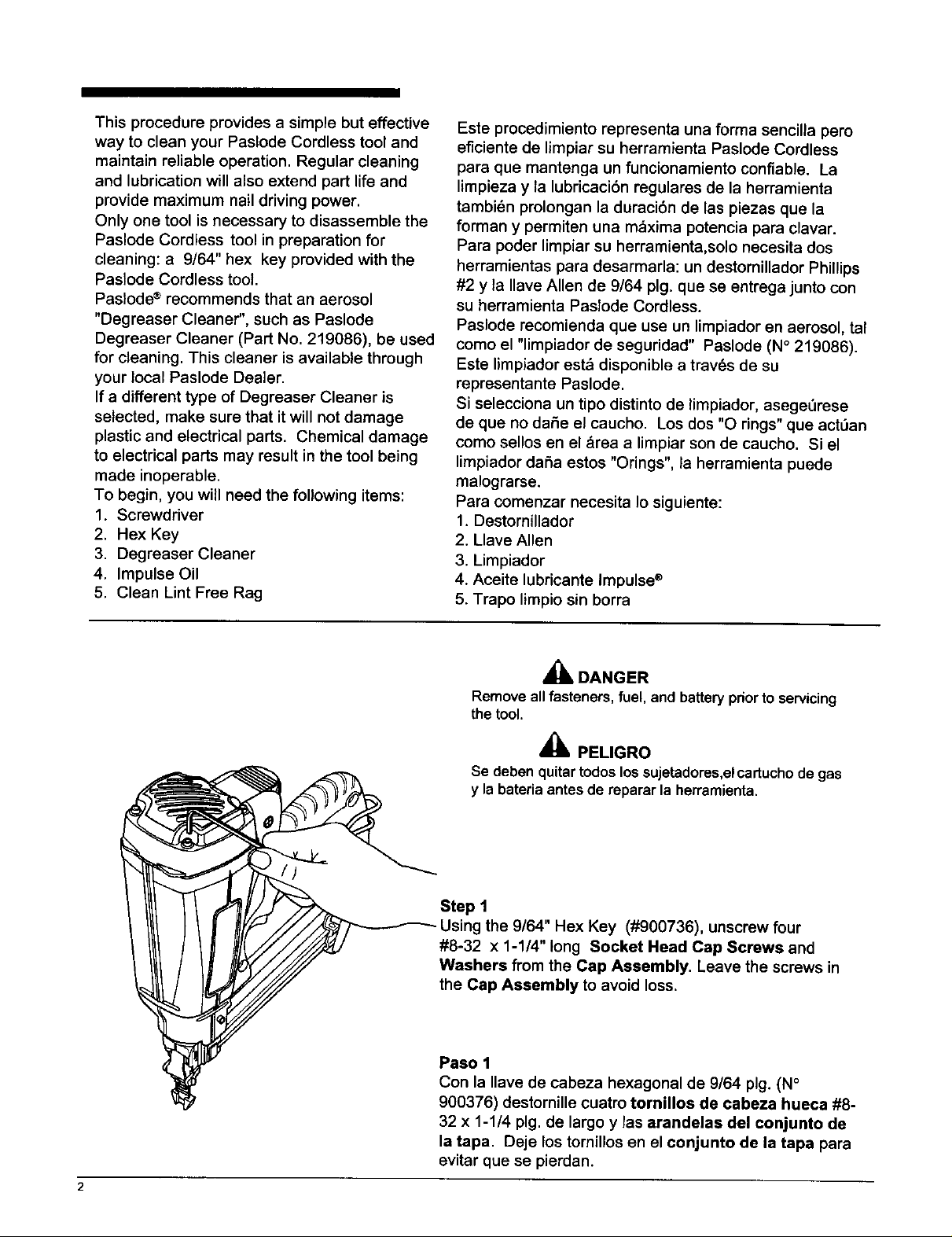
Step 1
Using the 9/64" Hex Key (#900736), unscrew four
#8-32 x 1-1/4" long Socket Head Cap Screws and
Washers from the Cap Assembly. Leave the screws in
the Cap Assembly to avoid loss.
Paso 1
Con la Ilave de cabeza hexagonal de 9/64 pig. (N °
900376) destornille cuatro tornillos de cabeza hueca #8-
32 x 1-1/4 pig. de largo y las arandelas del conjunto de
la tapa. Deje los tornillos en el conjunto de la tapa para
evitar que se pierdan.
Page 3
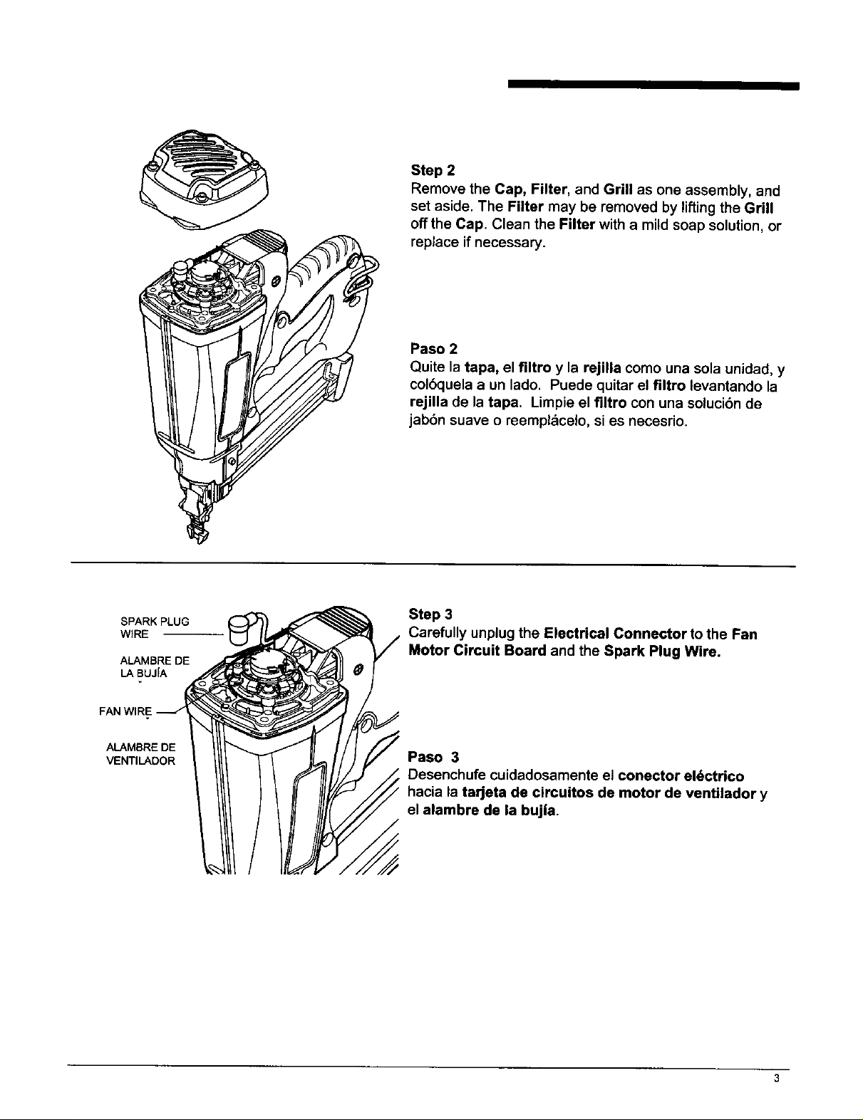
Step 2
Remove the Cap, Filter, and Grill as one assembly, and
set aside. The Filter may be removed by liftingthe Grill
offthe Cap. Clean the Filter with a mild soap solution, or
replace if necessary.
Paso 2
Quite la tapa, el filtro y la rejilla como una sola unidad, y
col6quela a un lado. Puede quitar el filtro levantando la
rejilla de la tapa. Limpie el filtro con una solucibn de
jabbn suave o reempl_celo, si es necesrio.
SPARK PLUG
WIRE
ALAMBRE DE
LA BUJIA
FAN WIRE
ALAMBRE DE
VENTILADOR
Step 3
Carefully unplug the Electrical Connector to the Fan
Motor Circuit Board and the Spark Plug Wire.
Paso 3
Desenchufe cuidadosamente el conector eldctrico
hacia la tarjeta de circuitos de motor de ventilador y
el alambre de la bujia.
Page 4
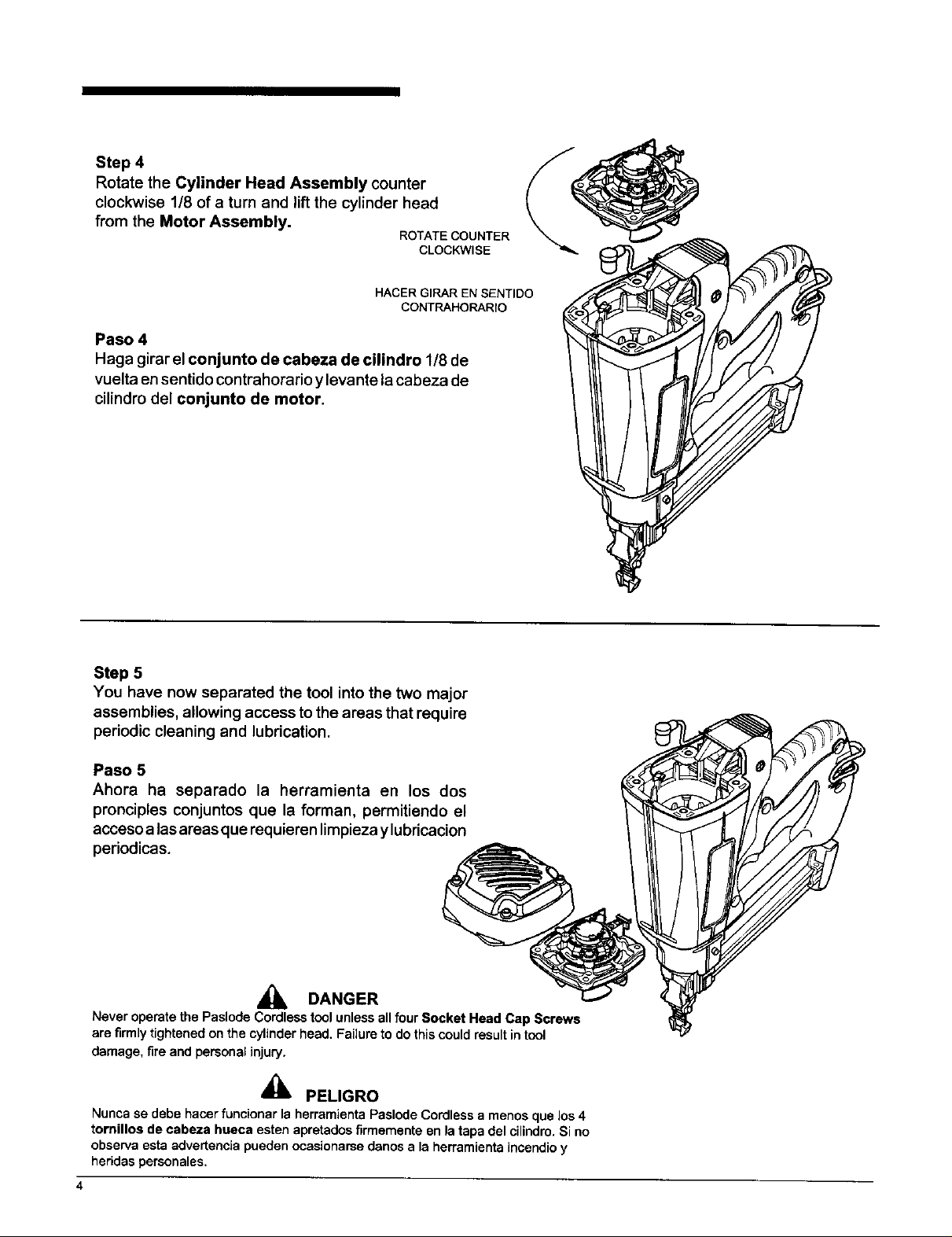
Step4
RotatetheCylinderHeadAssemblycounter
clockwise1/8ofa turnandliftthecylinderhead
from the Motor Assembly.
Paso 4
Haga girar el conjunto de cabeza de cilindro 1/8 de
vuelta en sentido contrahorario y levante lacabeza de
cilindm del conjunto de motor.
ROTATE COUNTER
CLOCKWISE
HACER GIRAR EN SENTIDO
CONTRAHORARIO
Step 5
You have now separated the tool into the two major
assemblies, allowing access to the areas that require
periodic cleaning and lubrication.
Paso 5
Ahora ha separado la herramienta en los dos
pronciples conjuntos que la forman, permitiendo el
acceso alas areas que requieren limpieza y lubricacion
periodicas.
,_ DANGER
NeveroperatethePaslodeCordlesstoolunlessallfourSocketHeadCapScrews
arefirmlytightenedonthecylinderhead.Failuretodothiscouldresultintool
damage,fireandpersonalinjury.
'_ PELIGRO
Nuncase debe hacer funcionar la herramienta Paslode Cordless a menos que los 4
tornillos de cabeza hueca esten apretadosfirmemente en la tapa del cilindro.Si no
observa esta advertencia puedenocasionarse danos a la herramientaincendioy
heridaspersonales.
4
Page 5

Step 6
Spray the Cylinder Head with Degreaser Cleaner. Allow
the dirt and debris to drip off.
Paso 6
Aplique limpiador de seguridad a la tapa del cilindro.
Permita que se escurran la suciedad y los dep6sitos.
Step 7
Using aclean, lint-free rag, wipe offany remaining cleaner
or dirt. Make sure the Seal Rings and Spark Plug are
_ completely clean and clear of debris. Repeat Step 6 to
_ ramove any heavy deposits or remaining residue.
Paso 7
/% / _,_ _ Limpie el limpiador o la suciedad que hayan quedado con
_"_'_f-_T'l l / ! un trapo limpio y sin borra. Aseg_rese de que la bujia de
f_ / U _\ _ encendido y los seal rings est_n completamente limpios
, ' f _ J _1 " \ _' _z_ y sin depbsitos. Repita el paso 6 para eliminar calquier
__,_, \_L,,____ dep6sito o residuo que alanesteen presentes.
5
Page 6

Step 8
Lightly lubricate the Seal Rings with 4-5 drops of
Paslode Impulse ® Oil, part #401482. Make sure
oil is applied evenly around the Seal Rings. Set
the Cylinder Head Assembly aside.
Note: Paslode Impulse Oil is specially formulated
for use in the Paslode Cordless Tool. The use of
other types of lubricants may cause rapid build-up
of combustion residue or result in premature part
failure.
Paso 8
Lubrique ligeramente con 4 a 5 gotas de aceite
lubricante Impulse ®de Paslode, N°401482.
Asegt_rese de aplicar el aceite lubricante de
manera uniforme alrededor del los seal rings.
Coloque el conjunto de la tapa del cilindro a un
lado.
Nora:El aceite lubricante Impulse de Paslode
est& especialmente formulado para usarse con la
herramienta Paslode Cordless. El uso de otros
tipos de lubricantes puede causar una
acumulacfon r_pida de residuos del ala
combustion o la descompostura prematura de las
piezas.
Step 9
Push the Piston Assembly the "down position
using a screwdriver handle or a clean piece of
wood.
Paso 9
Oprima el conjunto del pistbn hasta la posicion
abajo con el mango de un martillo o con pedazo
limpio de madera.
l
Page 7

Step 10
Spray a liberal amount of Degreaser Cleaner into the
inside of the Sleeve and Combustion Chamber.
Invert the Motor Assembly, and let excess cleaner
and dirt drain out.
Paso 10
Aplique una buena cantidad de limpiador de seguridad
dentro della camisa y de la c_mara de combusti6n.
Voltee hacia abajo el conjunto dal motor y permita
que se escurran el exceso de limpiador y la suciedad.
Step 11
Using a clean area of a lint-free rag, wipe off any
remaining cleaner or dirt. Repeat Steps 10 and 11 to
remove any heavy deposits or remaining residue.
Paso 11
Con un trapo limpio y sin borra,limpie el limpiador o la
suciedad que a_n queden. Repita pasos 10 y 11
para quitar cualquier dep6sito o residuo.
Page 8

Step 12
With Motor Assembly tilted up, squeeze 3-4 drops of
Impulse Oil intoSleeve (Area "A")and 4-5 drops onto
lower lip of Combustion Chamber (Area "B") and
apply 4-5 drops around the top of the Combustion
Chamber (area C). Rotate Motor Assembly while
oiling toensure oilis evenly distributed around Sleeve
and Combustion Chamber.
See Tool Cutaway Illustration on page 10.
Note:Donotoveroilthetool.Excessiveoi/ingmaycausestaining
ofworksurface.
Paso 12
Con el conjunto del motor hacia arriba, ponga entre
3 a 4 gotas de aceite lubricante Impulse ® en la
camisa (_rea "A") y de 4 a 5 gotas en el labio inferior
de la c&mara de combustibn (drea "B") y de 4 a 5
gotas alrededor de la parte superior de la cztmara de
combustibn (_rea "C"). Gire el conjunto del motor
mientras aplica la gotas de aceite para asegurase de
que el aceite se distdbuya pot la camisa y lacz_mara
de combustibn. Consulte la ilustracibn del Interior
de la herramienta, en la pdgina 10.
Nota:No devez a poner muchoaceite a dentro la herramienta, Excesivo
aceite puede causar mancha de su trabajosuperficie.
%
Step 13
Hold Motor Assembly upright, and push down and
release several times to allow oil on lower lip of
Combustion Chamber to be evenly distributed.
Paso 13
Sostenga el conjunto del motor hacia arriba; oprima
y suelte varias veces para permitir que el aceite se
distribuye uniformemente pot el labio inferior de la
c=tmara de combustibn.
Page 9

Step14
ManuallypushtheDriverBladeupanddownto
distributetheoilintheSleeveevenly.
Reassemble the Paslode Cordless tool following
disassembly Steps 1-4, pages 2-3 in Reverse order.
Reassembly Note:
Before tightening Cap Screws, depress the nose of
the tool down on itswork contacting element to close
Combustion Chamber. Make sure cylinder head is
centered to the motor, and that the Cap Assembly
does not pinch exposed wires, Cap Screws must be
tightened securely.
Paso 14
Empuje con la mano la hoja del impulsador hacia
arriba y hacia abajo para distribuir el aciete
uniformemente en toda la camisa.
Vuelva a armar la herramienta Paslode Cordless
siguiendo en el orden inverso, los pasos del 1 a 4 en
las paginas 2 a 3.
Nota sobre el rearmado:
Antes de apretar los tornillos de cabeza, presione
hacia abajo la boca de la herramienta sobre el
elemento de contacto de trabajo pare cerrar la
c=tmara de combustibn. AsegOrese de que la
junta t6rica de la cabeza cilindrica estd centrada y
colocada adecuadamente, y que el conjunto de la
tapa no pellizque los cables descubiertos, los
tornillos de cabeza deben estar fuertemente
apretados.
Page 10

ombustion
(C_mara de
combustion)
Sleeve
Piston
"Mid-Check"Area
(Escape)
Motor Assembly
Conjunto del Motor
_k DANGER
Do not attemptto operatethe tool unlessthe cap
assembly is securely attached to the housing.
Operatingthe PaslodeCordless toolwitha loose
or missingcap assemblycan resultinthe escape
of burninggases, tool damage, and injuryto tool
userand property,
Tool
Cutaway
Illustration
NOTE
After the tool is completely reassembled and all
screws are tightened, test the tool for proper
operation. Some smoke may be noticeable from
the exhaust ports on the first few cycles as excess
oil is burned off, Consult the operating manual for
instructions if the tool malfunctions.
_ PELIGRO
No trate de usar la herramienta a menos que el
conjunto de la tapa est6 sujeto firmemente al
bastidor. Si usa la herramienta PaslodeCordless
cuandoe!conjuntodelatapa est_suelto,ocuando
no Io tenga instalado, los gases de combustibn
pueden escapar, la herramientase puede da_ar,
puede cuasar da_os a la propiedady lesionesa
quien lause.
10
NOTA
Despu6s de que hayavuelto a armar completamente
la herramienta y de de que hayaapretado todos los
tornillos,compruebesi la herramientafunciona
correctamente. Es posibleque vea saliralgo de
humode lospuertosde escape durantelosprimeros
ciclos,mientrasse quema el exceso de aceite.
Revise el Manual de Funcionamientoparaconsultar
las intruccionesde averias en la herramienta.
Page 11

Very Dirty • • + _-
Muy sucias • • + +
Dirty " • • • • •
Moderate • • • • • •
Clean • • • •
0 2.5M 5M 7.5M 10M
FastenersDdve_eek
M= 1000 Fasteners
CLEANING INTERVAL
•• Every 2 Weeks
"f" 2-3Days • Monthly
• Weekly • Every 2 Months
The maintenance interval for cleaning the Paslode
IM200 F-18 willvary depending upon the number of
nails driven per week, and the operating conditions
under which the tool is used. When the Paslode
IM200 F-18 is used in a dirtyenvironment or at high
nailing rates for extended periods, cleaning should
be performed at shorter intervals.
Sucias • • • • • •
Moderadas • • • • • •
Limpias • • • •
0 2.5M 5M 7.5M 10M
Sujetadores instalados por semana
M = 1000 sujetadores
INTERVALOS DE LIMPIEZA
•• Cada2 semanas
4" 2-3 Days • Mensualmente
• Weekly • Cada2 meses
El intervalo de mantenimiento para limpiar la clavadora
Paslode IM200F-18 varia dependiendo del n6mero de
clavos instalados por semana y de las condiciones de
operacibn en las que se use la herramienta. Si usa la
clavadora Paslode IM200F-18 en un ambiente sucio o
durante largos perfodos, debe limpiarla a intervalos mas
cortos.
Paslode ®has developed this chart as aguideline to
assist you in establishing the propercleaning sched-
ule for the type of use the tool is getting. If you find
that the suggested cleaning interval is allowing the
tool to become excessively dirty between cleanings,
reduce the interval to the next shorter frequency. If
it is apparent that the Paslode Cordless tool is not
in need of cleaning atthe scheduled time, increase
the interval to the next longer period.
If you have any questions regarding this chart or
any of the instructions in this cleaning procedure,
contact your Paslode distdbutor for assistance.
Paslode desarroll6 esta tabla come unaguia paraayudado
a establecer el programa de limpieze apropiado segOnel
use que le d_ a la herramienta. Si se da cuenta de que el
intervalo de limpieza sugeddo permite que la herramienta
se ensucie demasiado entre las limpiezas programadas,
reduzca el intervalo a lafrecuencia menorsugerida. Si es
aparente que la clavadora Paslode Cordless no necesita
limpieza en el momento sugerido, aumente losintervalos
al siguiente perfodo.
Si tiene alguna pregunta con respecto a esta tabla o a
cualquier instrucci6n en este procedimiento de limpieza,
p6ngase en contacto con su representante de Paslode.
11
Page 12

IM200 F-18 Cleaning Procedure
Printedin U.S.A.
©2001, Illinois Tool Works, Inc.
888 Forest Edge Drive
Vernon Hills, Illinois 60061
www.paslode.com
901071-1
10/01
 Loading...