

Page 1
IMPORTANT!
DO NOT DESTROY
It is the customer's responsibility to have
all operators and service personnel read
and understand this manual.
OPERATING MANUAL
CORDLESS 16 GAUGE STAPLER
Printed in U.S.A.
© 2010 Illinois Tool Works, Inc.
403627-11
04/10
Part No. 900078
www.paslode.com
Page 2
Contents
Introduction and Warranty ............................................... 2
An Overview of the Cordless 16 ga. Stapler ................... 3
Safety Instructions........................................................... 4
Battery and Charger ........................................................ 7
Fuel Cell and Metering Valve .......................................... 9
Preparing the Cordless Stapler for Use ........................ 12
Cordless 16 ga. Stapler Operation ................................ 13
Fasteners and Applications ........................................... 14
Servicing ....................................................................... 15
Troubleshooting ............................................................ 17
egaPtcejbuS
The Paslode battery charger system meets all safety
requirements for power tools.
is a trademark
Paslode
®
An Ilinois Tool Works Company
888 Forest Edge Drive
Vernon Hills, Illinois 60061
Power Nailers are made in the U.S.A.
®
Paslode
is a member of:
Copyright © 2010 Illinois Tool Works, Inc.
1
Page 3

Introduction and Warranty
Paslode Cordless 16 Gauge Stapler
Operating Manual
T
his manual is intended to acquaint you with the Paslode
Cordless 16 ga.Stapler. Unlike other power fastening
tools, the Cordless Stapler is powered by an internal
combustion linear motor. In simpler terms, your Cordless
Stapler is powered by a motor similar to the one that
powers an automobile. The Cordless Stapler ignites a
fuel and air mixture to produce the energy to drive the
motor, which in turn drives the fastener. As you will see,
the Cordless Stapler is totally self-contained. It carries its
own fuel supply and battery, along with a supply of
fasteners.
For ease of use, this manual is divided into sections (see
Contents). Each section of the manual is written with you,
the tooloperator,in mind. We have left out all of the technical
terms so that you can readily understand how to get the
maximum performance from your Cordless Stapler, and
how to avoid damaging the tool or injuring yourself. But, to
accomplish this, we need you to do two things:
1. READ THE MANUAL FROM COVER TO COVER
BEFORE USING THE TOOL.
The Cordless Stapler should be handled like other power
fastening tools that you use. Like most tools, when used
improperly it could result ininjury. If youare going toallow
others to use theCordless Stapler, itis yourresponsibility
to make sure that they also read and comply with the
instructions in this manual before attempting to operate
the tool.
Should you have questions about the Cordless Stapler ,
or wish to obtain additional copies of this manual, please
®
contact your Paslode
representative. The spacebelow is
provided so that you may record your representative's
name, address, and telephone number.
My Paslode representative is:
Name
Address
piZetatSytiC
2. FOLLOW ALL INSTRUCTIONS IN THE MANUAL.
Paslode® Cordless Warranty and Limitations
Paslode warranties that new Cordless power fastening tools,
parts and accessories will be free from defects in material and
workmanship for the period shown below, after the date of
delivery to the original user.
ONE-YEAR LIMITED WARRANTY
A one-year warranty will apply to all parts, except those listed
below as normal wearing parts, or parts which are specifically
covered by an extended warranty.
FIVE-YEAR EXTENDED LIMITED WARRANTY
A five-year warranty will apply to all molded nylon parts:
• Motor Housing, Cap and Grille
• Handle Halves and Actuator
• Trigger
90-DAY LIMITED WARRANTY
A 90-day warranty applies to the following parts, which are
considered normal wear parts:
• Bumper
• Driver Blades
• O-Rings
• Piston Rings
Telephone Number
WARRANTY STATEMENT
This warranty is limited to tools sold and service requested in the
United States. To obtain information on warranty service in the
United States, refer to the Service Center listing that was provided
with your tool.
Paslode's sole liability hereunder will be to replace any part or accessory
whichprovesto be defective within the specific timeperiod. Any replacement
part or accessory provided in accordance with this warranty will carry a
warranty for the balance of the period of warranty applicable to the part it
replaces. This warranty does not apply to part replacement required due
to normal wear.
This warranty is void on any tool which has been subjected to misuse,
abuse,accidental or intentional damage, usewith fasteners,fuel, batteries,
or battery chargers not meeting Paslode specification, size, or quality,
improperly maintained, repaired with other than genuine Paslode
replacement parts, damaged in transit or handling, or which, in Paslode's
opinion, hasbeen altered or repaired in a way that affects or detractsfrom
the performance of the tool.
PASLODE MAKES NO WARRANTY, EXPRESSED
RELATING TO MERCHANTABILITY, FITNESS, OR OTHERWISE,
EXCEPTAS STATED ABOVE, and Paslode's liability ASSTATED ABOVE
AND AS ASSUMED ABOVE is in lieu of allother warranties arising out of,
or in connection with, the use and performance of the tool, except to the
extent other wise provided by applicable law. PASLODE SHALL IN NO
EVENTBELIABLEFORANYDIRECT, INDIRECT, OR CONSEQUENTIAL
DAMAGES, INCLUDING, BUT NOT LIMITED TO, DAMAGES WHICH
MAY ARISE FROM LOSS OF ANTICIPATED PROFITS OR
PRODUCTION, SPOILAGE OF MATERIALS,, INCREASED COST OF
OPERATION, OR OTHERWISE.
Paslode reserves the right to change specifications, equipment, or designs at any time without
notice and without incurring obligation.
OR IMPLIED,
2
Page 4
Overview of the Cordless 16 ga. Stapler
Description
The Paslode Cordless 16 ga. Stapler is a self-contained,
fully portable tool thatuses liquidhydrocarbon fuelto power
a unique linear drive internal combustion motor.
Inorder for you to fully understand the information contained
in this manual, you need a basic understanding of the
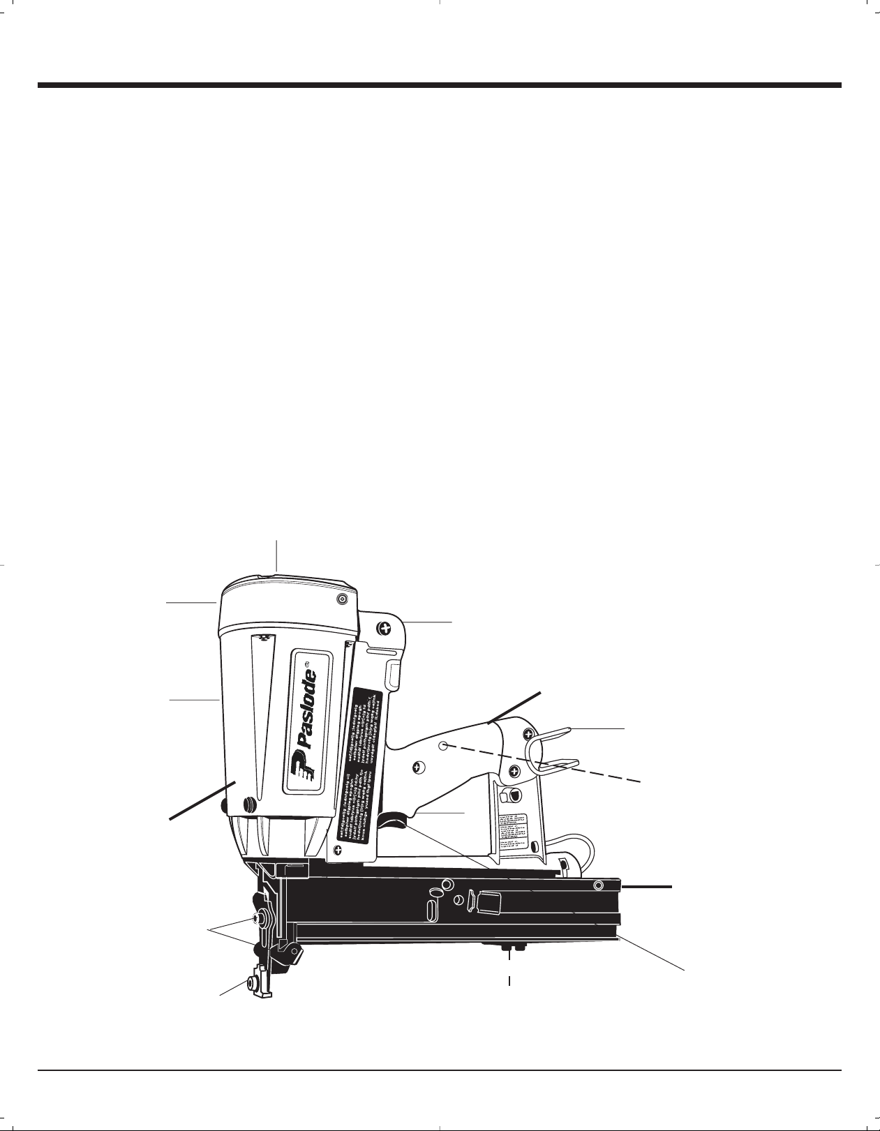
Cordless Stapler. As you can see in the illustration below,
the Cordless Stapler is made up of three separable
assemblies: handle, motor and rail.
As you examine the Cordless Stapler, become familiar with
the three major assemblies and the various components
located in each of them.
The Handle Assembly contains the fuel cell, the battery
indicator light, and the trigger.
The Motor Assembly contains the cover and filter, the
motor housing, the nose, and the work contacting element.
The Rail Assembly contains the components to load and
control the specfic fastener for the Cordless Stapler.
cover & filter
Specifications
Dimensions: Weight 6.5 lbs.
Height 12-1/2 nches
Length 13-1/2 inches
Cycle Rate: Intermittent Operation – 2 to 3 staples
per second
NOTE: Exceeding these rates could cause tool tooverheat,
resulting in loss of performance or damage to tool
components.
By using the Paslode Cordless 16 ga. Stapler at its
recommended cycle rate, you will be able to drive several
thousand nails in a typical workday.
Fasteners: 16 gauge, Std. Crown Staples
Rail Capacity: 2 strips, or 150 fasteners
Battery : 6 volts DC - Provides enough energy to
drive approximately 4000 fasteners ona full
charge.
Fuel Cell: Tallyellow fuelcell (1.32 oz)Part No. 816001
Liquid hydrocarbon - Provides enough fuel
to drive approximately 2400 fasteners.
cap
motor housing
Motor Assembly
Quick Clear
Adjustable
guide
fuel cell compartment
Handle Assembly
belt hook
battery indicator light
(opposite side)
Rail Assembly
follower
trigger
battery compartment
(opposite side)
3
Page 5
Safety Instructions
The following safety instructions have been included in this
booklet to provide you with basic information necessary for
safe operation of the Paslode Cordless 16 ga. Stapler.
WARNING
DO NOT ATTEMPT TO OPERATE THIS TOOL UNTIL
YOU HAVE READ AND UNDERSTAND ALL SAFETY
PRECAUTIONS AND MANUAL INSTRUCTIONS.
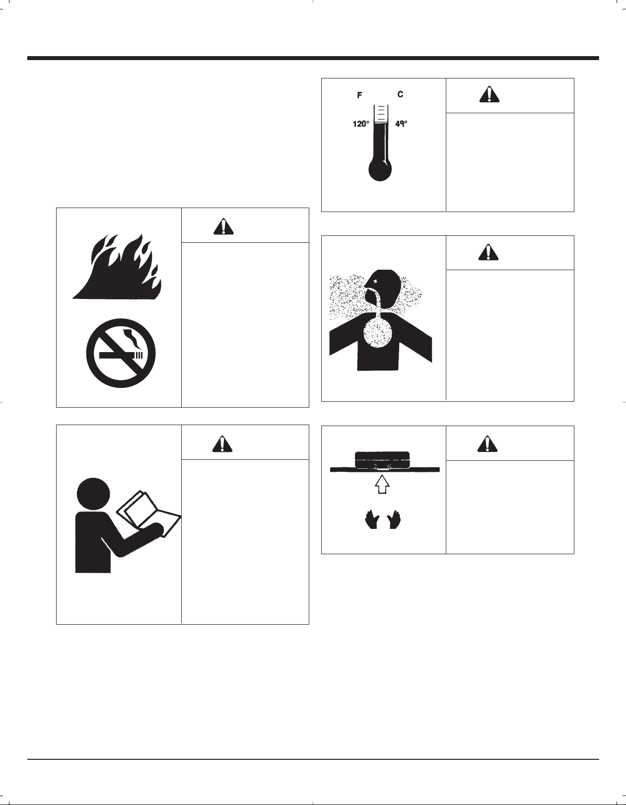
DANGER
The Cordless Stapler is an
internal combustion
device. It produces hot
exhaust gases that may
ignite flammable
materials. This tool must
not be used in a
combustible environment
or in the presence of
combustible materials,
such as flammable
chemicals, adhesives,
gasoline, or solvents.
Do not expose the tool to
temperatures in excess of
120° F (49° C). Fuel and/
or the battery may burst,
releasing flammable gas.
WARNING
This tool must be operated
only in a well-ventilated
environment, because
the tool exhausts carbon
monoxide similar to a gas
chainsaw or lawnmower.
Exposure to carbon
monoxide may cause
dizziness, nausea, or
unconsciousness.
WARNING
Do not attempt to operate
this tool until you have
read and understood all
safety precautions and
manual instructions.
Failure to follow all safety
precautions and
instructions may result in
a permanent loss of vision,
serious personal or even
fatal injury, property
damage and/or tool
damage.
WARNING
ALWAYS keep the
Cordless Stapler, fuel cell,
battery and battery
charger out of the reach
of children.
4
Page 6
WARNING
Safety Instructions
This device helps reduce the possibility of accidental
fastener discharge by preventing the tool from operating
until it is completely against the work surface.
Always wear EYE and
EAR safety gear when
working with or in the
vicinity of the Paslode
Cordless 16 ga. Stapler.
1. Eye protection must meet the requirements of ANSI
Standard Z87.1 and should have side shields for
increased protection.
2. NEVER ASSUME THE TOOL IS EMPTY.
Never point the tool at yourself or anyone else.
3. NEVER ENGAGE IN "HORSEPLAY" WITH THE TOOL.
The Cordless Stapler is not a toy – it is a tool. Careless
and improper use may result in a serious accident.
4. NEVER CARRY THE TOOL WITH YOUR FINGER ON,
OR SQUEEZING, THE TRIGGER.
This practice may result in the accidental discharge of
a fastener.
NEVER operate the tool if the work contacting element
is not working properly.
8. ALWAYS POINT THE TOOL AWAY FROM
YOURSELF AND OTHERS WHEN CLEARING JAMS
OR REMOVING FASTENERS.
Pull the follower slightly back and push the release
lever. Tip the tool nose up slightly and fasteners should
slide out of the rear of the magazine. If fasteners are
jammed, refer to the appropriate servicing section of
this manual.
9. NEVER OPERATE THE CORDLESS STAPLER IF
PARTS ARE LOOSE, DAMAGED OR MISSING.
10. DO NOT DRIVE FASTENERS INTO KNOTS OR ON
TOP OF OTHER FASTENERS.
A fastener may ricochet and cause serious injury.
11. OPERATE THE TOOL ONLY ON THE WORKPIECE.
5. NEVER OPERATE A MALFUNCTIONING TOOL.
Refer to the servicing or troubleshooting section of this
manual to correct the problem. If the problem cannot be
corrected, stop using the tool and report it to your
supervisor or Paslode
6. DO NOT LOAD FASTENERS WITH THE TRIGGER
AND/OR WORK CONTACTING ELEMENT PRESSED
IN.
A fastener may be accidentally discharged.
7. NEVER OPERATE THE TOOL WITH THE WORK
CONTACTING ELEMENT REMOVED OR DISABLED.
®
representative.
WARNING
The Cordless Stapler
should be operated only
when it is in contact with
the work surface. When
fastening thin materials,
be sure to position the tool
so that the fastener is
driven into the underlying
piece.
5
Page 7
Safety Instructions
12. NEVER DRIVE FASTENERS INTO AREAS WITH
CONCEALED HAZARDS.
Always check the area behind the work surface for
electrical wiring, gas pipes, water pipes, sewer drains or
other potential hazards.
13. ALWAYSMAINTAIN SECURE AND UNOBSTRUCTED
FOOTING WHEN ON LADDERS, PLATFORMS OR
OTHER HIGH LOCATIONS.
WARNING
Never over-reach, since
tool recoil may cause a
loss of balance. Always
be aware of edges and
drop-offs when nailing on
rooftops and other high
locations. Keep them in
full view.
14.ALLOW ONLY QUALIFIEDPERSONNEL TO OPERATE
THE CORDLESS STAPLER.
15. PROPERLY STORE FUEL CELL.
WARNING
Always store fuel cells
where they will not be
exposed to an open
flame, sparks or
temperaturesabove 120°
F (49° C).
16. ALWAYS STORE THETOOL WITHTHE FUELCELL
AND BATTERY REMOVED.
Store the fuel cell in the case with the Cordless
Stapler.
17. KEEP THE TOOL CLEAN.
A clean tool is less likely to jam or malfunction.
18. KEEP YOUR HANDS CLEAR OF THE WORK AREA
SURFACE.
WARNING
WARNING
Only persons who have
read and fullyunderstand
all tool operation, safety
and maintenance
instructions should be
allowed to operate the
tool.
Battery Disposal:
The Paslode batteries contain cadmium and must be recycled or disposed of properly. It is illegal in some areas to
place a nickel-cadmium battery into the trash or solid waste stream. You may contact your local recycling center for
information on where to return the spent battery or call 1-800-822-8837 for information on Ni-Cd battery recycling in
your area.
A fastener may exit at an
angle unexpectedly and
cause injury.
6
Page 8
Battery and Charging System
Battery and Charging System
The Paslode Cordless tools come with a rechargeable battery and its own charging system. This
charging system is the only one that will work with
the Paslode batteries (either round or oval). The first
step in preparing a new tool for operation is to fully
charge the battery. New batteries are shipped
discharged and must be charged prior to first
use. Batteries will take 5 minutes to 2 hours (time
will be dependant on the amount of discharge within
the battery) to recharge.
Important Charging Notes
Warning
CHEMICAL/EXPLOSION
HAZARD
Read ALL instructions before charging or using battery. Failure to follow ALL
instructions may result in
fire, severe burns, or release of toxic materials.
Charging Instructions
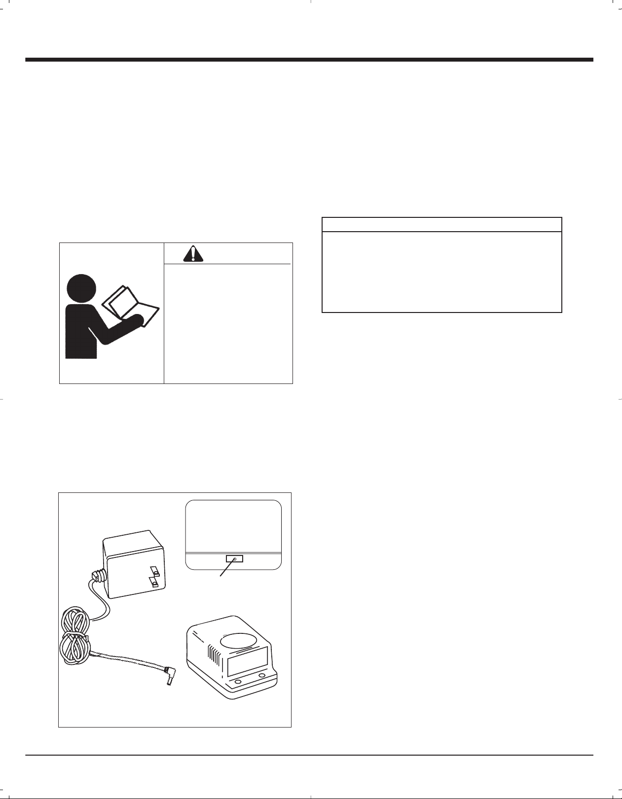
1. Remove wall mount unit with the orange label from
the tool case and plug into a 120V AC outlet. Set
orange charger on a stable surface and insert wall
mount unit’s plug into plug receptacle on the back of
the charger (see picture). A green light indicates
power is on and charger circuit is ready.
2. Remove the battery from tool or case and insert
terminals down into charger. The red light will come
on indicating that the battery is charging and the
green light will go out.
NOTE
If battery is completely discharged, the red and
green lights may flash back and forth for up to 20
minutes. This safety feature slowly recharges the
battery until it is ready to accept the full charging
current. If the red and green light continue to flash
after 20 minutes, replace the battery.
3. After charging is complete, the red light will go out
and the green light will come on, indicating that the
battery is fully charged. The charger will keep the
battery at full charge until it is removed.
Battery Disposal:
The Paslode batteries contain cadmium and must be
recycled or disposed of properly. It is illegal in some
areas to place a nickel-cadmium battery into the trash
or solid waste stream. You may contact your local
recycling center for information on where to return the
spent battery or call 1-800-822-8837 for information on
Ni-Cd battery recycling in your area.
Wall Mount Unit
Plug
THE PASLODE BATTERY CHARGING SYSTEM
REAR VIEW OF
CHARGER BASE
Plug Receptacle
Charger Base
4. Unplug the wall mount unit from the charger and
remove the wall mount unit from the 120V AC outlet.
CHARGING TIMES:
sruoh 2 egrahc tsriF
Discharged Battery 5 minutes to 2 hours
CHARGING DON'TS:
1. Do not charge battery outdoors or in temperatures
below 40°F (5°C).
2. Do not allow metal objects to come in contact with
battery terminals.
3. Do not puncture or attempt to open battery case or
cells.
4. Do not store battery where it will be subjected to
temperatures above 120°F (49°C).
5. Do not incinerate battery.
6. Do not use a defective battery charger, one that
over-heats and/or smokes when plugged in.
7. Do not immerse the battery in water.
Charging System Accessories:
Battery Charger Kit - Part No. 900200
Wall Mount Transformer* - Part No. 900477
Battery Charger Base* - Part No. 900476
Automotive Adapter* - Part No. 900507
* Cannot use with previous (gray in color) charging system
components.
7
Page 9

Battery and Charging System
Inserting Battery
1. Load the battery, contacts first, into the Cordless
Stapler.
2. Align tabs on the battery compartment cover.
Battery Indicator Light
When you insert a fully-charged battery into the tool, you will
see a blinking green light. If the indicator light blinks red,
recharge the battery.
3. Press cover in firmly. Turn cover clockwise to secure.
NOTE: If battery is left in tool for an extended period, the
battery will discharge completely and will require recharging.
8
Page 10
Fuel Cell and Metering Valve
Fuel Cell
DANGER
EXPLOSION/FIRE
HAZARD
Read ALL safety
instructions before using
or handling the fuel cell.
Failure to follow ALL
instructions may result in
explosion or fire. This may
cause severe personal
injuries or property
damage.
Keep the fuel cell away
from heat, sparks and
open flame.
There is a second container inside the fuel cell. The inner
container holds the fuel. The space between the inner
container and the outer cylinder is filled with a gas, called the
propellant, which is under pressure.
To eject the fuel, propellant pressure squeezes the inner
fuel container, much as you squeeze a tube of toothpaste.
This squeezing action ensures that all the fuel is used, and
that the Cordless Stapler can operate in any position.
Because of this container-within-a-container design, you
might hear the sound of fluid when shaking the fuel cell after
all the fuel has been used. This is the propellant, which
remains between the containers even after all the fuel has
been expelled.
If you expose the empty fuel cell to extreme temperatures,
the propellant gas will expand and could cause the container
to burst, releasing flammable gases.
Metering Valve
The metering valve contains a fuel metering system to inject
the correct amount of fuel into the combustion chamber.
Exposure to temperatures
above 120°F (49°C) may
cause the fuel cell to burst,
releasing flammable gas.
WARNING
Sunlight can raise the inside temperature of an
unventilated car or van to above 140°F (60°C).
Never puncture or attempt to open the fuel cell; it is
non-refillable.
Never incinerate, reclaim or recycle the fuel cell.
Never smoke while installing or operating the metering
valve.
Never inhale the spray.
Keep out of the reach of children.
Store fuel cell(s) in well-ventilated areas only.
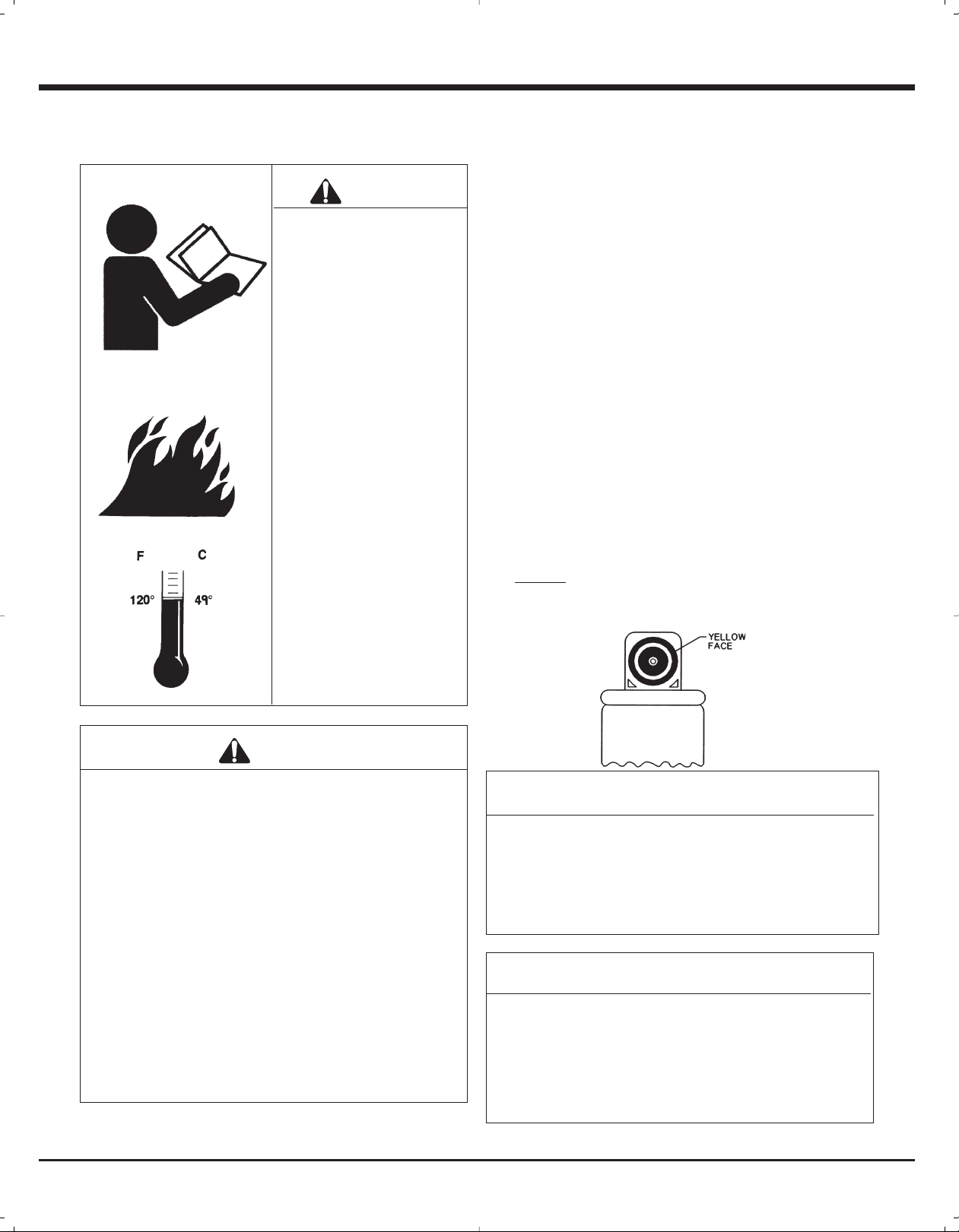
The yellow metering valve is the only valve that will operate
properly with the Cordless 16 ga. Stapler.
NOTE
1. Do not attempt to reuse the metering valve!
Replace with fresh fuel cell/valve, and dispose of
spent cell/valve properly.
2. When replacing fuel cell also clean or replace the
air filter for optimum tool operation.
NOTE: Altitude Restriction
Paslode Cordless tools are powered by an internal
combustion engine and are effected by altitude. The
tool may lose power or not cycle consistently at
elevations of 4000 feet or greater. When using the tool
at elevations of 4000 feet it is recommended to use the
blue high altitude fuel metering valve part #219247.
9
Page 11
Fuel Cell and Metering Valve
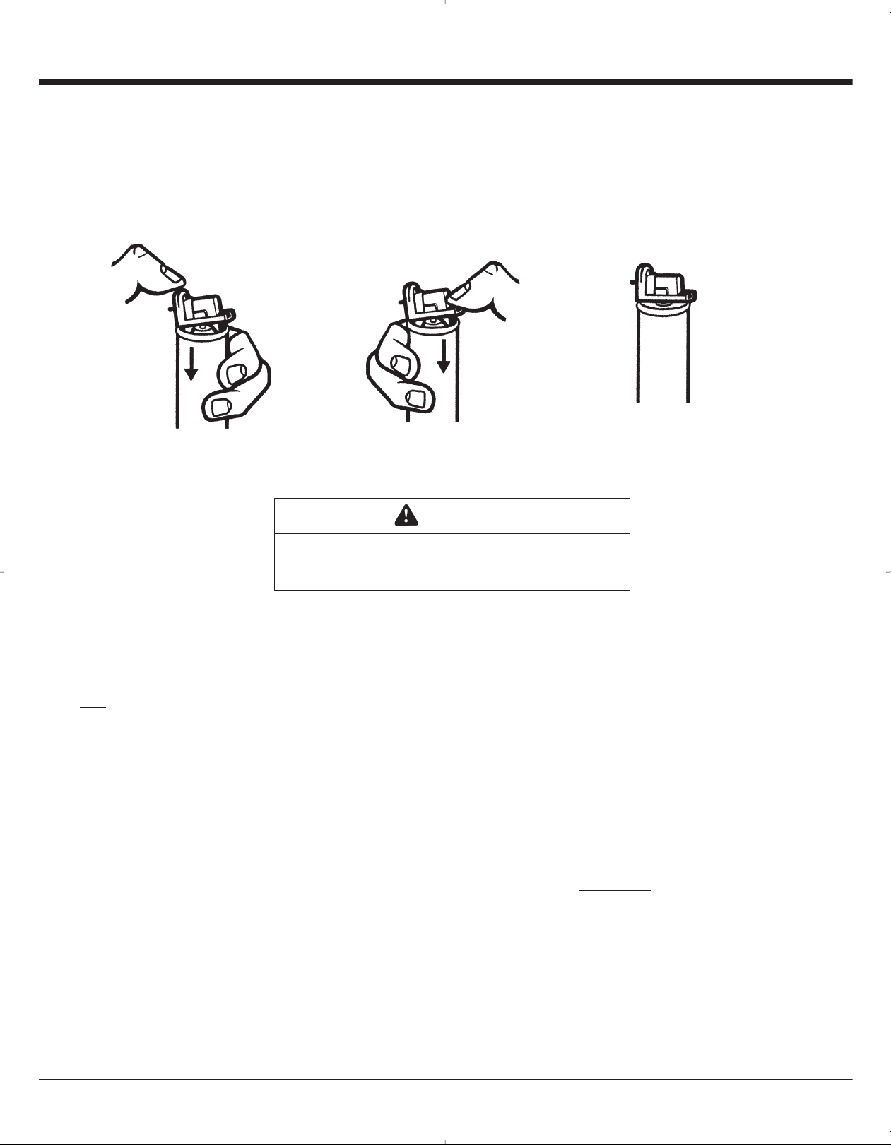
Installing Metering Valve to Fuel Cell Prior to Use
To install the metering valve to a fuel cell:
1. Press downward on the front side of the valve (stem side) until it seats.
2. Press downward on the rear side of the valve until it seats.
3. The valve is now completely seated onto the fuel can and can be inserted into the tool.
.3.2.1
NOTE: Paslode Cordless fuel cells are marked with an expiration date on the bottom of the
can. For maximum performance use fuel before expiration date.
DANGER
Paslode Cordless Fuel Cells are flammable.
Do not smoke when installing the metering valve!
Paslode Cordless Fuel Cell Disposal Guidelines
Paslode the industry leader in cordless technology provides this information to assist users with the proper disposal of discarded
fuel cells. Acceptable disposal options vary depending on the type of fuel cell users. All users must consider federal, state and
local solid waste regulations to ensure that discarded fuel cells are disposed of properly. Users must contact their local solid waste
authority for further guidance.
Discarded fuel cells (used or unused) may be considered hazardous waste under the Resource Conservation and Recovery Act
(RCRA) depending on several factors as described in the paragraphs that follow. Upon disposal used and unused fuel cells may be
classified as ignitable hazardous waste (waste code D001) under U.S. EPA regulations.
Hazardous waste generated by homeowners and contractors who perform routine maintenance for homeowners in their homes are
not regulated by RCRA. In general, "household wastes" generated by homeowners and their contractors are exempt from hazardous waste regulation because those wastes are expressly excluded from the definition of hazardous waste. For example US EPA
has excluded as "houshold waste" aerosol cans that contain residual product and propellent. Thus under federal hazardous waste
regulations homeowners and contractors may dispose of discarded fuel cells as general refuse in a properly permitted municipal
landfill. These users must still contact their local solid waste authority to determine if any state or local regulation prohibits or
restricts such disposal.
Paslode takes no responsibility for proper fuel cell disposal. Proper disposal remains the responsibility of sellers and users. All
sellers and users must contact their local solid waste authority to determine if any federal, state or local regulation prohibits or
restricts disposal. Users may obtain more information about U.S. EPA hazardous waste regulations at the following internet
address: www.epa.gov/epaoswee.osw/hazwaste.htm
Alternatively users may contact U.S. EPA's RCRA Superfund Call Center at 1-800-424-9346 to receive more information.
10
Page 12
Fuel Cell and Metering Valve
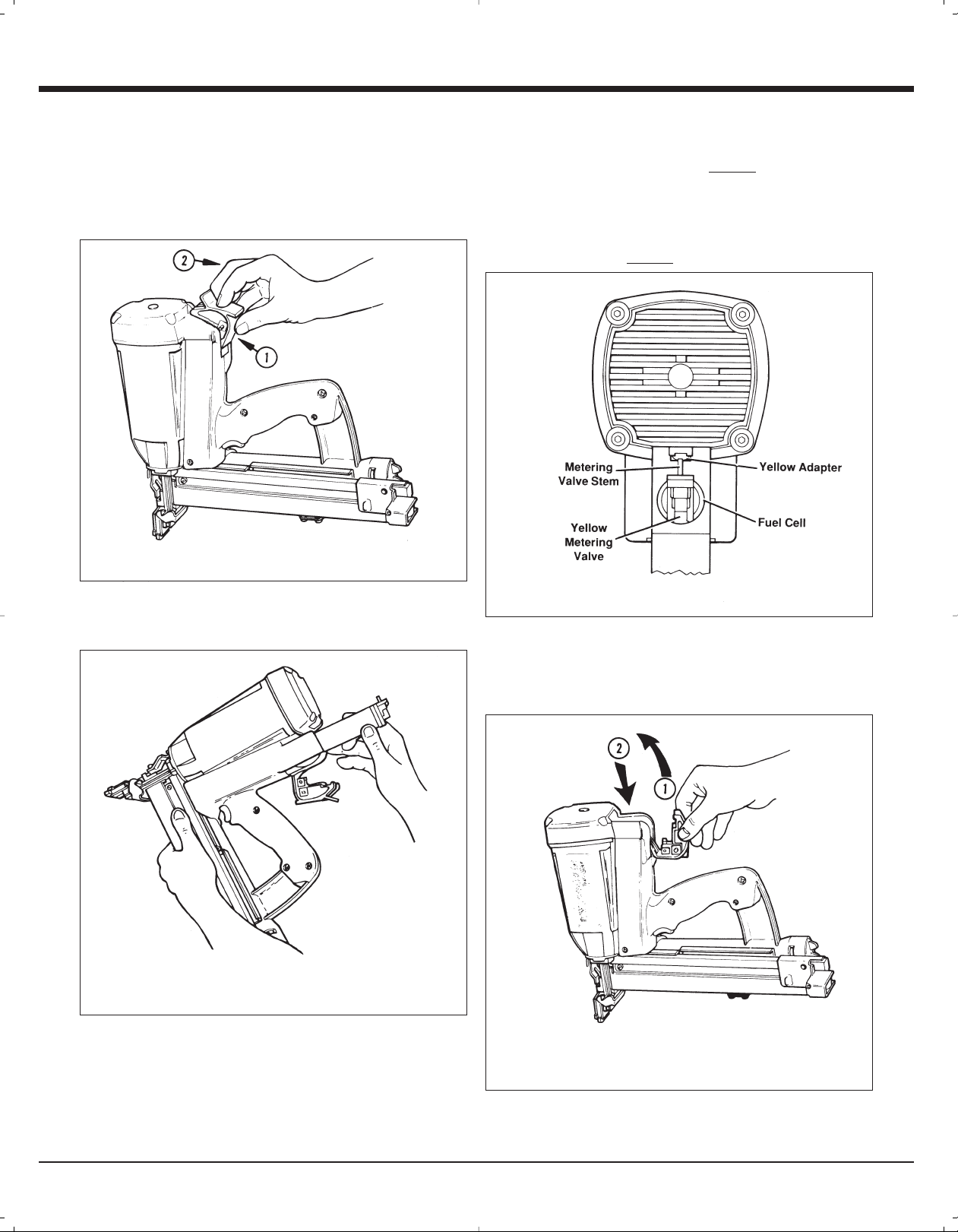
Inserting Fuel Cell
Inserting the metering valve/fuel cell assembly into the
Cordless Stapler is very simple. To begin, press up at the
bottom of the actuator cover and pivot outward to open. The
cover will swing out of the way.
1. PRESS UP
2. PULL OUT
As you slide the metering valve/fuel cell assembly into the
Cordless Stapler, you will notice a
of the cylinder pocket. As shown in the illustration, this
adapter is designed to ensure that the metering valve stem
is properly aligned with the small hole, or orifice, that leads
to the combustion chamber. Insert the metering valve stem
into the orifice of the yellow-colored adapter.
yellow adapter at the top
Next, with the metering valve stem pointed toward the front
of the tool, insert the metering valve/fuel cell assembly.
Close the actuator cover to complete the loading of fuel in
the Cordless Stapler. Do this by swinging it up and over the
fuel valve/cylinder assembly, and pushing down until the
actuator cover snaps into position.
1. SWING UP
2. PUSH DOWN
11
Page 13

Preparing the Cordless 16 ga. Stapler for Use
Fasteners
The Paslode Cordless 16 ga. Stapler drives Paslode
16 ga. staples. They are made from 16-gauge galvinized
wire and are completely coated for improved holding
power. The use of staples that do not meet Paslode
standards could cause tool damage and will void all
warranty claims.
®
Loading Fasteners
When no fasteners are visible, two full strips of Paslode
staples may be loaded. If fasteners are visible, one full
strip may be loaded.
In the illustration above you will see how to properly load
fasteners into the Cordless Stapler. To load:
Cordless 16 ga. Stapler and
Outdoor Weather
Use the Cordless Stapler outdoors, in clear weather,
when the stapler, fuel cell, and battery are between
20°F (-7°C) and 120°F (49°C).
HOT WEATHER OPERATION
The Cordless Stapler requires cooling of the motor
assembly to operate properly. The fan normally
provides the necessary air flow to permit continuous
operation. Whenever the Cordless Stapler is idle for
extended periods, keep the fuel and tool out of direct
sunlight and in surroundings where temperatures will
not exceed 120°F (49°C). After extended periods of
continuous use, it may be necessary to cool the
Impulse motor by setting tool aside for 10-15 minutes
or until the tool operates normally. An overheated tool
may not drive staples completely or may operate
erratically.
COLD WEATHER OPERATION
Fuel cells at cold temperatures lose the required
propellant force. Bring the tool, battery, and fuel cell
above minimum operating temperaturewithout direct
exposure to flame, and check the battery.
1. Draw back the follower until it latches with the follower
latch.
2. Insert one or two strips of Paslode staples onto the rail.
Let them fall forward to the staple guide.
3. Locate thefollower behindthe staples. Release follower
latch. The constant force spring will locate the follower
behind the staples and apply a constant pressure on
them.
Dirtand debrismay interferewith properfeeding offasteners.
Keep the fastener track clean.
CAUTION
The Cordless Staplershould notbe usedin therain
or where excessive moisture is present. The use of
the Cordless Stapler under these conditions may
result in damage totool components and cause tool
to malfunction.
CAUTION
This tool must be operated in a well ventilated
environment, because the tool exhausts carbon
monoxide similar to a chainsaw or lawn mower.
Exposureto carbon monoxide may cause dizziness,
nausea or unconsciousness.
12
Page 14

2
PRESS WORK –
CONTACTING
ELEMENT
AGAINST THE
WORK SURFACE.
Fan motor starts,
fuel is injected into
combustion
chamber and
mixed with air by
the fan.
SQUEEZE
TRIGGER
Spark plug sparks
and fuel/air mixture
ignites.
Combustion
powers piston
assembly driving
fastener.
LIFT TOOL RELEASE
TRIGGER
Combustion
chamber opens.
Fan exhausts hot
gases and cools
internal
components.
Cordless 16 ga. Stapler Operation
Work
Contacting
Element
Hex Nut
Depth of Drive Adjustment
Remove the battery before adjusting thedepth of drive.
The depth of drive adjustment is made by simply loosening
the 3/8" hex nut, adjusting todesired depth and retightening
the hex nut.
Dual Function of the Work Contacting
Element:
The Cordless Stapler has the unique feature of a dual
function contacting element.
For Siding Applications:
Loosen the 3/8" hex nut and adjust the work contacting
element up or down for staple standing height.
picture)
For Sheathing Applications:
Remove the 3/8" hexnut.
Remove the work contacting element.
Turn the work contacting element upside down
Replace the washer and tighten the hex nut down.
(see above
DANGER
The work contacting element and nose will become hot
after prolonged or rapid use. If it becomes necessary to
adjust the work contacting element, avoid touching with
bare hands.
NOTE
The Cordless stapler will "blank fire" or cycle even if
the magazine is empty of nails. Blank firing will
create driver blade marks on the workpiece, and
excessive impact on the bumper which may result in
premature failure of the bumper.Therefore, load the
Cordless Stapler when required and only cycle it
when staples are in place.
13
Page 15

Fasteners and Applications
Fasteners
The Paslode Cordless 16 ga. Stapler drives Paslode 16 ga.
Series staples. They are made from 16-gauge galvanized
wire and are entirely coated, for improved holding. Fasteners
are collated into strips of 75 for easy loading.
Applications
Vinyl Siding
Vinyl Clad Steel
Light Decking
0T5240 GS-16 3/4" (12.00 x 19.05) C Galv.
400026 GS-16 1" (12.00 x 25.40) C Brite
0T5242 GS-16 1" (12.00 x 25.40) C Galv.
Remodeling
Soffits
ELPATSNOITPIRCSED.ON TRAP
0T5243 GS-16 1-1/8" (12.00 x 29.00) C Galv.
400027 GS-16 1-1/4" (12.00 x 31.75) C Brite
0T5238 GS-16 1-1/4" (12.00 x 31.75) C Galv.
400028 GS-16 1-1/2" (12.00 x 38.10) C Brite
0T2695 GS-16 1-1/2" (12.00 x 38.10) C Galv.
400029 GS-16 1-3/4" (12.00 x 44.45) C Brite
0T2250 GS-16 1-3/4" (12.00 x 44.45) C Galv.
400030 GS-16 2" (12.00 x 50.80) C Brite
0T2258 GS-16 2" (12.00 x 50.80) C Galv.
14
Page 16

Servicing
Restrict Field Service to the Following
CHECKING THE ENERGY LEVEL OF THE BATTERY
RECHARGING THE BATTERY
CHECKING THE FUEL CELL AND METERING VALVE
REPLACING THE FUEL CELL
CLEANING THE AIR FILTER
CLEARING A JAM
CLEANING THE TOOL (See cleaning manual)
Attempts to go beyond these procedures could result in
serious personal injury or damage to the Cordless Stapler
and voiding the warranty.
There are certain problems you may encounter when you
are using the Cordless Stapler that you will be able to correct
on the work site. The following field service procedures are
the only service procedures you should attempt. Anything
else that may appear wrong with the Cordless Stapler
should only be diagnosed and repaired by a fully trained
service technician. If you have any reason to believe that
your problem is beyond the service procedures in this
manual, contact your Paslode
DANGER
Never attempt any maintenance of the Paslode Cordless
tool without first removing the fuel cell and battery.
Maintenance should be started only after the tool is
completely inoperative.
®
representative immediately.
Battery Check
Periodically check on the battery indicator light - (the light
in the handle) of the Cordless Stapler. When encountering
a problem, the first step should always be to make sure the
battery has enough energy to operate the tool.
Fuel Cell Check
If the Cordless Stapler's fan operates and the indicator light
is green, but the tool will not cycle or does not drive
fasteners completely, check the fuel cell. With the fuel cell
out of the tool, check to see if the cell still contains fuel and
that the metering valve is working. To determine if there is
any fuel left in the fuel cell, hold in the upright position and
simply place the metering stem against a solid object, and
gently push about three or four times. A small amount of fuel
should be released each time.
DANGER
Wear safety glasses when performing this test. Never
perform this test near an open flame or sparks, while
smoking, or where the fuel may get into your eyes.
If fuel is not released with each operating of the metering
valve, this indicates that there is no more fuel left in the
cylinder and it must be replaced. Dispose of the empty fuel
cell properly.
Clearing a Jam
A typical problem you may encounter is having a jammed
fastener. Because of the unique design of the Cordless
Stapler, clearing a jammed fastener is easy:
1. Remove the battery.
2. Pull follower back until it latches with rail cover.
3. Push latch, releasing front guide. Pivot front guide
forward.
4. Clear jam, and push driver blade back up to its normal
position.
5. Close front guide and latch it. Check that work contacting
element is free.
6. Release follower.
When the work contacting element is depressed on work
piece, the fan motor will turn on and the blinking green
indicator light will turn solid green. If the indicator light blinks
red or glows red, recharge the battery.
15
Page 17

Servicing
Clearing a Jam (continued)
Make certain magazine mounting screws are tight and
magazine is tight to nose. Attemptingto fire tool withaloose
magazine will result in loss of staple control, damage to tool,
or staple discharge toward operator.
Air Filter
Open the cover by pressing slightly above the yellow
adapter, and pivoting the cover open. The air filter simply
lifts out.
Tap the filter GENTLY to remove any dust. Check and clean
the air filter every two days. Soap and water restores the
filter to a "like new" condition.
When you get home:
1. Place the battery in its charger if it needs charging as
indicated by the red charge light on the handle.
2. Wipe your Cordless Stapler with a clean, soft cloth.
3. Remove and clean the filter every two days.
4. Check work contacting element to ensure it is operating
freely.
Paslode Cordless Tool Accessories
A variety of accessories are available for the Paslode
Corldess Stapler:
Battery - Part No. 402500
Clear Safety Glasses - Part No. 401382
Paslode Cordless Lubricating Oil - Part No. 401482
Battery Charger Kit - Part No. 900200
End-of-Workday Routine
These simple stepsare based on maintainingthe safety and
operational efficiency of the Cordless Stapler.
Before you leave the work site:
1. Remove battery and store in tool case. Always use the
Cordless Stapler case for transporting and storing the
tool.
Paslode Cordless Stapler Carrying Case - Part No.
900362
Degreaser Cleaner - Part No. 219086
Automotive Adapter - Part No. 900507
®
Contact your Paslode
information.
representative for additional
Tools
A 5/32 Hex Wrench (Part No. 401331)is provided with
each Cordless 16 Gauge Stapler.
2. Dispose of all empty fuel cells. Remember to dispose of
these cells where they will not be crushed, punctured,
burned or found by children.
16
Page 18

Troubleshooting
Preparing Tool for Operation - Battery/Charger Problems
Battery does not appear to accept charge
when battery is plugged into the charger.
Inoperative indicator lights on charger, or
defective charger.
Try battery in tool after a full charge cycle.
If tools indicator light is green, charger not
working properly. Replace charger, or
monitor charging time to ensure battery has
adequate time for recharging. It is normal
for battery to feel warm after properly
charging.
ECIVRESSMELBORP ELBISSOPMOTPMYS
Charger gets hot, makes excessively loud
noise, or smokes during charging cycle.
Charger cord or wall plug gets hot.
Normal Stage of Operation
Fan does not run - tool indicator light is
blinking red or solid red.
Fan does not run, or runs slower than
normal - tool indicator light is solid red.
Work-contacting element does not depress
fully - tool does not oeprate.
Tool will not cycle - fan runs, indicator light
is solid green.
Battery damaged or cycle life exhausted.
Damaged charger.
Battery is not charged.
Battery terminals are oily, dirty, or corroded.
Battery is discharged.
Work-contacting element is bent, or build-up of
debris in track restricts operation.
Fuel Cell empty.
Spark wire out of spark plug.
Spark plug is dirty.
No spark is generated.
Replace battery.
Discontinue use immediately and unplug
from power source. Replace charger and
tag or dispose of charger to prevent
accidental re-use or connection to power
source.
ECIVRESSMELBORP ELBISSOPMOTPMYS
Charge battery.
Clean battery terminals with soft cloth.
Charge battery.
Remove and inspect lower probe. Clean the
track. Repair or replace lower probe as
required.
Replace fuel cell.
Remove cap and check spark lead, insert in
spark plug and replace cover.
Clean tool cylinder head.
®
Return tool to authorized Paslode
service.
dealer for
17
Page 19

Troubleshooting
Normal Stage of Operation
ECIVRESSMELBORPELBISSOPMOTPMYS
Tool operates properly, but fasteners do not
drive fully.
Tool operates properly, but fasteners are
sometimes over-driven, and sometimes
under-driven.
Tool operates, but no fastener is driven.
Tool operates erratically or appears to be
losing power - tool indicator light is green.
Work-contacting element requires adjustment.
Fuel cell is low.
There may be loss of seal in combustion
chamber.
Work-contacting element is not adjusted
properly for the type of material being
fastened.
Wrong fasteners being used.
Follower not properly engaged behind fastener
strip.
Jammed fastener.
Fuel cell is low.
Spark plug wire is loose.
Filter element is dirty, causing tool to overheat.
Adjust work contacting element.
Check fuel cell and replace as required.
Press work contacting element against
workpiece for one minute. Pull trigger. If
fastener does not drive, there is a leak that
requires service.
Adjust work-contacting element. Readjust
as required when material density or
thickness of material being fastened
changes.
Use only fasteners meeting Paslode
specifications. Check Fasteners and
Applications section for fastener types and
sizes recommended for use in Impulse tool.
Position follower behind fastener strip and
engage strip.
Clear jam.
Check fuel cell.
Check spark plug wire.
Remove filter element and clean. Use soap
and water to remove stubborn debris.
®
Clean tool.
Clean driver blade and nose bore with
degreaser cleaner.
Return tool to authorized Paslode® dealer
for service.
Clean tool.
Clean track or replace work-contacting
element.
Tool operated and drove fasteners, but
driver blade did not return to up position.
Combustion chamber does not drop after
tool cycles.
Tool sleeve or O-rings are dirty.
Built-up dirt and debris on driver blade or in
nose bore.
Mid check is dirty or disabled.
Tool (sleeve) or O-rings are dirty.
Work-contacting element is bent, or is dirty.
If tool will not operate after following the above service directions, return the tool to an
authorized Paslode.® representative for service.
For the nearest Paslode® representative call 1-800-682-3428.
For factory direct service call 1-800-447-3830.
For Tec hnical support call 1-800-222-6990 or visit our web site at www.paslode.com.
To purchase parts, visit our website at www.itwconstructionparts.com
18
Page 20

18
www.itwconstructionparts.com.
Para comprar las partes, visite nuestro sitio del web en partes de
www.paslode.com.
Para llamada técnica de apoyo 1-800-222-6990, o visita nuestro sitio web en
Para la fábrica dirige el servicio la llamada 1-800-447-3830.
Para un represente de Paslode, llame a 1-800-682-3428.
devuelva la herramienta a su representante Paslode® para que reciba servicio.
Si la herramienta no funciona después de seguir las instrucciones de servicio,
contacto.
Limpie el carril o cambie el elemento de
Limpie la grapadora.
para que reciba servicio.
Envíe la grapadora a su proveedor Paslode
punta con un limpiador desengranaste.
Limpie la hoja del impulsor y el orificio de la
Limpie la herramienta.
para limpiar la suciedad difícil de quitar.
Quite el filtro y límpielo. Use agua y jabón
Revise el cable de la bujía..
Revise el cartucho de gas.
Saque las grapas atorados.
grapas y sujételo.
Coloque el transportador detrás de la tira de
esta grapadora Impulse.
ver los tipos y tamaños recomendados en
sección de Sujetadores y aplicaciones para
especificaciones de Paslode. Revise la
Use sólo clavos que cumplan con las
siendo clavado.
la densidad o el espesordelmaterialque está
ajustar según sea necesario cuando cambie
Ajuste el elemento de contacto. Vuelva a
que debe ser reparada.
el gatillo. Si la grapa no sale, hay una fuga
pieza de trabajo durante un minuto. Oprima
Presione el elemento de contacto contra la
necesario.
Revise el cartucho de gas y cámbielo si es
Ajuste el elemento de contacto.
está sucio.
El elemento de contacto está doblado o el carril
sucios.
La camisa de la grapadora o los anillos O están
deshabilitada.
La sección interior de la clavadora está sucia o
o en el orificio de la punta de la grapadora.
Sehaacumuladosuciedad en la hoja del impulsor
están sucios.
La camisa de la herramienta o los anillos en “O”
la grapadora.
El filtro está sucio, y hace que se sobrecaliente
El cable de la bujía está suelto.
bajo.
El nivel de combustible cartucho de gas está
La grapadora tiene grapas atoradas.
la tira de grapas.
El transportador no está bien ajustado detrás de
Está usando grapas incorrectos.
tipo de material que está siendo clavado.
El elemento decontacto no estábien ajustado al
Puede haber fugasenla cámara decombustión.
bajo.
El nivel de combustible cartucho de gas está
Es necesario ajustar el elemento de contacto.
SÍNTOMA POSIBLES PROBLEMAS SERVICIO
que funciona la grapadora.
La cámara decombustión nobaja después de
superior.
la hoja del impulsor no volvió a la posición
La grapadora funcionó y clavó la grapa, pero
grapadora está verde.
perder potencia - la luz indicadora de la
Lagrapadora funciona erráticamente o parece
grapas.
La grapadora funciona pero no dispara las
veces no penetran lo suficiente.
las grapas a veces penetran demasiado y a
La grapadora funciona correctamente, pero
las grapas no penetran por completo.
La grapadora funciona correctamente, pero
Durante el funcionamiento normal
Detección y corrección de fallas
Page 21

17
Paslode para que la repare.
Envíe la grapadora a su distribuidor autorizado
No se producen chispas.
Limpie la culata del cilindro de la grapadora.
bujía y vuelva a colocar la cubierta.
Quite la cubierta y revise la bujía, coloque la
Cambie el cartucho de gas.
carril. Repare o cambie el probador inferior.
Quite y revise el probador inferior. Limpie el
Cargue la batería.
corrosión o están sucias.
Las terminales de la batería tienen grasa,
Cargue la batería.
La bujía está sucia.
a la bujía.
El cable que produce la chispa no está conectado
El cartucho de gas está vacío.
funcionamiento.
acumulación de suciedad restringe su
El elemento de contacto está doblado, o la
La batería está descargada.
de esmeril fina.
Limpie las terminales de la batería con una tela
La batería no está cargada.
SÍNTOMA OICIVRESSAMELBORP SELBISOP
constantemente en verde.
funciona. La luz indicadora está iluminada
La grapadora no clava, pero el ventilador sí
por completo - la grapadora no funciona.
El elemento de contacto no se puede oprimir
en rojo.
la clavadora está iluminada constantemente
lentamente de lo normal - la luz indicadora de
El ventilador no funciona, o funciona más
o parpadeando en rojo.
la grapadora está iluminada constantemente
El ventilador no funciona - la luz indicadora de
conecte accidentalmente o lo vuelva a usar.
cargador defectuoso para evitar que alguien lo
el cargador y coloque una etiqueta en el
desconéctelo de la fuente de energía. Cambie
Deje de usar el cargador de inmediato y
Obtenga una batería nueva.
correctamente.
tibia después de haberla cargado
recargarse. Es normal que la batería se sienta
que la batería tenga el tiempo adecuado para
o regule el tiempo de carga para asegurarse de
funcionando debidamente. Cambie el cargador
clavadora está verde, el cargador no está
de un ciclo de carga. Si la luz indicadora de la
Pruebe la batería en la herramienta después
Detección y corrección de fallas
El cargador está dañado.
ciclo de vida.
La batería está dañada o se ha terminado su
funcionan, o el cargador está defectuoso.
Las luces indicadoras en el cargador no
SÍNTOMA OICIVRESSAMELBORP SELBISOP
Durante el funcionamiento normal
se calientan.
cable del cargador o el transformador de pared
o produce humo durante el ciclo de carga. El
El cargador se calienta, hace demasiado ruido
horas.
la batería está conectada en el cargador de 3
el cargador se conecta a la batería o cuando
La batería no parece aceptar la carga cuando
Preparación de la grapadora antes de usarla - Problemas con la batería o con el cargador
Page 22

nal de 9/64 plg (pieza No. 401331).
Cada grapadora viene acompañada de una llave hexago-
Herrmientas Paslode
16
o quemados.
los niños y dondeno puedan ser aplastados, perforados
que debe desecharlos donde no los puedan encontrar
2. Deseche todos los cartuchos de gas vacíos. Recuerde
transportarla y almacenarla.
Siempre use el maletín de la grapadora para
1. Quite la batería y guárdela en el maletín de la clavadora.
su representante de Paslode®.
Para obtener mayor información póngase en contactocon
Limpiador - Pieza No. 219086
Maletín - Pieza No. 900362
Adaptor para Automobile - Pieza No. 900507
Juego de cargador de baterías - Pieza No. 900200
Aceite Lubricante de Paslode - Pieza No. 401482
Lentes de seguridad claros - Pieza No. 401382
Batería - Pieza No. 402500
la grapadora Paslode:
Existe una gran variedad de accesorios disponibles para
Accesorios
que funciona sin obstrucciones.
4. Revise el elemento de contacto para asegurarse de
3. Saque y limpie el filtro cada dos días.
suave.
2. Limpie la grapadora Paslode con un paño limpio y
ser recargada colóquela en el cargador.
1. Si la luzroja en el mango indica que la batería necesita
conector
Alambre de
terminal
Tornillo de
Chispa de alambre
Tapa
cabeza hexagonal
Llave allen de
Filtro
Cubierta
Antes de salir de su lugar de trabajo:
grapadora Paslode.
pasos para mantener la seguridad y la eficiencia de la
Al final de cada día de trabajo lleve a cabo estos sencillos
Rutina al final de un día de trabajo
de agua y jabón deja el filtro como “nuevo”.
Reviseylimpie el filtro de aire cada dos días. Una solución
Golpee LIGERAMENTE el filtro para sacarle el polvo.
simplemente sale hacia fuera.
y pivoteando la cubierta para que se abra. El filtro de aire
Abralacubierta oprimiendo ligeramente arribadel adaptador,
Cuando llegue a casa:
Filtro de aire
Servicio
Page 23

15
Transportador
(vea la pagina 16.)
PELIGRO
frente
guía de
6. Suelte el transportador.
5. Cerre la guía de frente y el picaporte.
el puesto normal.
4. Clara clavos atorados, empuje el pistón para atrás del
la guía de frente para adelante.
3. Empuje el picaporte, libertando la guía de frente. Pivote
cubierta del riel.
2. Tire el transportador hasta que quede asegurado con la
1. Saque la batería.
Impulse, es muy sencillo sacar los clavos atorados:
con clavos atorados. Debido al diseño único de la grapadora
Un problema típico que puede encontrar es una grapadora
PELIGRO
Para desatorar la grapadora
gas vacío de forma adecuada.
y que debe reemplazar el cartucho. Deseche el cartucho de
válvula, significa que no hay más combustible en el cilindro
Si no sale combustible cada vez que active la aguja de la
pueda entrar en los ojos.
de chispas, mientras fuma, o donde el combustible le
Nunca lleve a cabo esta prueba cerca de una llama o
Use los lentes de seguridad cuando haga este prueba.
bustible.
vez que oprima debe salir una pequeña cantidad de comun objeto sólido y oprima unas tres a cuatro veces. Cada
vertical y simplemente coloque la aguja dosificadora contra
si queda combustible en el cartucho, sosténgalo en posición
y si la válvula dosificadora está funcionando. Para comprobar
la grapadora, revíselo para ver si aún contiene combustible
cartucho de gas. Cuando el cartucho de gas esté fuera de
dispara o no clava por completo las grapas, revise el
indicadora está iluminada en verde, pero la grapadora no
Si funciona el ventilador de la grapadora Paslode y la luz
continua, recargue la batería.
indicadora se enciende en rojo, en forma parpadeante o
parpadeante se ilumina en forma constante. Si la luz
de trabajo, arranca el motor del ventilador y la luz verde
Cuando se presiona el elemento de contacto contra la pieza
energía para hacer funcionar la grapadora.
ser siempre asegurarse de que la batería tenga suficiente
Impulse. Cuando tenga un problema, el primer paso debe
decir, la luz indicadora en el mango de la grapadora
Revise periódicamente la luz indicadora de la batería, es
Revisión de la batería
inoperable.
después de que la grapadora esté completamente
y la batería. El mantenimiento sólo debe hacerse
grapadora Impulse sin antes quitar el cartucho de gas
Nunca intente hacer trabajos de mantenimiento en la
representante de Paslode.
póngase en contacto inmediatamente con su
con los procedimientos de servicio de este manual,
considera que su problema es más difícil de corregir que
y reparado por un técnico de servicio entrenado. Si
que tenga su grapadora Paslode debe ser diagnosticado
intentar realizar por sí mismo. Cualquier otro problema
procedimientos de servicio son los únicos que debe
corregir en el lugar de trabajo. Los siguientes
al usar su grapadora Paslode, que usted mismo puede
Existen ciertos problemas a los que se puede enfrentar
o causar daños a la grapadora y anular la garantía.
estos procedimientos, puede llegar a sufrir lesiones graves
Si intenta efectuar reparaciones mayores a las que indican
LIMPIAR LA HERRAMIENTA
DESATORAR LA GRAPADORA
LIMPIAR EL FILTRO DE AIRE
REEMPLAZAR EL CARTUCHO DE GAS
DOSIFICADORA
REVISAR EL CARTUCHO DE GAS Y LA VÁLVULA
RECARGAR LA BATERIA
REVISAR EL NIVEL DE ENERGIA DE LA BATERIA
Servicio
Revisión del cartucho de gas
En el lugar de trabajo limítese a:
Page 24

14
0T2258 GS-16 2" (12.00 x 50.80) C Galv.
400030 GS-16 2" (12.00 x 50.80) C Brite
0T2250 GS-16 1-3/4" (12.00 x 44.45) C Galv.
400029 GS-16 1-3/4" (12.00 x 44.45) C Brite
0T2695 GS-16 1-1/2" (12.00 x 38.10) C Galv.
RODATEJUSNOICPIRCSED.ON AZEIP
400028 GS-16 1-1/2" (12.00 x 38.10) C Brite
0T5238 GS-16 1-1/4" (12.00 x 31.75) C Galv.
400027 GS-16 1-1/4" (12.00 x 31.75) C Brite
0T5243 GS-16 1-1/8" (12.00 x 29.00) C Galv.
0T5242 GS-16 1" (12.00 x 25.40) C Galv.
400026 GS-16 1" (12.00 x 25.40) C Brite
0T5240 GS-16 3/4" (12.00 x 19.05) C Galv.
Plataformas
Remodelando
Entablados ligero
Apartadero de Clad acero
Apartadero de vinyl
Aplicaciones
cotejarado dentro de una tira de 75 para cargar facil.
capa para mejorar la fuerza. Sujetadores estan
hecho de calibre 16 glavanizado alambre Y estan todo
La grapadora Paslode clava S16 serie grapas. Estan
Sujetadores
Sujetadores y Aplicaciones
Page 25

13
hexagonal
cabeza
nuez de
Contacto
de
Elemento
los clavos estén en su lugar
cuando sea necesario y hacerla funcionar sólo cuando
tanto,se debe cargarla clavadora paraacabados Impulse
provocando una falla prematura en el mismo. Por lo
trabajoyse producíra un fuerteimpacto en el amortiguador,
ese caso, lashojas delimpulsador rayarán el material de
cuando el mecanismo de alimentacíon esté vacío. En
La grapadora puede"disparar en blanco"o funcionar aun
NOTA
el elemento de contacto, evite tocarlo con las manos.
de un uso prolongado o rápido. Sí es necesario ajustar
El elemento de contacto y la puntase calientan después
hexagonal
cabeza
nuez de
hexagonal 3/8".
Remplace la espacia Y aprete la nuez de cabeza
Voltea el elemento de contacto al reves.
Remover el elemento de contacto.
Remover la nuez de cabeza hexagonal de 3/8".
Para aplicaciones de revestimiento exterior:
deseada de la grapa. (vea la illustracion arriba)
elemento de contacto para arriba o abajo para la altura
Suelte la 3/8" nuez de cabeza hexagonal y ajuste el
Para aplicaciones de apartadero:
la doble función de el elemento de contacto.
La grapadora Paslode tiene una característica única de
contacto:
Doble función de el elemento de
ajuste hasta la profundidad deseada y apriete la nuez.
simplemente soltando la nuez de cabeza hexagona 3/8"
El ajuste de laprofundidad conque seclava estahecho por
clava
.
Saque la batería antes de ajustar la profundidad con que se
clava.
Ajuste de la profundidad con que se
Contacto
de
Elemento
PELIGRO
internos.
los componentes
calientes y enfría
deja salir los gases
abre. El ventilador
combustión se
La cámara de
GATILLO.
SUELTE EL
CLAVADORA Y
LEVANTE LA
impulsa el clavo.
el pistón que
combustión mueve
bustible y aire. La
mezcla de comenciende la
una chispa y se
La bujía produce
GATILLO.
APRIETE EL
mezcla con aire.
ventilador lo
combustión y el
cámara de
inyecta en la
combustible se
motor arranca, el
El ventilador del
TRABAJO.
SUPERFICIE DE
CONTRA LA
CONTACTO
ELEMENTO DE
PRESIONE EL
2
Funcionamiento de la grapadora Paslode
Page 26

puede averiar.
pueden dañar sus componentes y la grapadora se
la grapadora Paslode bajo estas condiciones se
lluvia o donde hayademasiada humedad. Si se usa
La grapadora Paslode no debe ser usada en la
ADVERTENCIA
12
conocimiento.
puede sufrir mareos, nausea o pérdida del
podadora. Si usted inhala monóxido de carbono
de forma similar a una sierra de cadena o una
ya que la herramienta emite monóxido de carbono,
Sólouse este herramienta en un lugar bien ventilado,
ADVERTENCIA
carga de las grapas. Mantenga el riel limpio.
Suciedad y escombros puede interferir con la apropiada
grapas y aplica la constante presión encima.
constante fuerza del transportador localiza atras de las
3. Localize el transportador atrás de las grapas. La
directamente a las llamas, y revise la batería.
temperatura mínima de operación sin exponerlos
Impulse,la batería y el cartucho de gas lleguen a la
fuerza necesaria de propulsión. Deje quela grapadora
Cuando hace frío, los cartuchos de gas pierden la
Funcionamiento cuando hace frío
erráticamente.
completamente o que la grapadora funcione
sesobrecalienta, esposible quelas grapasno penetren
la grapadora funcione normalmente. Si la grapadora
grapadora durante unos 10 ó 15 minutos o hasta que
necesario dejar enfriar el motor dejando de usar la
de periodos prolongados de uso continuo, puede ser
temperaturas no excedan los 49° C (120 ° F). Después
grapadora en la sombra y en lugares donde las
durante periodos prolongados,deje el combustible yla
Siempre que la grapadora Paslode esté sin usarse
necesario para permitir que funcione continuamente.
ventilador generalmente produce el flujo de aire
motor se enfríe para que funcione correctamente. El
La grapadora Paslode necesita que el conjunto del
Funcionamiento cuando hace calor
riel. Deja las grapas deslizarse adelante.
2. Inserta una o dos tiras de Paslode grapas encima de el
1. Empuje atrás el transportador hasta que se
Para cargar:
correctamente adentro de la grapadora Paslode.
La ilustración arriba enseña como cargar las grapas
NOTA
estén entre 20°F (-7°C) and 120°F (49°C).
cuando la grapadora, el cartucho de gas, y la batería
Use la grapadora Paslode al aire libre, en buen tiempo,
La grapadora Paslode al aire libre
#219247.
se necesita usar la válvula dosificadora azul
la grapadora en elevaciones de más de 4000 pies
elevaciones de 4000 pies o más. Cuando usando
por el altitud. La grapadora puede perderfuerza en
lineal de combustión interna y puede ser afectada
La grapadora Paslode está accionada por un motor
visibles solo una tira puede ser cargada.
grapas pueden ser cargadas. Si las grapas no son
Cuando las grapas no son visibles dos tiras de Paslode
Cargar los Sujetadores
y nulo todas las garantias.
especificaciones de Paslode puede dañar la herramienta
facil. La usada de grapas que no reunan las
estan cotejarado dentro de una tira de 75 para cargar
capa con Pas-Kote para mejorar la fuerza. Sujetadores
hecho de calibre 16 glavanizado alambre Y estan todo
La grapadora Paslode clava S16 serie grapas. Estan
Sujetadores
Preparación para usar la grapadora Paslode
Page 27

11
2. Empuje hacia abajo.
1. Levántela.
Cartucho de gas
Adaptador amarillo
amarilla
dosificadora
Válvula
dosificadora
Aguja de la válvula
quede fija en su lugar.
empujando hacia abajo hasta que la cubierta del accionador
conjunto de válvula dosificadora y cartucho de gas y
la grapadora. Hágalo levantándola hacia arriba, sobre el
del conjunto de válvula dosificadora y cartucho de gas en
Cierre la cubierta del accionador para terminar la instalación
del orificio del adaptador color amarillo.
combustión. Meta la aguja de la válvula dosificadora dentro
2. Tire hacia fuera.
1. Empuje hacia arriba.
alineada con el orificio pequeño que lleva a la cámara de
que la aguja de la válvula dosificadora esté correctamente
en la ilustración, este adaptador está diseñado para asegurar
amarillo en la parte superior del cilindro. Como se muestra
cartucho de gas dentro de la grapadora notará un adaptador
Mientras empuja el conjunto de válvula dosificadora y
conjunto de válvula dosificadora y cartucho de gas.
hacia la parte delantera de la grapadora, introduzca el
Luego, con la aguja de la válvula dosificadora apuntando
para dejar espacio.
del accionador y ábralo hacia fuera. La cubierta se abre
empezar, empuje hacia arriba la parte inferior de la cubierta
y cartucho de gas dentro de la grapadora Paslode. Para
Es muy sencillo colocar el conjunto de válvula dosificadora
Colocacíon del cartucho de gas
Cartucho de gas y válvula dosificadora
Page 28

10
424-9346 para obtener más información.
Alternativamente, los usuarios pueden contactar al Centro de Servicio RCRA de la EPA, Superfund y EPCRA de los Estados Unidos al 1-800-
www.epa.gov/epaoswer/osw/hazwaste.htm
regulaciones de la EPA de los Estados Unidos sobre desechos peligrosos en la siguiente dirección de Internet:
alguna regulación local, estatal o federal prohíbe o restringe el desecho. Los usuarios pueden obtener más información acerca de las
de los vendedores y usuarios. Todos los vendedores y usuarios deben contactar a su autoridad local de desechos sólidos para determinar si
Paslode no asume ninguna responsabilidad por el desecho apropiado de las celdas de combustible. El desecho apropiado es responsabilidad
local prohíbe o restringe dicha disposición.
apropiadamente permitido. Estos usuarios deben contactar a su autoridad de desechos sólidos para determinar si alguna regulación estatal o
propietarios de vivienda y los contratistas pueden desechar las celdas de combustible como desechos generales en un basurero municipal
aerosoles que contienen productos y propulsores residuales. Por lo tanto, bajo las regulaciones federales de desechos peligrosos, los
definición de desechos peligrosos. Por ejemplo, la EPA de los Estados Unidos ha excluido como “desechos de vivienda” las latas de los
contratistas están exentos de las regulaciones de desechos peligrosos puesto que estos desechos están excluidos expresamente de la
los propietarios en sus viviendas, no son regulados por la RCRA. En general, los “desechos de viviendas” generados por los propietarios y sus
Los desechos peligrosos generados por los propietarios de vivienda y por los constructores que llevan a cabo el mantenimiento de rutina para
de desechos - D001) bajo las regulaciones EPA de los Estados Unidos.
momento del desecho, las celdas de combustible usadas o no usadas pueden ser clasificadas como desechos inflamables peligrosos (código
conservación de recursos (RCRA, por sus siglas en inglés), dependiendo de los diferentes factores descritos en los siguientes parágrafos. En el
Las celdas de combustible desechadas (usadas o sin usar) pueden ser consideradas como residuos peligrosos bajo el acta de recuperación y
una mayor orientación.
que las celdas de combustible sean desechadas apropiadamente. Los usuarios deben contactar a su autoridad local de desechos sólidos para
celdas de combustible. Todos los usuarios deben considerar las regulaciones locales, estatales y federales de desechos sólidos para asegurar
desecho de las celdas de combustible para inalámbricos. Las opciones aceptables de desecho varían dependiendo del tipo de usuario de
Paslode, el líder en la industria de la tecnología de herramientas inalámbricas, suministra esta información para asistir a los usuarios en el
Guía para el desecho de celdas de combustible para inalámbricos:
No fumar cuando se instala la válvula dosificadora!
Los cartuchos de gas Paslode son inflamable.
PELIGRO
Para maxima funcionamiento use el cartucho de gas antes del la fecha de expiración.
NOTA: El cartucho de gas Paslode viene con la fecha de expiración (abajo de la lata).
.3.2.1
3. Ahora la válvula está ajustada completamente sobre la pila de combustible y puede insertarse en la herramienta.
2. Presione hacia abajo en la parte trasera de la válvula hasta que se encaje.
1. Presione hacia abajo en la parte frontal de la válvula (lado del vástago) hasta que se encaje.
Para conectar la válvula dosificadora al cartucho de gas:
Cartucho de gas y válvula dosificadora
Page 29

9
#219247.
se necesita usar la válvula dosificadora azul
la grapadora en elevaciones de más de 4000 pies
elevaciones de 4000 pies o más. Cuando usando
por el altitud. La grapadora puede perder fuerza en
lineal de combustión interna y puede ser afectada
La grapadora Paslode está accionada por un motor
ventiladas.
Almacene las cartuchos de gas sólo en áreas bien
Mantenga el cartucho de gas alejado de los niños.
amarilla
Cara
NOTA
NOTA
manera óptima.
o limpie el filtro para que su clavadora funcione de
2. Cuando cambie el cartucho de gas, también cambie
forma adecuada.
de combustible nuevos, y deseche los usados de
Reemplácela con un cartucho de gas y una válvula
1. No intente volver a usar la válvula dosificadora.
¡ADVERTENCIA!
inflamable.
explotar, liberando gas
cartucho de gas puede
funciona correctamente con la grapadora Paslode.
La válvula dosificadora amarilla es la única válvula que
tible en la cámara de combustión.
combustible para inyectar la cantidad correcta de combusLa válvula dosificadora contiene un sistema dosificador de
Válvula dosificadora
explotara, desprendiendo gases inflamables.
el propulsor se expande y podría causar que el envase
Si expone el cartucho de gas vacío a temperaturas extremas,
el combustible.
entre los recipientes aun después de que se ha usado todo
un fluido. Lo que suena es el propulsor, que permanece
el combustible es posible que usted escuche el sonido de
sacudir el cartucho de gas una vez que se haya terminado
Debido a este diseño de un recipiente dentro de otro, al
grapadora Paslode pueda funcionar en cualquier posición.
presión asegura que se use todo el combustible y que la
similar a como se oprime un tubo de pasta dental. Esta
oprime el recipiente interior de combustible, de forma
Para dejar salir el combustible, la presión del propulsor
INCENDIO
de 49° C (120° F) el
temperaturas más altas
Si se expone a
chispas y las llamas.
gas alejado del calor, las
Mantenga el cartucho de
propiedad.
graves o daños a la
lesiones personales
Esto puede causar
explosiones o incendios.
pueden producirse
TODAS las instrucciones
gas. Si no se siguen
o de usar el cartucho de
seguridad antes de cargar
instrucciones de
Lea TODAS las
EXPLOSIÓN Y DE
PELIGRO DE
Nunca inhale el rocío del atomizador.
dosificadora.
Nunca fume mientras instala o usa la válvula
Nunca incinere ni recicle el cartucho de gas.
que no es rellenable.
Nunca perfore ni trate de abrir el cartucho de gas, ya
un vehículo cerrado por encima de los 60° C (140° F).
La luz del sol puede elevar la temperatura interior de
llamado propulsor, que está envasado a presión.
el recipiente interior y el cilindro exterior está lleno de gas,
recipiente interior contiene el combustible. El espacio entre
Existe un segundo recipiente dentro del cartucho de gas. El
¡PELIGRO!
Cartucho de gas y válvula dosificadora
Cartucho de gas
Page 30

8
Luz indicadora de la batería
recargar la batería.
verde. Si la luz indicadora parpadea en rojo, es necesario
grapadora, se enciende y se apaga una luz indicadora
Al colocar una batería completamente cargada dentro de la
plástico que es la luz indicadora de la batería.
Paslode . En un lado del mango hay una pequeña lente de
La ilustración es un acercamiento del mango de la grapadora
y es necesario recargarla.
durante un período prolongado, se descarga por completo
NOTA: Si la batería se queda dentro de la grapadora
agujas del reloj para asegurarla.
3. Apriete la tapa firmemente y dele vuelta según las
de la batería.
2. Alinea los postes encima de la tapa de el compartimiento
la grapadora Paslode.
1. Introduzca la batería, con los contactos por delante, en
Luz indicadora de la batería
Batería y Sistema de Carga
Page 31

7
*
No puede usarse con los elementos del sistema anterior de carga (de color gris).
Adaptor de automobile* - Part No. 900507
Base del cargador* - Part No. 900476
Transformador de pared* - Part No. 900477
Juego de cargador de baterías - Part No. 900200
Sistema de Carga Accesorios :
7. No ponga la bateria en agua.
se sobrecaliente o que produzca humo al conectarlo.
6. No use uncargador de baterías defectuoso, ni uno que
5. No incinere la batería.
superiores a los 49° C (120° F).
4. No almacene labatería dondeesté sujeta atemperaturas
celdas.
3. No perfore ni trate de abrir la caja de la batería o las
de la batería.
2. No permita que objetos metálicos toquenlasterminales
inferiores a los 5° C. (40° F)
1. No cargue la batería al aire libre o a temperaturas
DURANTE LA CARGA:
VISTA
®
Enchufe
Base del cargador
Tomacorriente
CARGADOR
LA BASE DEL
POSTERIOR DE
SISTEMA DE CARGA PASLODE
Transformador de pared
NOTA
descargada 5 minutos hasta 2 horas
Batería completamente
Primera carga 2 horas
TIEMPOS DE CARGA
tomacorriente de 120 V CA.
4. Desconecte el transformador de pared de la base y del
mismo.
batería cargada por completo hasta que se quite el
cargada completamente. El cargador mantendrá la
verde encenderá, asi indicando que la batería está
3. Después de cargarse, la luz roja se apagará y la luz
después de 20 minutos, reemplace la batería.
Si las luces roja y verde siguen destellándose
esté lista de recibir la corriente de cargado completa.
seguridad recarga lentamente la batería hasta que
mente hasta 20 minutos. Esta característica de
luces roja y verde pueden destellarse intermitenteSi la batería se ha descargado por completo, las
tóxicos.
liberación de materiales
quemaduras serias o
producirse incendios,
las instrucciones pueden
Si no se siguen TODAS
cargar o usar la batería.
instrucciones antes de
Lea TODAS las
DE EXPLOSIÓN
PELIGRO QUÍMICO Y
ADVERTENCIA!
área.
información sobre el reciclaje de la batería Ni-Cd en su
llame al 1-800-822-8837 para conseguir mayor
información sobre donde devolver una batería agotada, o
Puede comunicarse con su centro local de reciclaje para
la basura or en una corriente de desechos sólidos.
ilegal colocar una batería de niquel-cadmio en el cubo de
o desecharse apropiadamente. En algunas áreas es
Las baterías Paslode contienen cadmio y debe reciclarse
Destrucción de la batería:
apaga la luz verde.
enciende indicando que la batería está cargando y se
introduzca las terminales en el cargador. La luz roja se
2. Saque la batería de la clavadora o del estuche e
cargador está listo.
verde indica que hay corriente y que el circuito del
posterior de labase del cargador (vea laFigura). La luz
del transformador en una tomacorriente en la parte
naranjadoen una superficie estable einserte el enchufe
en un tomacorriente de 120V CA. Coloque el cargador
de montaje mural con etiqueta naranjada y enchúfelo
1. Saque del estuche de herramientas el transformador
INSTRUCCIONES PARA CARGAR LA BATERÍA:
Batería y cargador de batería
Notas importantes de carga
se hayan descargado).
recargar de 5 minutos a 2 horas (dependiendo de cuánto
usarlas por primera vez. Las baterías se tardan en
descargadas y deben de ser cargadas antes de poder
completo la batería. Las baterías nuevas se envían
preparar una nueva herramienta parausarla es cargar por
sistema que funciona con las baterías. El primer paso al
propio sistema de carga. Estesistema de cargaes el único
La herramienta viene con una batería recargable y con su
Page 32

6
12. NUNCA CLAVE SUJETADORES EN ÁREAS QUE
TENGAN PELIGROS OCULTOS.
Siempre revise el área detrás de la superficie de
trabajo para ver si hay cableado eléctrico, tuberías de
gas o de agua, drenajes u otros peligros potenciales.
13. SIEMPRE PÁRESE FIRMEMENTE EN ESCALERAS,
PLATAFORMAS U OTROS LUGARES.
14. SÓLO PERMITA QUE EL PERSONAL CALIFICADO
USE LA GRAPADORA PASLODE.
15. ALMACENE CORRECTAMENTE EL CARTUCHO
DE GAS.
16. SIEMPRE GUARDE LA GRAPADORA SIN EL
CARTUCHO DE GAS.
Almacene el cartucho de gas en el maletín de la
grapadora para acabados .
17. MANTENGA LIMPIA LA GRAPADORA.
Es menos probable que una herramienta limpia se
atore o funcione incorrectamente.
18. MANTENGA LAS MANOS ALEJADAS DE LA
SUPERFICIE DE TRABAJO.
Desechar la batería:
La baterías Paslode contienen cadmio y se debe reciclarla o desecharla adecuadamente. En algunos lugares es
ilegal descartar una batería de níquel-cadmio en la basura o en un sistema de residuos sólidos. Favor de ponerse
en contacto con su centro de reciclado local para conseguir mayor información sobre la devolución de baterías
gastadas, o llame al 1-800-822-8837 para información sobre el reciclado de baterías de níquel-cadmio en su área.
Instrucciones de seguridad
ADVERTENCIA
ADVERTENCIA
ADVERTENCIA
ADVERTENCIA
Siempre almacene el
combustible donde no
vaya a estar expuesto a
llamas, chispas o a
temperaturas superiores
a 49° C (120° F).
Es posible que algún
sujetador se dispare en
ángulo inesperadamente
y cause lesiones.
Sólo debe permitirse usar
esta grapadora a perso-
nas que hayan leído las
instrucciones de seguridad
y de mantenimiento y que
comprendan su
funcionamiento.
Nunca trate de usar la
grapadora en lugares que
deba alcanzar con
esfuerzo, ya que el
retroceso puede hacer que
pierda el equilibrio.
Siempre esté pendiente de
las orillas y los declives al
clavar sobre tejados y otros
lugares altos. Siempre
colóquese de manera que
estos peligros le queden
de frente.
Page 33

5
pieza inferior.
los clavos penetren en la
grapadora de tal forma que
asegúrese de colocar la
madera contrachapada,
materiales angostos como
Cuando clave sobre
superficie de trabajo.
esté en contacto con la
debe usar solamente cuando
La grapadora Paslode se
ADVERTENCIA
TRABAJO.
11. USE LA HERRAMIENTA SÓLO EN SU LUGAR DE
El sujetador puede rebotar y causar una lesión seria.
YA INSTALADOS.
DE LA MADERA O SOBRE OTROS SUJETADORES
10. NO CLAVE LOS SUJETADORES EN LOS NUDOS
PIEZAS FLOJAS, DAÑADAS O FALTANTES.
9. NUNCA USE LAGRAPADORA PASLODE SI TIENE
Se puede descargar accidentalmente un sujetador.
ESTÉN OPRIMIDOS.
GATILLO Y/O EL ELEMENTO DE CONTACTO
6. NO CARGUE SUJETADORES CUANDO EL
supervisor o al representante de Paslode.
usar la herramienta y notifique la situación a su
problema. Si no puede resolver el problema, deje de
corrección de fallas en este manual para corregir el
Consulte la sección de servicio o de detección y
FUNCIONE BIEN.
5. NUNCA USE UNA HERRAMIENTA QUE NO
clavo.
De esta forma se puede disparar accidentalmente un
MISMO.
DEDO SOBRE EL GATILLO U OPRIMIENDO EL
4. NUNCA SOSTENGA LA HERRAMIENTA CON EL
incorrectamente puede sufrir un accidente grave.
herramienta delicada. Si la usa sin cuidado o
La grapadora Paslode no es un juguete; es una
3. NUNCA “JUEGUE” CON LA CLAVADORA.
de este manual.
atorados, consulte la sección de servicio apropiada
la parte de atrás del cargador. Si los sujetadores están
ligeramente hacia arriba y los clavos deben salir por
la palanca de liberación. Incline la punta de la clavadora
Tire del transportador ligeramente hacia atrás y oprima
DESATORE O CUANDO SAQUE LOS CLAVOS.
O HACIA OTRAS PERSONAS CUANDO LA
8. NUNCA APUNTE LA GRAPADORA HACIA USTED
cerca de ésta.
no funciona correctamente.
NUNCA use la herramienta si el elemento de contacto
completamente con la superficie de trabajo.
la herramienta funcione hasta que haga contacto
se dispare accidentalmente un sujetador, al evitar que
Este dispositivo ayuda a reducir la posibilidad de que
DE CONTACTO DESHABILITE O QUITADO.
7. NUNCA USE LA HERRAMIENTA CON EL ELEMENTO
ADVERTENCIA
con la grapadora Impulse o
los OÍDOS cuando trabaje
seguridad para los OJOS y
Use siempre equipo de
Instrucciones de seguridad
otra persona.
Nunca apunte con la herramienta hacia usted o hacia
VACÍA.
2. NUNCA ASUMA QUE LA HERRAMIENTA ESTÁ
mayor seguridad.
ANSI ZX87.1 y deben tener protectores laterales para
1. Los protectores de ojos deben cumplir con las normas
Page 34

niños.
fuera del alcance de los
y el cargador de batería
el cartucho de gas, la batería
grapadora para acabados,
Mantenga SIEMPRE la
4
herramienta.
propiedad y/o a la
causar daños a la
la muerte, además de
personales graves o hasta
sentido de la vista, lesiones
pérdida permanente del
manual puede sufrir la
y las instrucciones de este
advertencias de seguridad
Si no sigue todas las
instrucciones del manual.
seguridad y las
todas las advertencias de
haya leído y comprendido
herramienta hasta que
No intente usar esta
del conocimiento.
mareos, nausea o pérdida
de carbono puede sufrir
Si usted inhala monóxido
de cadena o una podadora.
forma similar a una sierra
monóxido de carbono, de
ya que la herramienta emite
en un lugar bien ventilado,
Sólo use esta herramienta
ADVERTENCIA
gases inflamables.
explotar, dejando escapar
de gas o la batería pueden
49° C (120° F). El cartucho
a temperaturas mayores de
No exponga la herramienta
ADVERTENCIA
ADVERTENCIA ADVERTENCIA
gasolina o solventes.
inflamables, adhesivos,
productos químicos
combustibles, tales como
en presencia de materiales
ambientes combustibles o
no debe usarse en
inflamables. Esta grapadora
encendermateriales
calientes que pueden
duce gases de escape
de combustión interna. ProLa grapadora es un equipo
PELIGRO
de Paslode para obtener mayor información al respecto.
entrenamiento. Póngase en contacto con su representante
Además de estas instrucciones, es posible que necesite
INSTRUCCIONES DEL MANUAL.
LAS ADVERTENCIAS DE SEGURIDAD Y LAS
HASTA QUE HAYA LEÍDO Y COMPRENDIDO TODAS
peligro. NO INTENTE USAR ESTA HERRAMIENTA
necesaria para que su grapadora Paslode funcione sin
en este folleto para proporcionarle la información básica
Las siguientes instrucciones de seguridad se han incluido
Instrucciones de seguridad
Page 35

3
Alimentacíon
Mecanismo de
(lado opuesto)
luz indicadora de la batería
cinturon
gancho de
Mango
cartucho de gas
compartamiento del
(lado opuesto)
compartamiento de la batería
transportador
gatillo
ajustable
punta
rápido
despegár
Motor
del motor
bastidor
tapa
2400 clavos.
suficiente combustible para clavar hasta
Hidrocarburos líquidos- Proporciona
816001
de gas: Cartucho de gas amarilla (1.32oz) No.
Cartucho
clavos en una carga completa.
energíapara clavaraproximadamente 4000
Batería : 6 voltios de DC - Proporciona suficiente
Capacidad del cargador:Dos tiras declavos ó 150 clavos.
Grapas: Calibre 16, Serie F-16, Punta cincelada
clavar varios miles de grapas en un día normal de trabajo.
Al usar la grapadora a su velocidad recomendada, podrá
grapadora.
eficiencia o causando daños a los componentes de la
sobrecalentar, dando como resultado una pérdida de
NOTA: Si se excede estavelocidad, la grapadora sepuede
2 a 3 grapas por segundo
Velocidad: Funcionamiento intermitente -
Longitud: 30.8 cm
Altura: 37.5 cm
Dimensiones: Peso: 3.9 kg
Especificaciones
cubierta y filtro
el seguro.
palanca de liberacíon del transportador, el transportador y
fijacíon del cargador, el compartimiento de la batería,la
El mecanismo de alimentacíon contiene la perilla de
el bastidor del motor, la punta y el elemento de contacto.
Elconjunto del motor contiene la cubierta. el filtroy la tapa,
indicadora de la battería y el gatillo.
El conjunto del mangocontiene el cartucho de gas, la luz
forman cada una de ellas.
unidades principales y con los distintos componentes que
Mientras examina su grapadora familiarícese con las tres
alimentacíon.
independientes: el mango, el motor y el mecanismo de
ilustración, la grapadora consta de tres unidades
grapadora. Como puede darse cuenta en la siguiente
es necesario que conozca los principios básicos de la
Para que usted comprenda la información de este manual,
combustión interna de transmisión lineal.
hidrocarburos para accionar un motor especial de
es totalmente portátil y utiliza combustible líquido de
La grapaadora contiene todo lo necesario para funcionar,
Descripción
Aspectos generales de la grapadora Paslode
Page 36

2
cualquier momento, sin aviso previo y sin incurrir en obligación alguna.
Paslode se reserva el derecho de cambiar las especificaciones, el equipo o los diseños en
EL COSTO DE OPERACIÓN O CUALQUIER OTRO.
ANTICIPADAS, EL DETERIORO DE MATERIALES, AUMENTOS EN
RESULTADO DE LA PÉRDIDA DE PRODUCCIÓN O GANANCIAS
INCLUYENDO, PERO SIN LIMITARSE, CUALQUIER DAÑO
NINGÚN DAÑO DIRECTO, INDIRECTO O CONSECUENTE
PASLODE NO SERÁ RESPONSABLE EN NINGÚN CASO POR
de la herramienta, excepto según lo estipulen las leyes pertinentes.
garantías que resulten o estén relacionadas con el uso y funcionamiento
INDICA Y SE ASUME MÁS ARRIBA reemplaza a todas las otras
ANTERIORMENTE, y la responsabilidad de Paslode TAL COMO SE
NATURALEZA, CON EXCEPCIÓN DE LO DECLARADO
ADAPTACIÓN AL USO PREVISTO, O DE CUALQUIER OTRA
IMPLÍCITA CON RESPECTO A LA COMERCIALIZACIÓN O
PASLODE NO OTORGA NINGUNA GARANTÍA EXPLÍCITA O
o sea contraria al funcionamiento de la herramienta.
de Paslode hayan sido modificadas o reparadas de manera que afecte
sido reparada con piezas que no sean marca Paslode, o que en opinión
que no se le haya dado el mantenimiento o el uso adecuado, o que haya
reúnan las especificaciones, el tamaño o la calidad de Paslode, o a la
con sujetadores, combustible, baterías o cargadores de batería que no
usada incorrectamente, dañada accidental o intencionalmente, usada
Se cancelará esta garantía a cualquier herramienta que haya sido
consecuencia de su desgaste normal.
Esta garantía no cubre las piezas que necesitan ser repuestas como
restante de la garantía que cubría a la pieza o al accesorio originales.
de conformidad con esta garantía, gozará de la garantía por el período
período especificado. Cualquier pieza o accesorio de repuesto, entregado
pieza o accesorio que se compruebe como defectuoso dentro del
Paslode asume únicamente la responsabilidad de reponer cualquier
DECLARACIÓN DE LA GARANTÍA
• Anillos del pistón
• O-Rings
• Hoja del impulsor
• Amortiguadorr
consideran como piezas que sufren desgaste normal:
La garantía de 90 días cubre las siguientes piezas que se
GARANTIA LIMITADA DE 90 DIAS
• Gatillo
• Accionador y secciones del mango
• Bastidor del motor,cubierta y rejilla
moldeadas:
La garantía de cinco años cubre todas la piezas de nilón
GARANTIA LIMITADA ADICIONALDE CINCO AÑOS
garantía adicional.
normal y de las que estén específicamente cubiertas por una
excepcíon de las indicadas más abajo como piezas de desgaste
La garantía limitada de un año cubre todas las piezas, con
GARANTIA LIMITADA DE UN AÑO
comprador original.
indicado más abajo, a partir de la fecha de compra del
están libres de defectos de material y fabricación por el período
sus piezas y accesorios, que hayan sido comprados nuevos,
Paslode garantiza que sus herramientas mecánicas Impulse,
latsop ogidóC odatsEdaduiC
Términos de la garantía de Paslode
Número de teléfono
Direccíon
Nombre
Mi representate de Paslode es:
información usted puede llenar a continuación.
comuníquese con su representante de Paslode®, cuya
pulse , o si quisiera obtener más copias de este manual,
Si tuviera alguna pregunta acerca de la grapadora Im-
de este manual antes de usar la grapadora.
que esas personas también lean y sigan las instrucciones
grapadora Impulse , usted asume la responsabilidad de
personales. Si le permite a otras personas usar su
ya que su uso incorrecto podría causar lesiones
precauciones que cualquier otra herramienta mecánica,
La grapadora de Paslode debe usarse con las mismas
2. SEGUIR LAS INSTRUCCIONES DEL MANUAL.
DE USAR LA HERRAMIENTA.
1. LEER COMPLETAMENTE ESTE MANUAL ANTES
grapadora. Con este propósito usted debe:
de su grapadora y evitar lesiones personales y daños a la
usted pueda comprender cómo obtener el mayor rendimiento
Hemos omitido todos los términos técnicos de modo que
teniéndolo en cuenta a usted, el operador de la grapadora.
(vea el Contenido). Todas las secciones fueron escritas
Este manual está dividido en secciones para facilitar su uso
además de una provisión de grapas.
autónoma: contiene su batería y combustible propios,
grapadora. Como verá, la grapadora es completamente
funcionar el motor, el que ha su vez hace funcionar la
tible y aire para producir la energía necesaria que hace
automóvil. La grapadora enciende la mezcla de combuscombustión interna, es decir, un motor similar al de un
la grapadora está accionada por un motor lineal de
de Paslode. A diferencia de otras herramientas mecánicas,
El propósito de este manual es familiarizarlo con la grapadora
grapadora inalámbrica de 16 calibre
Manual de funcionamiento de la
Introduccíon y Garantía
Page 37

1
es miembro de:
®
.
Paslode
Estados Unodos
Las clavadoras mecánicas se fabrican en los
www.paslode.com
Vernon Hills, Illinois 60061
888 Forest Edge Drive
An Ilinois Tool Works Company
®
Paslode
es una marca registrada
mecánicas.
reúnen todos los requisitos de seguridadde las herramientas
Tanto la batería como el cargador de batería Impulse
Detección y corrección de fallas ................................... 17
Servicio ......................................................................... 15
Grapas y aplicaciones ................................................... 14
Funcionamiento de la Grapadora.................................. 13
Preparando la Grapadora para uso .............................. 12
Cartucho de gas y vávula dosificadora ........................... 9
Batería y cargador de batería ......................................... 7
Instrucciones de seguridad ............................................. 4
Aspectos generales de la Grapadora.............................. 3
IntroduccíonyGarantía................................................... 2
anigáPameT
Contenido
Page 38

19
IMPORTANTE!
NO DESTRUYE ESTE MANUAL
El cliente tiene la responsibilidad de que
todo el personal de operaciones y servicio
lea y entienda este manual.
MANUAL DE
FUNCIONAMIENTO
Grapadora inalámbrica de
calibre 16
www.paslode.com
Part No. 900078
 Loading...