

Instruction Manual and
012-06575A
3/98
Experiment Guide for the
PASCO scientific Model
OS-8537 and OS-8539
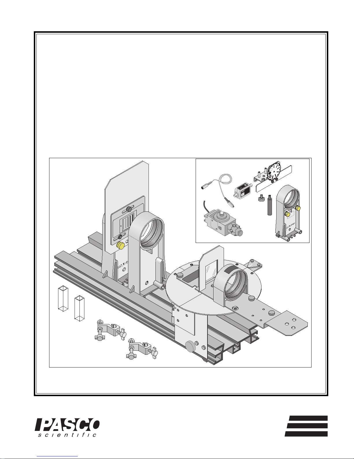
EDUCATIONAL SPECTROPHOTOMETER
ACCESSORY KIT AND EDUCATIONAL
SPECTROPHOTOMETER SYSTEM
G
G
A
A
1
1
I
I
N
N
1
1
0
0
1
1
0
0
0
0
A
A
4
4
0
0
6
6
6
6
-
-
I
I
C
C
LIGHT
LIGHT
SENSOR
SENSOR
POLARIZER MOUNTPOLARIZER MOUNT
© 1998 PASCO scientific $10.00
®
10101 Foothills Blvd. • Roseville, CA 95747-7100 USA
Phone (916) 786-3800 • FAX (916) 786-8905 • web: www.pasco.com
better
ways to
teach science


012-06575A Educational Spectrophotometer
T able of Contents
Section Page
Copyright, Warranty, and Equipment Return .....................................................ii
Quick Start........................................................................................................1
Introduction ......................................................................................................3
Description .......................................................................................................4
Set Up
Mounting the Rotary Motion Sensor ...........................................................5
Mounting the Degree Plate and Light Sensor Arm .......................................6
More Information About the Degree Plate ................................................... 6
Mounting the Aperture Bracket Light Sensor Mount and Light Sensor ........ 7
Mounting the Grating Mount.......................................................................8
Mounting the Spectrophotometer Base on the Optics Bench ........................8
Rod Stand Mounting Clamps ......................................................................8
Mounting the Collimating Slits and Lens.....................................................9
Positioning the Collimating Slits and Lens...................................................9
Mounting the Grating.................................................................................10
Mounting and Positioning the Focusing Lens .............................................10
Procedures
Turning the Degree Plate............................................................................ 11
Masking the Light Source or the Spectrophotometer................................... 11
Using the ScienceWorkshop Program .........................................................11
General Information About the Light Sensor ..............................................12
General Information About Slit Widths ......................................................12
Scanning a Spectrum.................................................................................. 12
Calibrating the Grating ...............................................................................13
Other Information ......................................................................................13
Activities
Activity 1: Emission Spectrum ................................................................... 15
Activity 2: Absorption Spectrum ................................................................ 19
Teacher’s Guide...............................................................................................23
Technical Support ......................................................................... Inside Back Cover
i

Educational Spectrophotometer 012-06575A
Copyright, Warranty and Equipment Return
Please—Feel free to duplicate this manual
subject to the copyright restrictions below.
Copyright Notice
The PASCO scientific manual for the Model OS-8537
Educational Spectrophotometer Accessory Kit and OS8539 Educational Spectrophotometer System is copyrighted and all rights reserved. However, permission is
granted to non-profit educational institutions for reproduction of any part of this manual providing the reproductions are used only for their laboratories and are not sold
for profit. Reproduction under any other circumstances,
without the written consent of PASCO scientific, is
prohibited.
Limited Warranty
PASCO scientific warrants this product to be free from
defects in materials and workmanship for a period of one
year from the date of shipment to the customer. PASCO
will repair or replace, at its option, any part of the product
which is deemed to be defective in material or workmanship. This warranty does not cover damage to the product
caused by abuse or improper use. Determination of
whether a product failure is the result of a manufacturing
defect or improper use by the customer shall be made
solely by PASCO scientific. Responsibility for the return
of equipment for warranty repair belongs to the customer.
Equipment must be properly packed to prevent damage
and shipped postage or freight prepaid. (Damage caused
by improper packing of the equipment for return shipment will not be covered by the warranty.) Shipping costs
for returning the equipment, after repair, will be paid by
PASCO scientific.
Equipment Return
Should this product have to be returned to PASCO
scientific, for whatever reason, notify PASCO scientific
by letter or phone BEFORE returning the product. Upon
notification, the return authorization and shipping instructions will be promptly issued.
When returning equipment for repair, the units must be
packed properly. Carriers will not accept responsibility
➤ NOTE:
NO EQUIPMENT WILL BE ACCEPTED FOR
RETURN WITHOUT AN AUTHORIZATION.
for damage caused by improper packing. To be certain
the unit will not be damaged in shipment, observe the
following rules:
➀ The carton must be strong enough for the item
shipped.
➁ Make certain there is at least two inches of packing
material between any point on the apparatus and the
inside walls of the carton.
➂ Make certain that the packing material can not shift in
the box, or become compressed, thus letting the instrument come in contact with the edge of the box.
Address: PASCO scientific
Credits
Edited by: Dave Griffith
10101 Foothills Blvd.
Roseville, CA 95747-7100
Phone: (916) 786-3800
FAX: (916) 786-8905
ii
012-06575A Quick Start Educational Spectrophotometer
10
1
100
GAIN
H
IG
H
S
E
N
S
IT
IV
IT
Y
L
IG
H
T
S
E
N
S
O
R
C
I
-
6
6
0
4
Quick Start
The following pages give an overview of the Spectrophotometer equipment setup.
Step One: Prepare the Rotary Motion Sensor by
removing the thumbscrew, three-step pulley, and
rod clamp.
thumbscrew
three-step pulley
Spectrophotometer Base
Put the Pinion
on the shaft.
Rotary Motion Sensor
rod clamp
Quick Start 1: Prepare Rotary Motion Sensor
Step Two: Prepare the Spectrophotometer Base by
removng the two small thumbscrews and Pinion
and by rotating the hinge away from the Base.
Spectrophotometer Base
hinge
Use the thumbscrews to
attach the sensor.
Rotary Motion
Sensor
Quick Start 3: Attach the Sensor and Pinion
Step Four: Put the Degree Plate/Light Sensor
Arm on the Base. Attach the Grating Mount,
Light Sensor Mount, and Light Sensor. Position
the Focusing Lens.
Light
Sensor
Light Sensor Mount with
Aperture Disk and Screen
Focusing
Lens
Grating
Mount
Degree
Plate
Remove the
Pinion
Rotate the
hinge.
Quick Start 2: Prepare the Hinge
Step Three: Attach the Rotary Motion Sensor to
the Base hinge with the two small thumbscrews and
attach the Pinion to the Rotary Motion Sensor shaft.
Remove the
thumbscrews.
Light
Sensor
Arm
lock washer
wing nut
Quick Start 4: Degree Plate & Light Sensor Arm, Grating Mount,
Focusing Lens, Light Sensor Mount, and Light Sensor
1
threaded
post
Educational Spectrophotometer Quick Start 012-06575A
Step Five: Put the Spectrophotometer Base onto one
end of the Optics Bench.
Base
T-slot
Quick Start 5: Put Base onto Optics Bench
Optics Bench
hinge
thumbscrew
square nut
Step Six: Mount the Collimating Slits and Collimating
Lens onto the Optics Bench. Set up a light source.
Adjust the Collimating Slits and Collimating Lens to
collimate the light beam.
Step Eight: Set up the experiment in the
ScienceWorkshop program.
1. Select the Light Sensor for Analog Channel A.
2. Select the Rotary Motion Sensor for Digital
Channels 1 and 2.
3. Set the Rotary Motion Sensor to high resolution
(1440 Divisions/Rotation).
4. Create a calculation for “Actual Angular Position” based on the Angular Position data from the
Rotary Motion Sensor and the ratio of the radius
of the Degree Plate to the radius of the small post
on the Pinion (typically, a 60 to 1 ratio).
5. Select a Graph display. Set the vertical axis to
Light Intensity and the horizontal axis to your
calculation of “Actual Angular Position”.
6. Set the sampling rate to 20 Hz (20 measurements
per second).
Step Nine: Scan the Spectrum
1. Mask or hood the light source if necessary.
light
source
Collimating
Lens
Collimating
Slits
Quick Start 6: Setup for Collimation
light ray
path
Degree
Plate
1
0
0
1
0
1
G
A
IN
Step Seven: Attach the Grating to the mount so the
glass side of the Grating faces the light source.
glass side faces light source
Grating
2. Move the Light Sensor Arm so the Light Sensor
is beyond the edge of the first order spectral
pattern.
3. Start recording data. Slowly and continuously
scan the spectrum. Scan the first order spectrum
on one side of the central ray, through the central
ray, and through the first order spectrum on the
other side.
Scan slowly and
continuously in one
direction.
central ray
(“zeroth order”)
first order spectral lines
Grating
first order spectral lines
100
10
1
GAIN
Quick Start 7: Attach the Grating
CAUTION: Avoid touching the Grating surface.
Quick Start 9: Scan the Spectrum
Step Ten: Analyze Your Data
2
012-06575A Educational Spectrophotometer
Introduction
About This Manual
This manual describes the PASCO OS-8537 Educational Spectrophotometer Accessory Kit and the PASCO OS-8539
Educational Spectrophotometer System. The OS-8537 Accessory Kit is designed to be mounted on the Optics Bench of
the OS-8515 Basic Optics System.
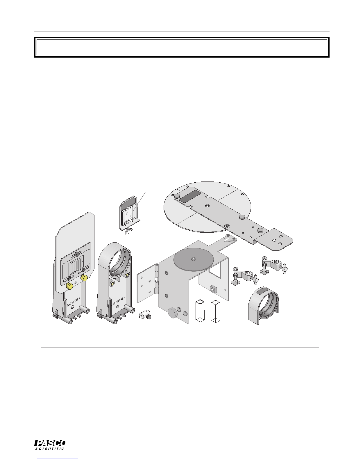
Components of the Kit
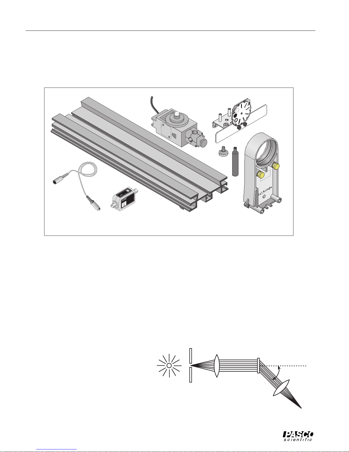
The OS-8537 Educational Spectrophotometer Accessory Kit (see Figure 1a) includes the following items:
Spectrophotometer Base Degree Plate with Light Sensor Arm
Grating Mount Grating (~600 lines per mm)
Focusing Lens Collimating Lens
Collimating Slits Cuvettes (2)
Rod Stand Mounting Brackets (2)
Collimating Slits
Grating
Grating Mount
Spectrophotometer
Base
Collimating Lens
Pinion*
Cuvettes (2)
Figure 1a: Educational Spectrophotometer Accessory Kit
Degree Plate
Light Sensor Arm
Rod Stand Mounting
Clamps (2)
Focusing Lens
(*The pinion shown in Figure 1a can be mounted on a post on the Spectrophotometer Base when not in use.)
Recommended Equipment for use with the Spectrophotometer Accessory Kit:
Basic Optics System (OS-8515) High Sensitivity Light Sensor (CI-6604)
Aperture Bracket (OS-8534) Rotary Motion Sensor (CI-6538)
3
Educational Spectrophotometer 012-06575A
Components of the System
The OS-8539 Educational Spectrophotometer System includes the items in the Spectrophotometer Accessory Kit
plus the following:
Optics Bench (60 cm) Rotary Motion Sensor (CI-6538)
High Sensitivity Light Sensor (CI-6604) Aperture Bracket (OS-8534)
Rotary Motion Sensor
G
A
1
I
N
1
0
1
0
0
A
4
0
6
I-6
C
LIGHT
SENSOR
High Sensitivity Light SensorDIN-to-DIN cable Optics Bench (60 cm)
Figure 1b: Additional Components of the Spectrophotometer System
Recommended Equipment for use with both the Kit and the System:
Light Source (such as OS-9286 Mercury Light) Large Rod Stand (ME-8735) (2)
Rod, 45 cm (ME-8736) (2)
Aperture Bracket
T
N
U
O
M
R
E
IZ
R
A
L
O
P
Aperture Bracket Holder
Description
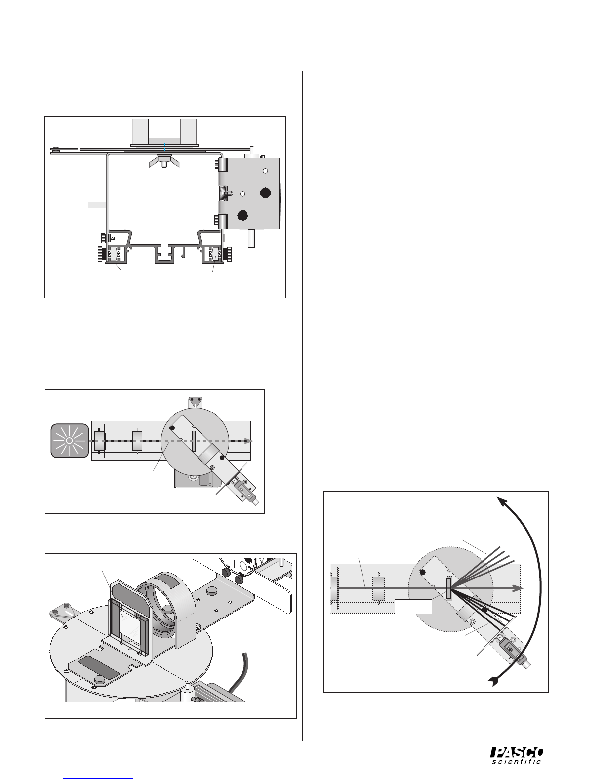
The Spectrophotometer allows you to view and measure the spectral pattern (spectrum) produced by a light source.
The Collimating Slits and Collimating Lens produce a narrow beam of parallel light rays. The Grating disperses
the beam of light into a spectrum with different colors at different angles but with all of the light of a given color
in a parallel beam. The Focusing Lens focuses these parallel beams of color into spectral lines (see Fig. 2). The
narrow slit on the Aperture Disk (part of the Aperture Bracket) allows light of a single color to enter the High Sensitivity Light Sensor. The High Sensitivity Light Sensor (included with the Spectrophotometer System) measures
the intensity of the light while the Rotary Motion Sensor (included with the Spectrophotometer System) measures
the angle to which the light is diffracted by the
Grating.
You can find the wavelength of each color of
light using the measured angle and the Grating
spacing “d”.
mλ = d sin θ, m = 0, 1, 2…
where d is the distance between the rulings on
the Grating, m is the order of the particular
principal maximum, θ is the angle of the
diffracted light, and λ is the wavelength.
Light Source
Collimating Slit
4
Collimating Lens
Diffraction Grating
Focusing Lens
spectral line
Figure 2: Grating Spectrometer
θ
012-06575A Educational Spectrophotometer
The Grating disperses the beam of
light into a first order spectrum
and higher order spectra. The
Optics Bench
Collimating Lens
higher order spectra are broader
and less bright than the first order
spectra, and may overlap.
The Grating is blazed, so one side
Light Source
of the spectrum is much brighter
than the other.
Collimating Slit
Rotary Motion Sensor
Figure 3: Spectrophotometer System (Top View)
Set Up
This part of the manual describes how to set up the
Spectrophotometer System (see Fig. 3).
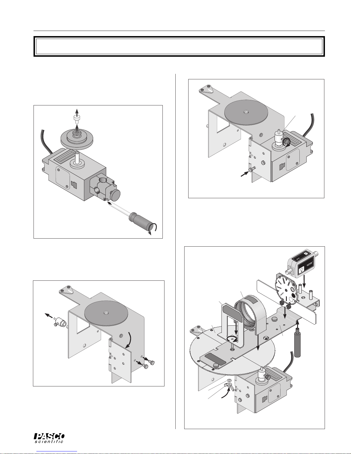
Mounting the Rotary Motion Sensor
This describes how to mount the Rotary Motion
Sensor to the hinge on the side of the Spectrophotometer Base.
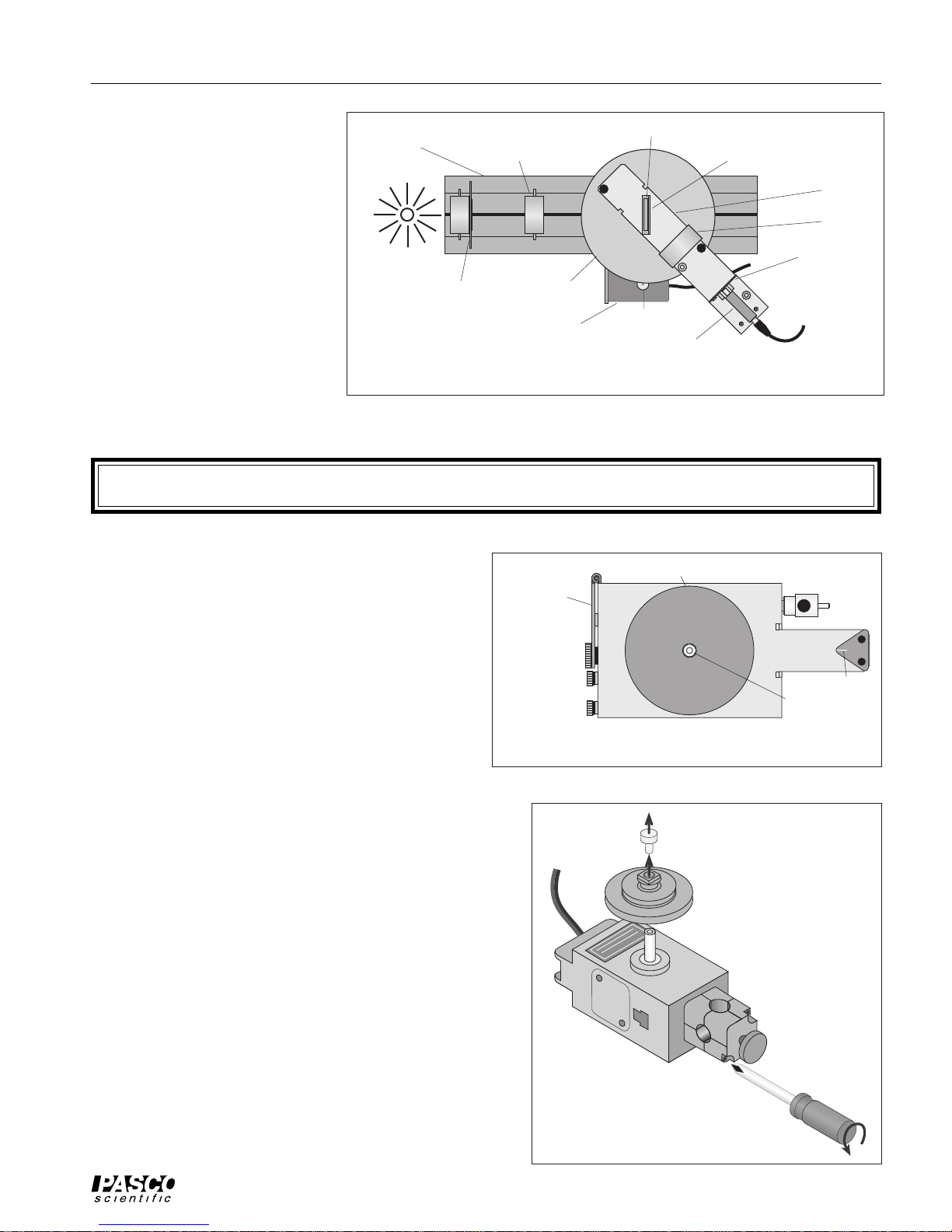
The top of the Spectrophotometer Base has a short
threaded post for centering the circular Degree Plate
and for holding the Grating Mount. It also has a
magnetic pad for holding the Degree Plate, and a
triangular shaped index marker. One side of the base
has a post upon which the Pinion can be stored when it
is not in use. The other side has a spring-loaded hinge and
two small thumbscrews for mounting the Rotary Motion
Sensor (included in the Spectrophotometer System). On
both sides of the base are thumbscrews and square nuts used
for mounting the Spectrophotometer Base on the Optics
Bench (see Fig. 4).
The Rotary Motion Sensor has a three step pulley attached
to its shaft with a small thumbscrew. The sensor also has a
rod clamp attached at end end.
First, remove the small thumbscrew and three step pulley
from the Rotary Motion Sensor shaft. Then, remove the rod
clamp from the Rotary Motion Sensor (see Fig. 5).
Diffraction Grating
Grating Mount
Light Sensor Arm
Focusing Lens
Aperture Disk
Degree Plate
Pinion
High Sensitivity Light Sensor
magnetic pad
hinge
large
thumbscrew
small
thumbscrews
Spectrophotometer Base
Pinion
threaded post
Figure 4: Spectrophotometer Base (Top View)
thumbscrew
three-step pulley
Rotary Motion Sensor
rod clamp
index
Figure 5: Prepare Rotary Motion Sensor
5
Educational Spectrophotometer 012-06575A
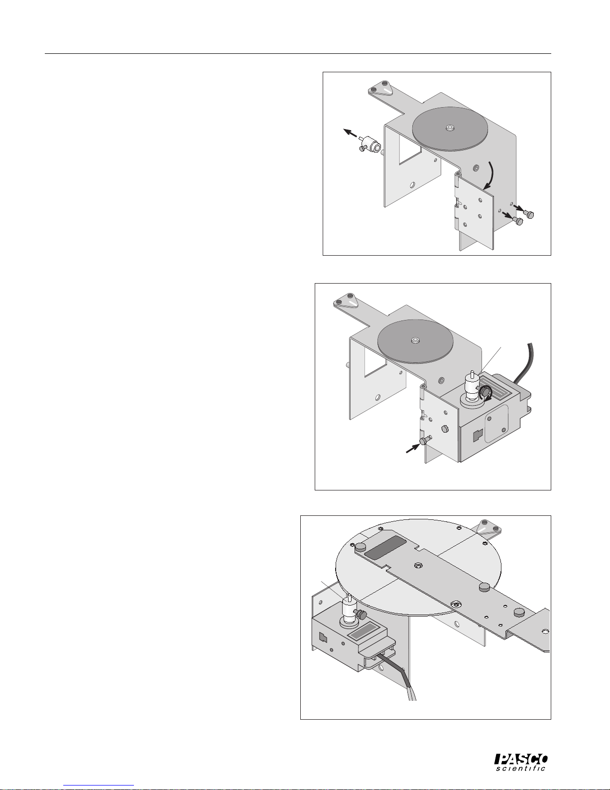
Remove the two small thumbscrews from the threaded
storage holes on the side of the Spectrophotometer Base
and set them aside for the moment. Remove the Pinion
from the storage post on the opposite side of the Spectrophotometer Base and set the Pinion aside for a moment (see
Fig. 6).
Rotate the hinge away from the side of the base until the
hinge is almost perpendicular to the base. Use the two
small thumbscrews to fasten the Rotary Motion Sensor to
the lower set of holes on the inside of the hinge.
Place the Pinion all the way onto the Rotary Motion Sensor
shaft and tighten the Pinion on the shaft by turning the
small thumbscrew on the side of the Pinion (see Fig. 7).
Connect the Rotary Motion Sensor plugs into the
ScienceWorkshop interface.
Mounting the Degree Plate and Light Sensor Arm
The Degree Plate and Light Sensor Arm are shipped as a
unit. The Light Sensor Arm is attached to the circular
Degree Plate with two small thumbscrews. The hole in
the center of the Degree Plate fits over the short threaded
post on the top of the Spectrophotometer Base.
Spectrophotometer Base
Remove the
Pinion
Rotate the
hinge.
Figure 6: Prepare the Hinge
Spectrophotometer Base
Remove the
thumbscrews.
Put the Pinion
on the shaft.
Hold the Rotary Motion Sensor slightly away from the
base so the small diameter post on top of the Pinion is not
in the way of the edge of the Degree Plate. Position the
hole in the plate over the short threaded post on the top of
the base. Place the Degree Plate onto the Spectrophotometer Base. Let the small diameter post on the top of the
Pinion rest against the edge of the Degree Plate (see Fig.
8).
More Information About the Degree Plate
The ratio between the radius of the Degree Plate and
the radius of the small post on the top of the Pinion is
designed to be 60 to 1. In other words, the Pinion
rotates 60 times for one rotation of the Degree Plate.
This assumed ratio of 60 to 1 is included in a calculation for the actual angular displacement of the Degree
Plate as it turns during the measurement of a spectrum
(see “Using the ScienceWorkshop Program” in the
Procedure section).
Using the exact ratio of the Degree Plate to the small
Pinion post can slightly improve the accuracy of
measurement. To determine the exact ratio of the
Degree Plate to the small Pinion post, do the following
to calibrate the Degree Plate:
Use the thumbscrews to
attach the sensor.
Figure 7: Attach the Sensor and Pinion
Pinion
Rotary Motion
Sensor
Figure 8: Degree Plate onto Base
hinge
Rotary Motion
Sensor
Degree Plate
Light Sensor
Arm
Let the post on top of the
Pinion rest against the
edge of the Degree Plate.
6
 Loading...