

Pasco Scientific ME-8950 Instruction Manual And Experiment Manual
Instruction Manual and
1
Experiment Guide for
the PASCO scientific
Model ME-8950
COMPLETE ROTATIONAL
SYSTEM
012-05293E
8/97
© 1994 PASCO scientific $10.00
ACCESSORY
ROTATIONAL INERTIA
R
A
O
I
T
T
A
T
I
O
I
NER
L
N
A
A
C
RY
C
O
S
E
S
Complete Rotational System 012-05293E
2
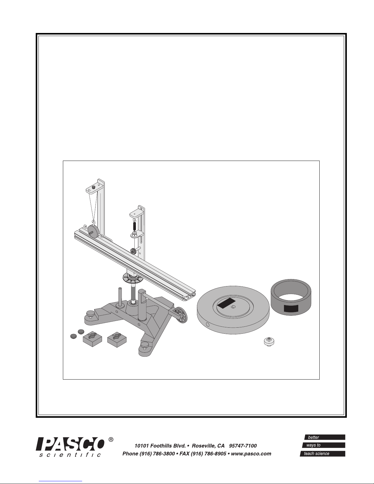
Equipment
300g square mass (2)
with thumbscrews and
square nuts
low-profile
thumbscrew
assemblies (2)
photogate
mounting rod
accessory
mounting rod
aluminum rotating
platform
cast iron "A" base
"E" rings (2, 1 extra)
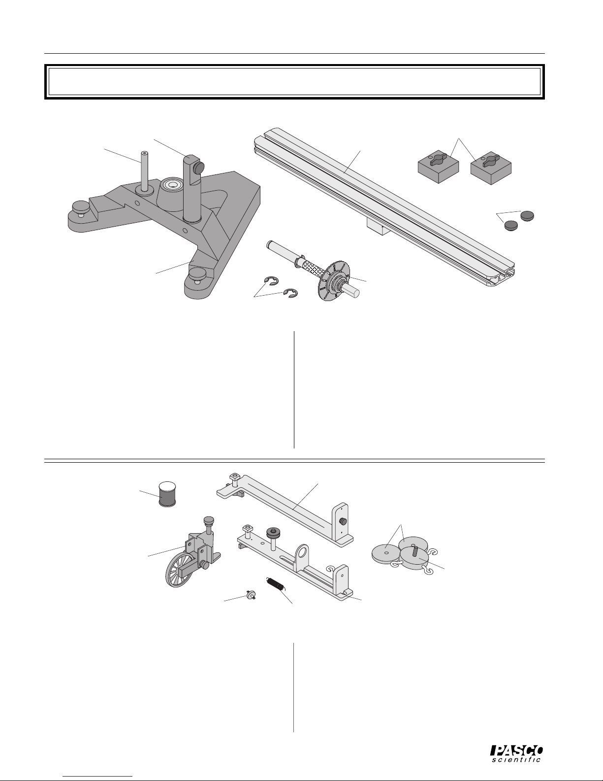
ME-8951 Rotating Platform Equipment
The ME-8951 Rotating Platform Includes the
following:
- PASCO cast iron “A” base with rotating shaft
and pulley with 10 holes
- aluminum track
- two square masses (about 300 g) with thumb
screw and square nut
spool of thread
clamp-on
pulley
rotating vertical shaft
with 10-hole pulley
- two additional low-profile screws and square nuts
to act as stops for the square mass in the Conservation of Angular Momentum experiment
- accessory mounting rod for mounting the 10spoke pulley or the optional Smart Pulley photogate head
- accessory mounting rod for mounting PASCO
Photogate (ME-9498A, ME-9402B or later)
side post
50g masses (2)
100g mass with 3
open hooks
plastic
indicator disk
ME-8952 Centripetal Force Accessory Equipment
The ME-8952 Centripetal Force Accessory
includes:
- center post that supports an indicator mechanism which consists of a small pulley, a movable spring holder, a movable indicator, a
spring, and a plastic indicator disk
- side post for hanging hooked mass
spring
center post
- mass (100 g) with 3 open hooks
- 2 additional 50 gram masses
- clamp-on pulley
- 1 spool of thread
2
Complete Rotational System 012-05293E
3
Assembly
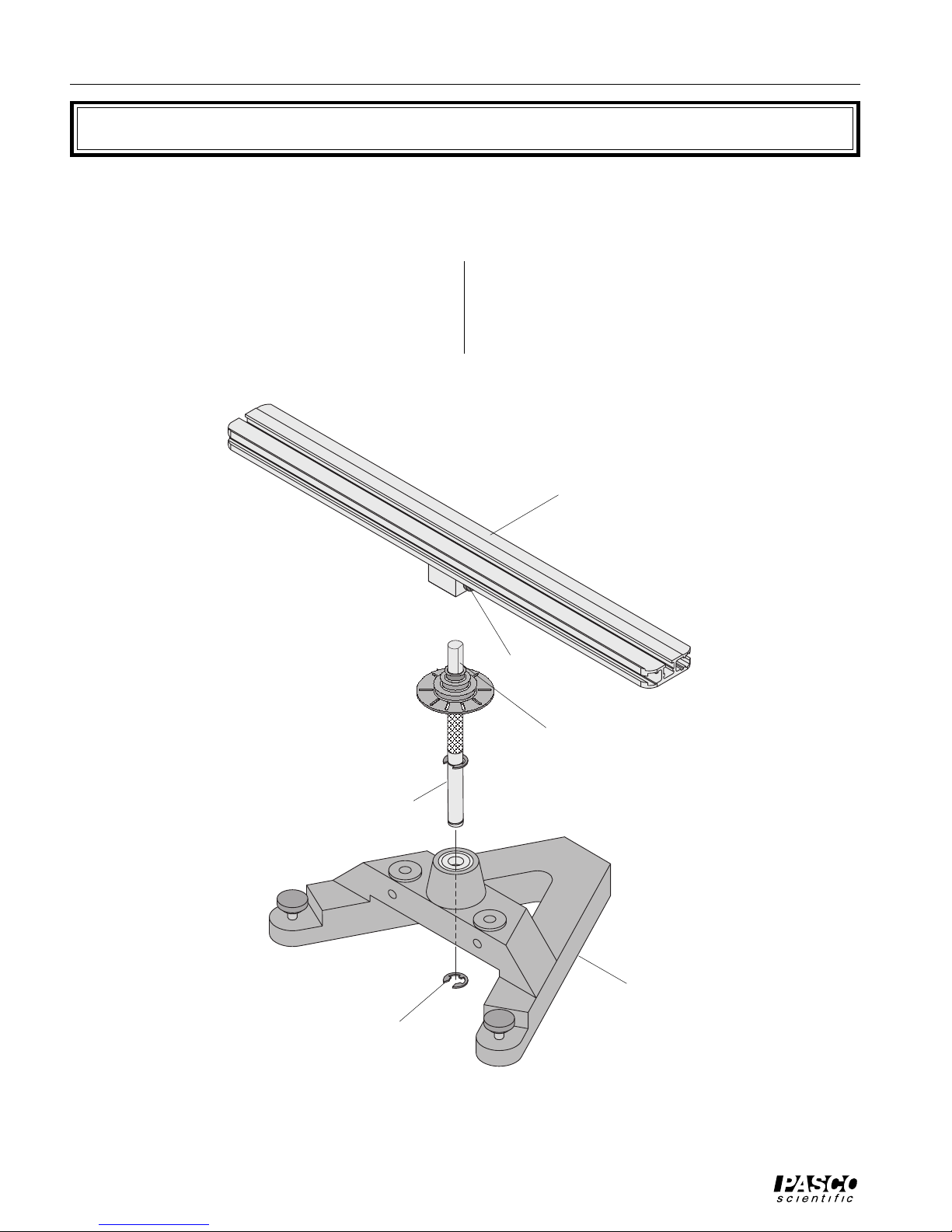
ME-8951 Rotating Platform
Assembling the Rotating Platform
➀ Insert the cylindrical end of the shaft into the bear-
ings on the top-side of the A-shaped iron base. Secure the shaft in place by inserting the "E" ring in
the slot at the bottom of the shaft. See Figure 1.
➁ Mount the track to the shaft and tighten the thumb
screw against the flat side of the “D” on the shaft.
See Figure 1.
rotating platform
thumbscrew
flat of vertical shaft
vertical shaft
"A" base
"E" ring
Figure 1: Attaching the Vertical Shaft to the Base and Rotating Platform Assembly
4

012-05293E Complete Rotational System
4
rotating
platform
20
191817161514131211 24232221
300g square
mass
Leveling the Base
"A" base
20
010
123456789
111213141516171819212224
leveling
feet
10
987654321
adjust this foot
Figure 2: Leveling the Base
Some experiments (such as the Centripetal Force
experiments) require the apparatus to be extremely
level. If the track is not level, the uneven performance
will affect the results. To level the base, perform the
following steps:
➀ Purposely make the apparatus unbalanced by at-
taching the 300 g square mass onto either end of the
aluminum track. Tighten the screw so the mass will
not slide. If the hooked mass is hanging from the
side post in the centripetal force accessory, place
the square mass on the same side.
rotating platform
(rotated 90˚ as shown)
010
123456789
111213141516171819212224
20
first
20
191817161514131211 24232221
then adjust this
foot
10
987654321
➁ Adjust the leveling screw on one of the legs of the
base until the end of the track with the square mass
is aligned over the leveling screw on the other leg
of the base. See Figure 2.
➂ Rotate the track 90 degrees so it is parallel to one
side of the “A” and adjust the other leveling screw
until the track will stay in this position.
➃ The track is now level and it should remain at rest
regardless of its orientation.
300g square
mass
Installing the Optional Smart Pulley Photogate Head
The black plastic rod stand is designed to be used in
two ways:
• It can be used to mount a Smart Pulley photogate
head to the base in the correct position to use the
10 holes in the pulley on the rotating shaft to measure angular speed.
• It can be used to mount a Smart Pulley (with the pulley and rod) to the base to run a string over the pulley.
To Use the Photogate Head Only:
➀ To install, first mount the black rod to the base by
inserting the rod into either hole adjacent to the
center shaft on the base.
➁ Mount the Smart Pulley photogate head horizon-
tally with the cord side down. Align the screw hole
in the photogate head with the screw hole in the flat
side of the black rod. Secure the photogate head
with the thumb screw. See Figure 3.
➂ Loosen the thumb screw on the base to allow the
black rod to rotate. Orient the rod and photogate
head so the infrared beam passes through the holes
photogate
mount rod
"A" base
thumbscrew
10-spoke
pulley on
vertical shaft
Smart Pulley
photogate head
(optional)
accessory
mounting rod
thumbscrew
Figure 3: Using the Accessory Mounting Rod With
the Smart Pulley
in the pulley. If the photogate head is powered by a
computer, you can tell when the photogate is
blocked by watching the LED indicator on the end
of the photogate. The photogate head should not be
rubbing against the pulley. When the head is in the
correct position, tighten the bottom screw to fix the
rod in place.
nylon
5
 Loading...