

Includes
Teacher's Notes
and
Typical
Experiment Results
Instruction Manual and
Experiment Guide for the
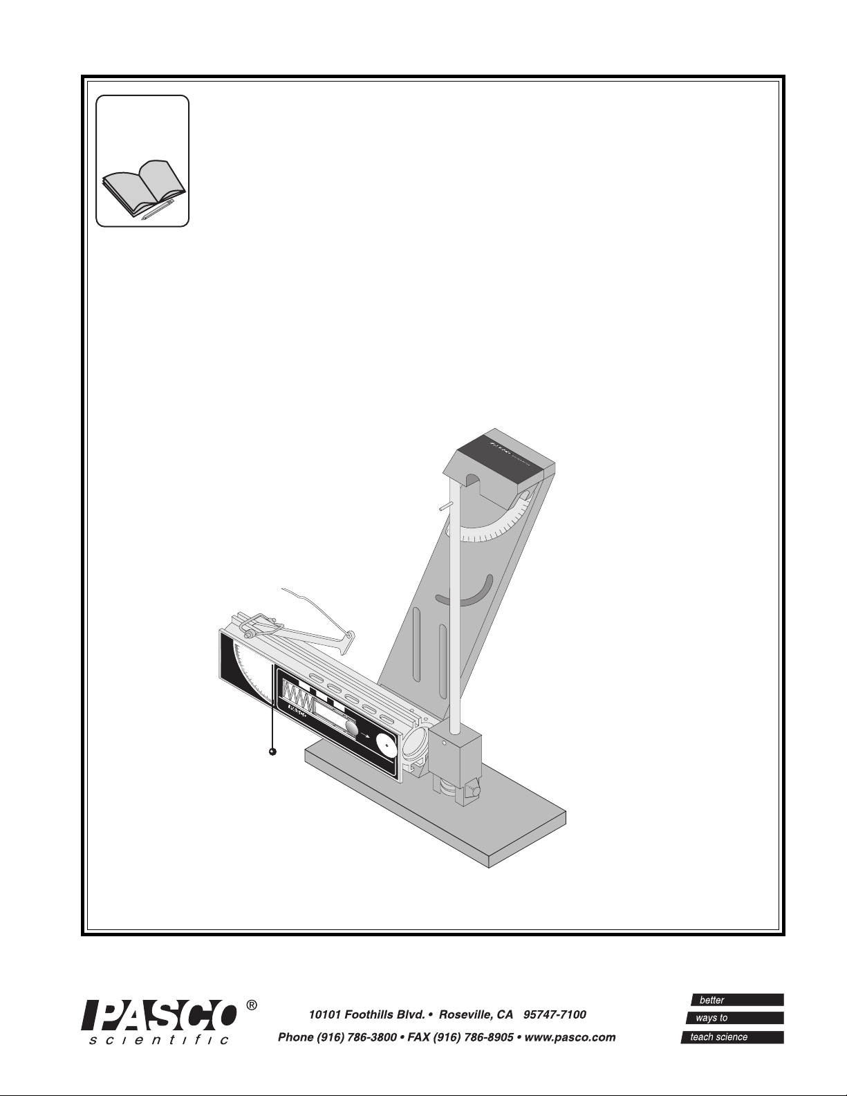
PASCO s c i e n t i f i c Model
ME-6830/ME-6831
Ballistic Pendulum /
Projectile Launcher
012-05375B
2/99
WEAR
SAFETY
GLASSES
WHEN IN USE.
ME-6800
LONG
RANGE
MEDIUM
RANGE
SHORT
RANGE
CAUTION!
CAUTION!
DO NOT LOOK
DO NOT LOOK
Yellow Band in Window
DOWN BARREL!
DOWN BARREL!
Indicates Range.
Use 25 mm
PROJECTILE LAUNCHER
SHORT RANGE
balls ONLY!
Launch
Position
of Ball
© 1993 PASCO scientific $10.00


012-05375B Ballistic Pendulum/Projectile Launcher
Table of Contents
Section Page
Copyright, Warranty, and Equipment Return................................................... ii
Introduction ...................................................................................................... 1
Equipment......................................................................................................... 2
General Operation Of The Projectile Launcher ................................................ 3
Theory of operation for Ballistic Pendulum ..................................................... 4
Installation Of The Optional Photogate Bracket .............................................. 6
Installing the 2-Dimensional Collision Attachment ......................................... 7
Expectations For The Projectile Launcher ....................................................... 7
Expectations for the Ballistic Pendulum .......................................................... 7
Experiments
1. Projectile Motion ........................................................................................ 9
2. Projectile Motion Using Photogates ......................................................... 13
3. Projectile Range versus Angle.................................................................. 17
4. Projectile Path ........................................................................................... 21
5. Conservation of Energy ............................................................................ 25
6. Conservation of Momentum in Two Dimensions .................................... 29
7. Varying Angle to Maximize Height on a Wall......................................... 33
8. Ballistic Pendulum approximate method.................................................. 35
9. Ballistic Pendulum exact method ............................................................. 37
10. Demo: Do 30⋅ and 60⋅ Give Same Range? ........................................... 39
11. Demo: Simultaneously Shoot Two Balls
Horizontally at Different Speeds ........................................................ 41
12. Demo: Shoot through Hoops ................................................................. 43
13. Demo: Elastic / Inelastic Collisions ...................................................... 45
Teachers Guide ............................................................................................... 46
Technical Support ............................................................................ Back Cover
®
i
Ballistic Pendulum/Projectile Launcher 012-05375B
Copyright, Warranty and Equipment Return
Please—Feel free to duplicate this manual
subject to the copyright restrictions below.
Copyright Notice
The PASCO scientific 012-05375 manual is copyrighted
and all rights reserved. However, permission is granted to
non-profit educational institutions for reproduction of any
part of the Ballistic Pendulum/Projectile Launcher
manual providing the reproductions are used only for
their laboratories and are not sold for profit. Reproduction
under any other circumstances, without the written
consent of PASCO scientific, is prohibited.
Limited Warranty
PASCO scientific warrants the product to be free from
defects in materials and workmanship for a period of one
year from the date of shipment to the customer. PASCO
will repair or replace, at its option, any part of the product
which is deemed to be defective in material or workmanship. The warranty does not cover damage to the product
caused by abuse or improper use. Determination of
whether a product failure is the result of a manufacturing
defect or improper use by the customer shall be made
solely by PASCO scientific. Responsibility for the return
of equipment for warranty repair belongs to the customer.
Equipment must be properly packed to prevent damage
and shipped postage or freight prepaid. (Damage caused
by improper packing of the equipment for return shipment will not be covered by the warranty.) Shipping costs
for returning the equipment, after repair, will be paid by
PASCO scientific.
Equipment Return
Should the product have to be returned to PASCO
scientific, for whatever reason, notify PASCO scientific
by letter, phone, or fax BEFORE returning the product.
Upon notification, the return authorization and shipping
instructions will be promptly issued.
➤ ➤
➤ NOTE: NO EQUIPMENT WILL BE
➤ ➤
ACCEPTED FOR RETURN WITHOUT AN
AUTHORIZATION.
When returning equipment for repair, the units must be
packed properly. Carriers will not accept responsibility
for damage caused by improper packing. To be certain
the unit will not be damaged in shipment, observe the
following rules:
➀ The carton must be strong enough for the item
shipped.
➁ Make certain there is at least two inches of packing
material between any point on the apparatus and the
inside walls of the carton.
➂ Make certain that the packing material can not shift in
the box, or become compressed, thus letting the
instrument come in contact with the edge of the box.
Address: PASCO scientific
10101 Foothills Blvd.
Roseville, CA 95747-7100
Phone: (916) 786-3800
Credits
Author: Ann Hanks and Eric Ayers
FAX: (916) 786-8905
email: techsupp@pasco.com
ii
®
012-05375B Ballistic Pendulum/Projectile Launcher
Introduction
The PASCO ME-6830/ME-6831 Ballistic Pendulum/
Projectile Launcher (BPPL) has been designed for
projectile experiments and demonstrations as well as the
classic Ballistic Pendulum experiments. The only
additional equipment required is a C-clamp for clamping
the launcher to a table. The features of the Ballistic
Pendulum/Projectile Launcher include:
• LAUNCH AT ANY ANGLE: Balls can be
launched at any angle from zero to 90 degrees measured from the horizontal. The angle is easily adjusted using thumb screws. The built-in protractor
and plumb-bob on the side of the launcher give a convenient and accurate way of determining the angle of
inclination.
• THREE RANGE SETTINGS: There are three
ranges from which to choose. For the Short Range
Projectile Launcher these three ranges are approximately 1.2 meters, 3 meters, and 5 meters, when the
angle is 45 degrees. For the Long Range Demonstration Projectile Launcher, the three ranges are approximately 2.5 meters, 5 meters, and 8 meters. The difference between these two versions of the Projectile
Launcher is the strength of the spring. The long range
version is intended for large classroom demonstrations and should not be used with the Ballistic Pendulum base.
➤ ➤
➤ IMPORTANT: Experimental results can be
➤ ➤
further improved by making sure that the ball does
not stick to the blue vibration damping ring prior to
being launched. This is particularly critical for the
long range setting and for launching angles above
30°. To assure the ball does not stick to the ring,
push it gently with a pencil from the back of the barrel.
• BARREL SIGHTS AND SAFETY PRECAU-
TIONS: The sights for aiming the Projectile
Launcher can be viewed from the back of the launcher
by looking through the back end of the barrel.
➤➤
➤WARNING: Never look down the front of the
➤➤
barrel because it may be loaded. To see if the ball is in
the barrel and to check whether the Projectile Launcher
is cocked, look at the slots in the side of the barrel.
The yellow indicator seen through the side slot
indicates the position of the piston. The ball can also
be seen through these slots when it is in the piston.
• COMPUTER COMPATIBLE: Photogates can be at-
tached with the ME-6821 Photogate Mounting Bracket
to connect the Projectile Launcher to a computer for measuring the muzzle speed. Also, a photogate at the muzzle
and an ME-6810 Time-of-Flight Accessory can be used
to time the flight of the ball.
• FIXED ELEVATION INDEPENDENT OF
ANGLE: The Projectile Launcher pivots at the
muzzle end so the elevation of the ball as it leaves the
barrel does not change as the angle is varied. The
base has three sets of slots. The top curved slot is
used when it is desired to change the angle and the
center two slots are used when it is desired to shoot
horizontally only. The bottom mounting holes are for
use with the Ballistic Pendulum experiment.
• REPEATABLE RESULTS: There is no spin on the
ball since the piston keeps the ball from rubbing on
the walls as it travels up the barrel. The sturdy base
can be secured to a table with a C- clamp (not included) so there is very little recoil. The trigger is
pulled with a string to minimize any misalignment
caused by other methods of trigger release.
®
• COMPACT STORAGE: The Projectile Launcher
stores away in a small space. The ramrod attaches to
the Projectile Launcher with Velcro® and the
launcher can be turned vertically so it takes up the
minimum amount of space on the shelf.
• RELIABLE BALL-CATCHER MECHANISM:
The sensitive spring-loaded barb-type catch on the
pendulum will catch balls with a large range of momenta. In addition, the ball is held in line with the
pendulum rod for best accuracy.
• REMOVABLE PENDULUM: All moving parts of
the pendulum may be removed so that the mass and
the center of mass can be easily determined. In addition, the pendulum can be reversed to compare the effects of inelastic and elastic collisions.
• VARIABLE-MASS PENDULUM: Masses can be
added to the bottom of the pendulum so that meaningful measurements can be taken with either heavy or
lightweight balls, over a wide range of velocities.
1

Ballistic Pendulum/Projectile Launcher 012-05375B
Equipment
The following is a description of the equipment that is
included with various models of the Ballistic Pendulum/
Projectile Launcher.
The ME-6831 Ballistic Pendulum includes the following:
•Ballistic Pendulum base (assembled)
•(2) steel balls
launcher
trigger
In addition, the ME-6830 Ballistic Pendulum/Projectile
Launcher includes:
•Short Range Launcher
•ramrod (Attached with Velcro® to stand)
•collision attachment
•(3) plastic balls
•(2) pendulum brass masses
•(2) safety goggles
ramrod
WEAR
SAFETY
GLASSES
WHEN IN USE.
ME-6800
protractor and
plumb bob
accessory groove
safety goggles (2)
ramrod
LONG
RANGE
MEDIUM
RANGE
CAUTION!
CAUTION!
DO NOT LOOK
DO NOT LOOK
DOWN BARREL!
DOWN BARREL!
PROJECTILE LAUNCHER
SHORT RANGE
SHORT
RANGE
Yellow Band in Window
Indicates Range.
Use 25 mm
Launch
balls ONLY!
Position
of Ball
Ballistic Pendulum
base
thumb
screws
brass masses
plastic balls
stainless
steel balls
collision
accessory
2
®

012-05375B Ballistic Pendulum/Projectile Launcher
General Operation of the Projectile Launcher
➀➀
➀ Ready
➀➀
-Always wear safety goggles when you are in a room
where the Projectile Launcher is being used.
-For Projectile Launcher experiments, the base of the
Ballistic Pendulum/Projectile Launcher must be
clamped to a sturdy table using the clamp of your
choice. When clamping to the table, it is often desirable to have the label side of the Launcher even
with one edge of the table so a plumb bob can be
used to locate the position of the muzzle with respect to the floor.
-The Projectile Launcher can be mounted to the
bracket using the curved slot when it is desired to
change the launch angle. It can also be mounted to
the center two slots in the base if you are only going
to launch horizontally, such as into a Dynamics
Cart.
➁ ➁
➁ Aim
➁ ➁
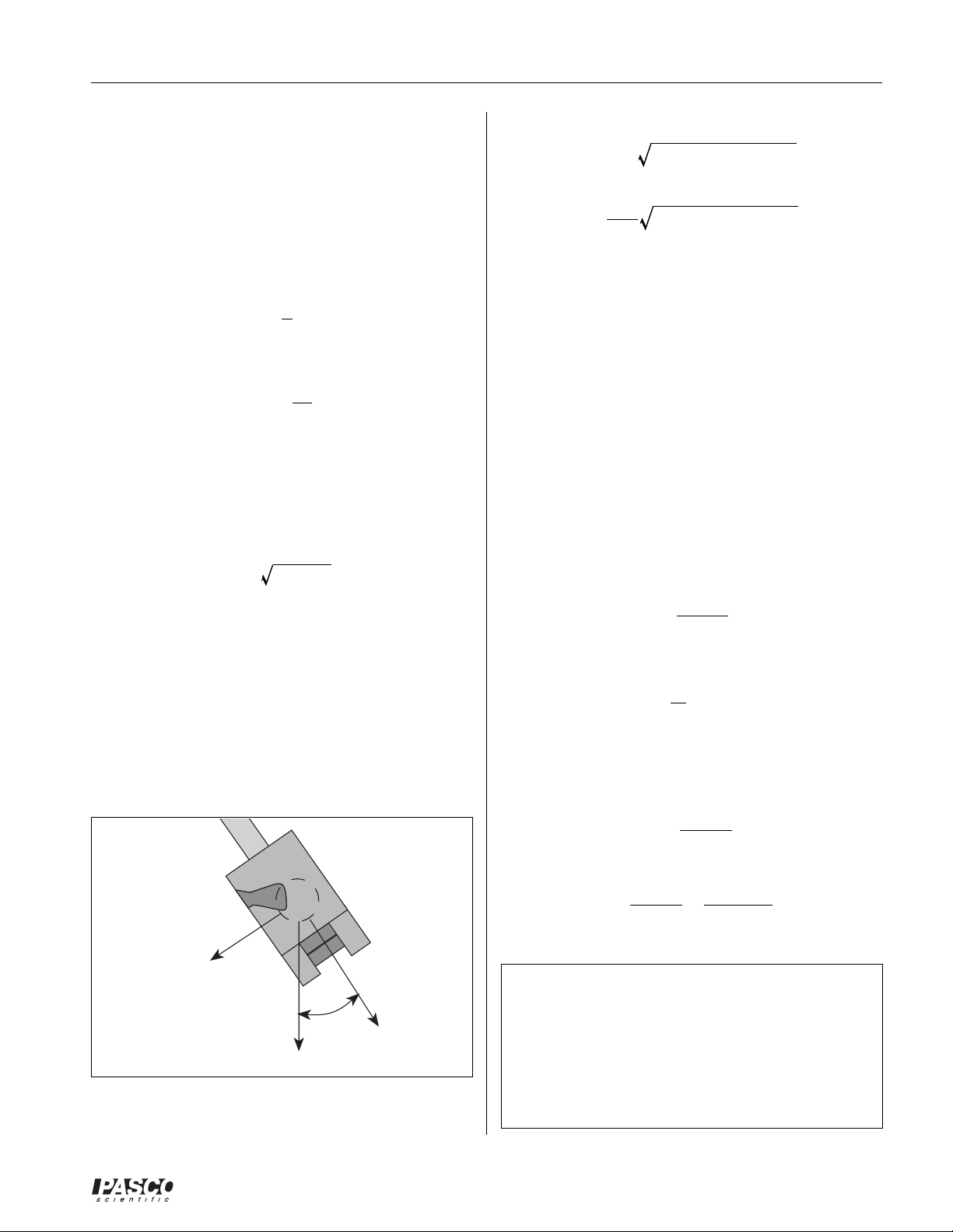
-The angle of inclination above the horizontal is adjusted by loosening both thumb screws and rotating
the Launcher to the desired angle as indicated by the
plumb bob and protractor on the side of the
Launcher. When the angle has been selected, both
thumb screws are tightened.
-You can bore-sight at a target (such as in the Monkey-Hunter demonstration) by looking through the
Launcher from the back end when the Launcher is
not loaded. There are two sights inside the barrel.
Align the centers of both sights with the target by
adjusting the angle and position of the Launcher.
-Remove the ramrod and place it back in its storage
place on the base.
-When the Projectile Launcher is loaded, the yellow
indicator is visible in one of the range slots in the
side of the barrel and the ball is visible in another
one of the slots in the side of the barrel. To check to
see if the Launcher is loaded, always check the side
of the barrel. Never look down the barrel!
➃➃
➃ Shoot
➃➃
-Before launching the ball, make certain that no person is in the way.
-To shoot the ball, pull straight up on the lanyard
(string) that is attached to the trigger. It is only necessary to pull it about a centimeter.
-The spring on the trigger will automatically return
the trigger to its initial position when you release it.
➄➄
➄
Maintenance and Storage
➄➄
-No special maintenance of the Projectile Launcher is
required.
-Do not oil the launcher!!
-To store the launcher in the least amount of space,
adjust its angle to 90 degrees. If the Photogate
Mounting Bracket and Photogates are attached to
the launcher, the bracket can be slid back along the
barrel with the photogates still attached.
➂➂
➂ Load
➂➂
-Always cock the piston with the ball in the piston.
Damage to the piston may occur if the ramrod is
used without the ball.
-Place the ball in the piston. Remove the ramrod
from its Velcro® storage place on the base. While
viewing the range-setting slots in the side of the
launcher, push the ball down the barrel with the
ramrod until the trigger catches the piston at the desired range setting.
®
3
Ballistic Pendulum/Projectile Launcher 012-05375B
1
2
ν
m
Ballistic Pendulum - Theory
Overview
The ballistic pendulum is a classic method of determining
the velocity of a projectile. It is also a good demonstration of some of the basic principles of physics.
The ball is fired into the pendulum, which then swings up
a measured amount. From the height reached by the
pendulum, we can calculate its potential energy. This
potential energy is equal to the kinetic energy of the
pendulum at the bottom of the swing, just after the
collision with the ball.
We cannot equate the kinetic energy of the pendulum
after the collision with the kinetic energy of the ball
before the swing, since the collision between ball and
pendulum is inelastic and kinetic energy is not conserved
in inelastic collisions. Momentum is conserved in all
forms of collision, though; so we know that the momentum of the ball before the collision is equal to the momentum of the pendulum after the collision. Once we
know the momentum of the ball and its mass, we can
determine the initial velocity.
There are two ways of calculating the velocity of the ball.
The first method (approximate method) assumes that the
pendulum and ball together act as a point mass located at
their combined center of mass. This method does not take
rotational inertia into account. It is somewhat quicker and
easier than the second method, but not as accurate.
The second method (exact method) uses the actual
rotational inertia of the pendulum in the calculations. The
equations are slightly more complicated, and it is necessary to take more data in order to find the moment of
inertia of the pendulum; but the results obtained are
generally better.
Please note that the subscript "cm" used in the following
equations stands for "center of mass."
Δ
PE = MgR
(1 – cosθ)
cm
Here Rcm is the distance from the pivot point to the center
of mass of the pendulum/ball system. This potential
energy is equal to the kinetic energy of the pendulum
immediately after the collision:
KE =
2
M
ν
P
2
The momentum of the pendulum after the collision is just
,
Pp= M
ν
P
which we substitute into the previous equation to give:
P
KE =
P
Solving this equation for the pendulum momentum gives:
Pp=2M(KE)
This momentum is equal to the momentum of the ball
before the collision:
.
Pb= m
ν
b
Setting these two equations equal to each other and
replacing KE with our known potential energy gives us:
mνb=2M2gRcm(1 – cos θ)
Solve this for the ball velocity and simplify to get:
M
=
b
gR
2
(1 – cosθ)
cm
R
cm
θ
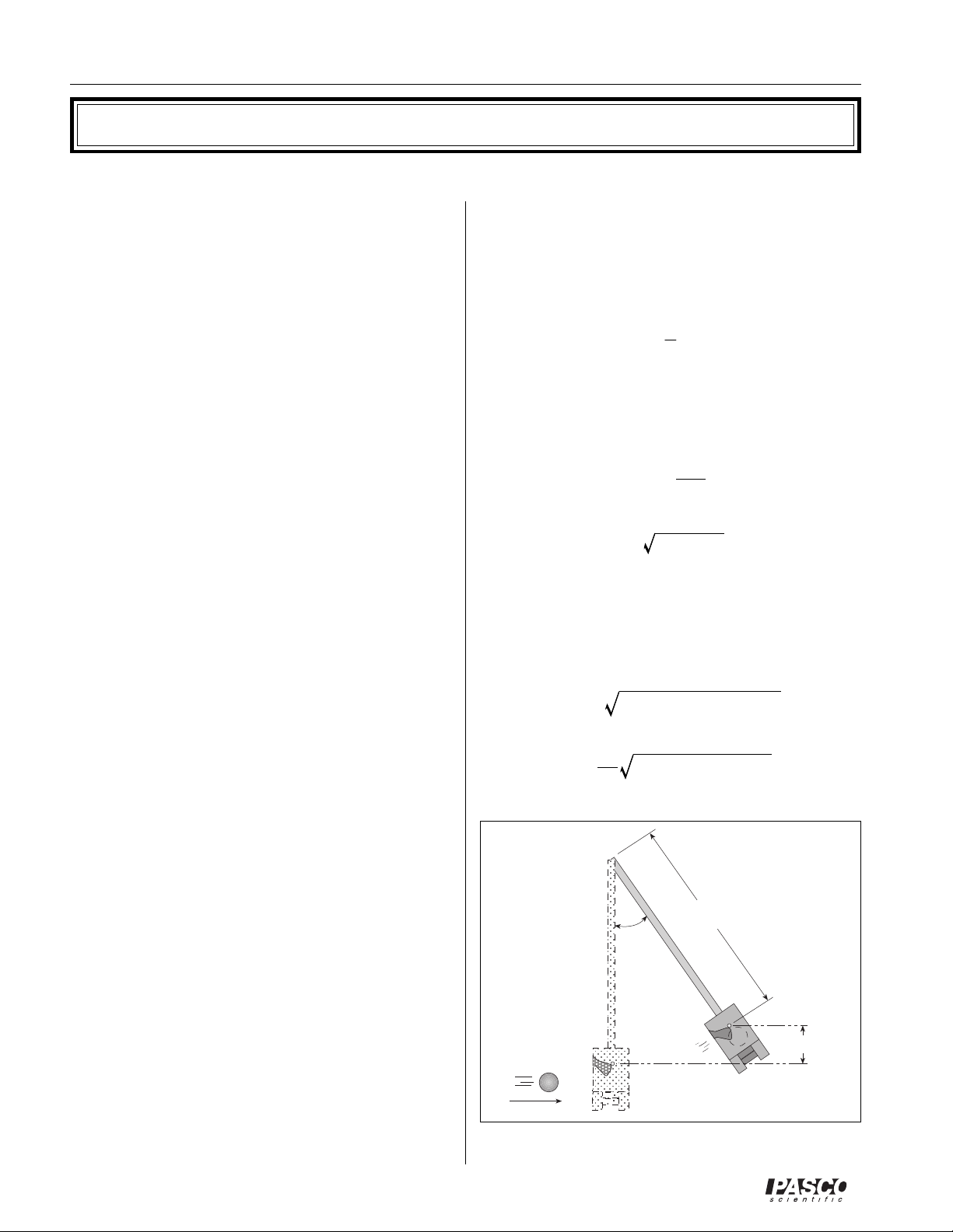
Approximate Method
Begin with the potential energy of the pendulum at the
top of its swing:
ΔPE = MgΔh
cm
m
cm
M
Where M is the combined mass of pendulum and ball, g
is the acceleration of gravity, and Δh is the change in
height. Substitute for the height:
Δ
h = R(1 – cosθ)
4
V
Figure 1
cm
cm
Δh
cm
®
012-05375B Ballistic Pendulum/Projectile Launcher
2
2
ν
1
m
2
Exact Method
The potential energy is found in a way identical to the
way shown previously:
ΔPE = MgRcm(1 – cosθ)
For the kinetic energy, we use the equation for angular
kinetic energy instead of linear, and substitute into it the
equation for angular momentum.
2
KE =1I
Lp= I
KE =
ω
ω
L
P
Here I is the moment of inertia of the pendulum/ball
combination, and
ω
is the angular velocity immediately
after the collision.
As we did previously, solve this last equation for angular
momentum:
Lp=2I(KE)
This angular momentum is equal to the angular momentum of the ball before the collision, as measured from the
pendulum pivot point.
Lb= mR
Rb is the distance from the pendulum pivot to the ball.
(This radius is not in general equal to Rcm, which is the
distance from the pivot point to the center of mass for the
pendulum/ball system.)
ω = mRbν
b
These two angular momenta are equal to each other, so:
=2IMg R
mR
ν
b
(1 – cosθ)
cm
Solve for v:
=
mR
2IMg Rcm(1 – cosθ)
b
Now we need to find I, the moment of inertia of the
pendulum and ball. To do this, we start with the rotational
equivalent of Newton’s second law,
τ = Iα
where τ is torque, I is moment of inertia, and α is angular
acceleration. The force on the center of mass of the
pendulum is just Mg, and the component of that force
directed towards the center of the pendulum swing is (see
figure 2):
F =–Mg sin
The torque on the pendulum is thus:
Iα=–RcmMg sin
For small angles θ,
tution and solve for α we get:
This angular equation is in the same form as the equation
for linear simple harmonic motion:
So if we compare these two equations, linear and angular,
we can see that the pendulum exhibits simple harmonic
motion, and that the square of the angular frequency (ω2)
for this motion is just:
θ≈θ
sin
α≈
–
α =–
MgR
k
θ
θ
, so if we make this substi-
cm
θ
x =–ω2x
MgR
ω
2
=
cm
I
Solving this for I gives us the desired result:
I =
MgR
ω
MgR
cm
=
2
T
cm
2
π
4
Where T is the period of the pendulum.
-Mg sinθ
θ
➤ ➤
➤ NOTE: We have made a small-angle approxi-
➤ ➤
mation to find this equation for I; but I does not
depend on
θ
. This means that we must measure the
period T using small oscillations; but once we have
-Mg
Figure 2
®
calculated I with that period, we may use that value
of I regardless of the amplitude reached during
other parts of the experiment.
5
Ballistic Pendulum/Projectile Launcher 012-05375B
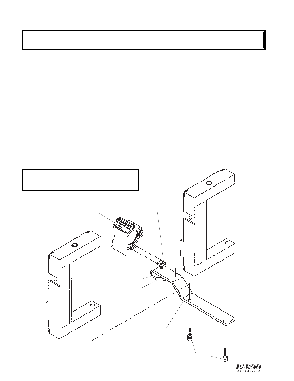
Installing the Photogate Mounting Bracket
The PASCO Model ME-6821 Photogate Mounting
Bracket is an optional accessory to the PASCO Projectile
Launchers. It attaches to the front of the launcher and
holds one or two photogates in parallel for measuring the
muzzle velocity of the ball.
Setup procedure
➀ Loosen the thumbscrew of the Photogate Mounting
Bracket.
➁ Align the bracket assembly with the front of the Pro-
jectile Launcher and slide the square nut down the
groove of the barrel until the dowel pin enters the
groove.
(The dowel pin acts as an alignment guide and must
enter the groove for proper alignment of the bracket.)
➤ NOTE: The flat side of the square nut must face the
inside of the projectile launcher groove as shown.
Projectile
Launcher
➂ Slide the Photogate Mounting Bracket to the desired
position and tighten the thumbscrew to secure.
➃ Unscrew the small rod clamp from the Photogate
Head. (Save the clamp assembly for later use.)
➄ Attach each photogate to the Mounting Bracket with
one of the 6-32x3/8" nylon thumbscrews included
with the bracket assembly.
➅ Slide the Mounting Bracket back until the photogate
nearest to the barrel is as close to the barrel as possible
without blocking the beam.
➆ When storing the launcher, the Photogate Mounting
Bracket need not be removed. It can be slid back
along the barrel with or without the photogates in
place, making as compact a package as possible.
2nd Photogate
square
nut
Head (optional)
Photogate
Head
washer
thumb
screw
Photogate Mounting
6
Bracket
nylon thumb
screw
®
012-05375B Ballistic Pendulum/Projectile Launcher
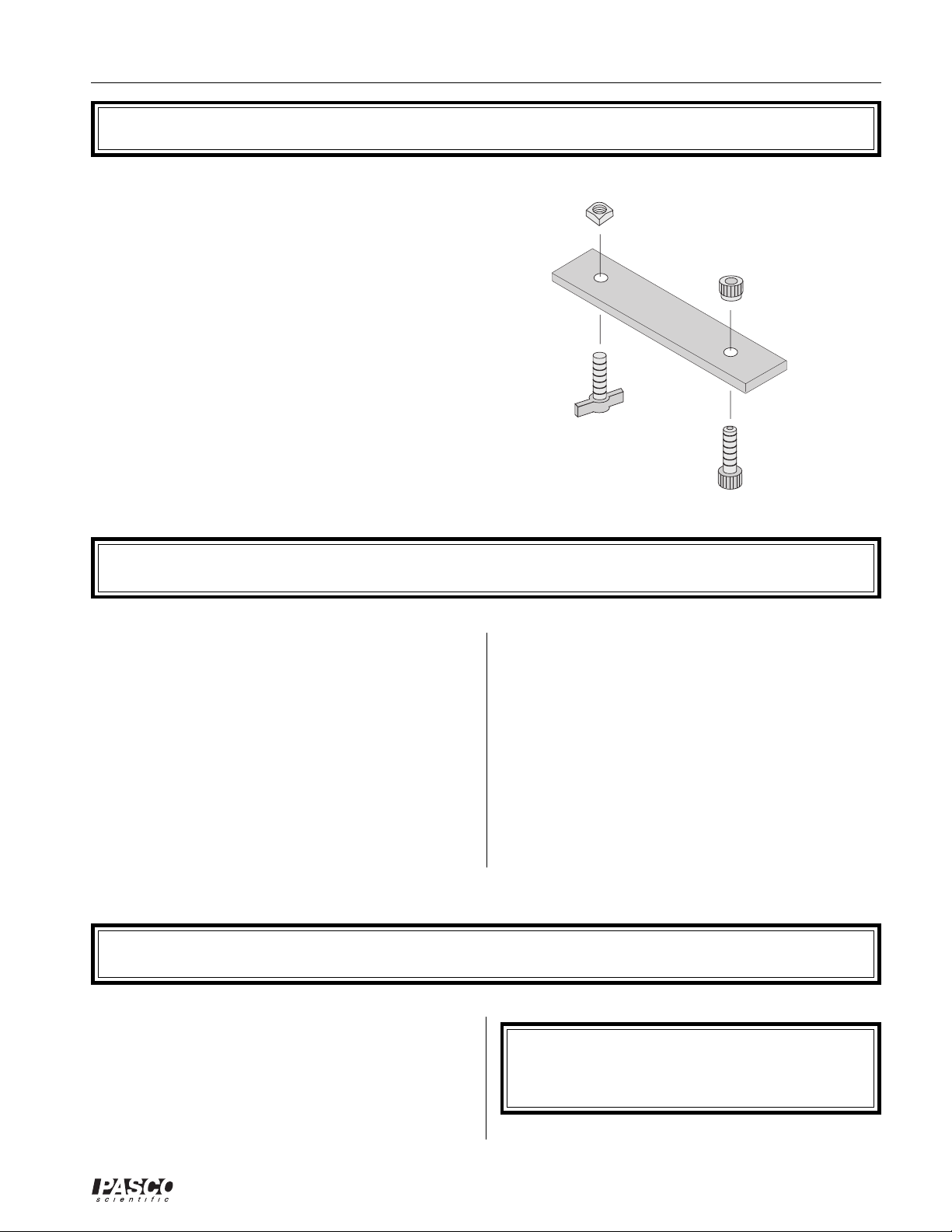
Installing the 2-Dimensional Collision Attachment
Introduction
The two dimensional collision attachment consists of 2
screws, 2 nuts, and a flat plastic bar. It is used with the
Projectile Launcher to hold a second ball in front of the
muzzle so the launched ball will collide with the second
ball, creating a 2-dimensional collision.
Assembly
To assemble the collision attachment , insert the screws
through the holes and secure with the nuts as shown below.
To mount the collision attachment to the Launcher the
square nut slides into the T-shaped channel on the bottom
of the barrel. (See Experiment Figure 6.2 )
Expectations for the Projectile Launcher
The following are helpful hints and approximate values
you may find useful:
➀ The muzzle speed will vary slightly with angle. The
difference between muzzle speed when shot horizontally versus vertically can be anywhere from zero to
8%, depending on the range setting and the particular
launcher.
➁ The scatter pattern may not be smaller on the short
range than on the long range as might be expected because the ball doesn’t seat as well in the piston at low
accelerations.
square
nut
thumb nut
➂ Although the muzzle end of the Projectile Launcher
doesn’t change height with angle, it is about 30 cm
(12 inches) above table level, so if it is desired to use
the simple range formula, it is necessary to launch to a
table that is at the same height as the muzzle.
➃ The scatter pattern is minimized when the Projectile
Launcher base is securely clamped to a sturdy table.
Any wobble in the table will show up in the data.
➄ The angle of inclination can be determined to within
one- half of a degree.
Expectations for the Ballistic Pendulum
➀ Angles reached should be repeatable to within half a
degree.
➁ Overall error in measurement of ball velocity should
not exceed 2.5% (exact method) or 10% (approximate
method).
®
➤ NOTE: Adjustable leveling feet are not neces-
sary for good results. Small deviations from the
horizontal will not cause significant error.
7

Ballistic Pendulum/Projectile Launcher 012-05375B
8
®
012-5375B Ballistic Pendulum/Projectile Launcher
x
ν
1
x
Experiment 1: Projectile Motion
EQUIPMENT NEEDED:
- Projectile Launcher and plastic ball
- Plumb bob
- meter stick
- carbon paper
- white paper
Purpose
The purpose of this experiment is to predict and verify the range of a ball launched at an angle.
The initial velocity of the ball is determined by launching it horizontally and measuring the range
and the height of the launcher.
Theory
To predict where a ball will land on the floor when it is launched off a table at some angle above
the horizontal, it is necessary to first determine the initial speed (muzzle velocity) of the ball. This
can be determined by launching the ball horizontally off the table and measuring the vertical and
horizontal distances through which the ball travels. Then the initial velocity can be used to
calculate where the ball will land when the ball is launched at an angle.
➤➤
➤ NOTE: For best results, see the notes on "Repeatable Results" in the Introduction.
➤➤
HORIZONTAL INITIAL VELOCITY:
For a ball launched horizontally off a table with an initial speed, vo, the horizontal distance
travelled by the ball is given by
assumed to be negligible.
The vertical distance the ball drops in time t is given
The initial velocity of the ball can be determined by measuring x and y. The time of flight of the
ball can be found using:
and then the initial velocity can be found using
INITIAL VELOCITY AT AN ANGLE:
To predict the range, x, of a ball launched with an initial velocity at an angle, θ, above the horizontal, first predict the time of flight using the equation for the vertical motion:
y = y0+ v0sinθt –
where yo is the initial height of the ball and y is the position of the ball when it hits the floor. Then
, where t is the time the ball is in the air. Air friction is
= v0t
y =1gt
t =
gt
2
2y
g
x
=
0
2
2
.
use
= v0cosθt
to find the range.
Setup
➀ Clamp the Projectile Launcher to a sturdy table near one end of the table.
➁ Adjust the angle of the launcher to zero degrees so the ball will be launched horizontally.
®
9

Ballistic Pendulum/Projectile Launcher 012-05375B
Procedure
Part A: Determining the Initial Velocity of the Ball
➀ Put the plastic ball into the Projectile Launcher and cock it to the long range position. Launch
one ball to locate where the ball hits the floor. At this position, tape a piece of white paper to
the floor. Place a piece of carbon paper (carbon-side down) on top of this paper and tape it
down. When the ball hits the floor, it will leave a mark on the white paper.
➁ Fire about ten shots.
➂ Measure the vertical distance from the bottom of the ball as it leaves the barrel (this position is
marked on the side of the barrel) to the floor. Record this distance in Table 1.1.
➃ Use a plumb bob to find the point on the floor that is directly beneath the release point on the
barrel. Measure the horizontal distance along the floor from the release point to the leading
edge of the paper. Record in Table 1.1.
➄ Measure from the leading edge of the paper to each of the ten dots and record these distances
in Table 1.1.
➅ Find the average of the ten distances and record in Table 1.1.
➆ Using the vertical distance and the average horizontal distance, calculate the time of flight and
the initial velocity of the ball. Record in Table 1.1.
Part B: Predicting the Range of the Ball Launched at an Angle
➀ Adjust the angle of the Projectile Launcher to an angle between 30 and 60 degrees and record
this angle in Table 1.2.
➁ Using the initial velocity and vertical distance found in the first part of this experiment,
assume the ball is launched at the new angle you have just selected and calculate the new time
of flight and the new horizontal distance. Record in Table 1.2.
➂ Draw a line across the middle of a white piece of paper and tape the paper on the floor so the
line is at the predicted horizontal distance from the Projectile Launcher. Cover the paper with
carbon paper.
➃ Launch the ball ten times.
➄ Measure the ten distances and take the average. Record in Table 1.2.
Analysis
➀ Calculate the percent difference between the predicted value and the resulting average distance
when launched at an angle.
➁ Estimate the precision of the predicted range. How many of the final 10 shots landed within
this range?
10
®

012-5375B Ballistic Pendulum/Projectile Launcher
Table 1.1 Determining the Initial Velocity
Vertical distance = _____________ Horizontal distance to paper edge = ____________
Calculated time of flight = _________ Initial velocity = _______________
Trial Number Distance
1
2
3
4
5
6
7
8
9
10
Average
Total Distance
Table 1.2 Confirming the Predicted Range
Angle above horizontal = ______________ Horizontal distance to paper edge = ____________
Calculated time of flight = _____________ Predicted Range = ____________
Trial Number Distance
1
2
3
4
5
6
7
8
9
10
Average
Total Distance
®
11

Ballistic Pendulum/Projectile Launcher 012-05375B
12
®
012-5375B Ballistic Pendulum/Projectile Launcher
x
Experiment 2: Projectile Motion Using Photogates
EQUIPMENT NEEDED
- Projectile Launcher and plastic ball -Photogate Mounting Bracket
- (2) Photogate Heads - computer
- plumb bob - meter stick
- carbon paper - white paper
Purpose
The purpose of this experiment is to predict and verify the range of a ball launched at an angle.
Photogates are used to determine the initial velocity of the ball.
Theory
To predict where a ball will land on the floor when it is launched off a table at some angle above
the horizontal, it is necessary to first determine the initial speed (muzzle velocity) of the ball. This
can be determined by launching the ball and measuring the speed using photogates. To predict the
range, x, of the ball when it is launched with an initial velocity at an angle q, above the horizontal,
first predict the time of flight using the equation for the vertical motion:
y = y0+ v0sinθt –1gt
where yo is the initial height of the ball and y is the position of the ball when it hits the floor. Then
use
= v0cosθt
➤➤
➤ NOTE: For best results, see the notes on "Repeatable Results" in the Introduction.
➤➤
to find the range.
2
Setup
➀ Clamp the Projectile Launcher to a sturdy table near one end of the table.
➁ Adjust the angle of the Projectile Launcher to an angle between 30 and 60 degrees.
➂ Attach the photogate bracket to the launcher and attach two photogates to the bracket. Plug the
photogates into a computer or other timer.
Procedure
PART A: D et erm ini ng t he In iti al Ve loc it y of t he Ba ll
➀ Put the plastic ball into the Projectile Launcher and cock it to the long range position.
➁ Run the timing program and set it to measure the time between the ball blocking the two
photogates.
➂ Launch the ball three times and take the average of these times. Record in Table 2.1.
➃ Using that the distance between the photogates is 10 cm, calculate the initial speed and record it in
Table 2.1.
®
13
Ballistic Pendulum/Projectile Launcher 012-05375B
Table 2.1 Initial Speed
Trial Number Time
1
2
3
Average Time
Initial Speed
PART B : Pr ed ic ti ng t he Ra ng e o f the Bal l L au nch ed at an A ngle
➀ Keep the angle of the Projectile Launcher at the chosen angle.
➁ Measure the vertical distance from the bottom of the ball as it leaves the barrel (this position
is marked on the side of the barrel) to the floor. Record this distance in Table 2.2.
➂ Using the initial velocity and vertical distance found, assume the ball is launched at the angle
you have selected and calculate the time of flight and the horizontal distance. Record in Table
2.2.
➃ Draw a line across the middle of a white piece of paper and tape the paper on the floor so the
line is at the predicted horizontal distance from the Projectile Launcher. Cover the paper with
carbon paper.
➄ Launch the ball ten times.
➅ Measure the ten distances and take the average. Record in Table 2.2.
Analysis
➀ Calculate the percent difference between the predicted value and the resulting average
distance when launched at an angle.
➁ Estimate the precision of the predicted range. How many of the final 10 shots landed within
this range?
14
®
 Loading...