

Page 1
Instruction Manual
Manual No. 012-08546A
Pulley Demonstration
System
Model No. SE-8685
Page 2

Pulley Demonstration System Model No. SE-8685
Table of Contents
Equipment List........................................................... 3
Introduction ............................................................. 4
Equipment Setup ........................................................ 5
I. Assembling the Frame................................................................................................................5
II. Sample Setup Options (Hanging Pulleys on the Frame)...........................................................5
A. Set up a Single Pulley on the Frame..................................................................................... 5
B. Set up a Double Pulley on the Frame....................................................................................6
C. Set up One or More Triple-Tandem Pulley(s) on the Frame ................................................6
D. Set up One or More Quadruple Pulley(s) on the Frame........................................................7
E. Set up a Four-Step Pulley on the Frame................................................................................7
Suggested Experiments ................................................. 8
Experiment 1: Mechanical and Force Differences between a Single and Double Pulley..............8
Experiment 2: Determining the Work/Energy of a Pulley System..............................................10
Experiment 3: Discovering the Mechanics of a Wheel and Axle (4-Step Pulley).......................11
Sample Data/Results................................................... 12
Appendix A: Specifications............................................ 13
Appendix B: Technical Support ....................................... 14
Appendix C: Copyright and Warranty Information .................. 14
2
®
Page 3
Model No. SE-8685 Pulley Demonstration System
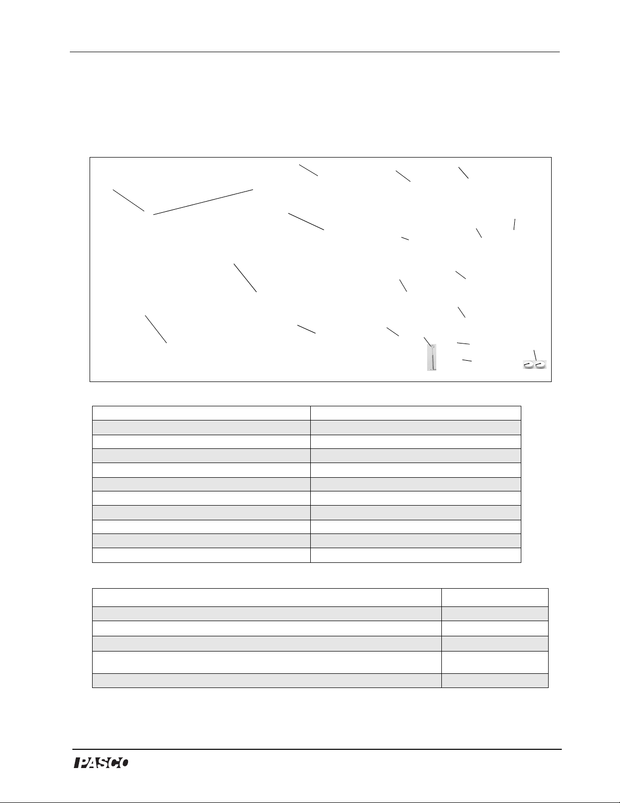
Pulley Demonstration System
Model No. SE-8685
4
3
2
1
Included Equipment
1. Base, 20 cm x 81 cm (1) 11. Slotted mass, 500 grams (1)
2. Aluminum rods, 81 cm (3) 12. Slotted mass, 200 grams (4)
3. Clamps, 90-degree angle (2) 13. Slotted mass, 100 grams (4)
4. Hook collars (8) 14. Slotted mass, 50 grams (2)
5. Single pulley (8) 15. Slotted mass, 20 grams (2)
6. Triple-tandem pulley (2) 16. Slotted mass, 10 grams (2)
7. Quadruple parallel pulley (2) 17. Slotted mass hanger, 50 grams (5)
8. Four-step differential pulley with head(1) 18. Slotted mass hanger, 20 grams (1)
9. Tightening rod (1) 19. Slotted mass hanger, 10 grams (1)
10. Nylon cord spool, 100 yards (1)
5
17
6
10
11
18
19
7
9
12
13
14
15
8
16
Additional Equipment Required
Metric Spring Scale, 20 N
Force Sensor
Rotary Motion Sens or
Any PASCO interface (
A computer
ScienceWorkshop
® or PASPORT™ interface)
Model Number
PS-2104* or CI-6746**
PS-2120* or CI-6538**
* PASCO’s PASPORT sensors (with PS- prefix) require a PASPORT interface for operation.
**PASCO’s
ScienceWorkshop
®
sensors (with CI- prefix) require a
ScienceWorkshop
interface for operation.
SE-8718
Various
(See PASCO cata log)
NA
3
Page 4

Pulley Demonstration System
Introduction
The Pulley Demonstration System (SE-8685) is designed for both the student and the teacher.
Its ease of use is suited for students learning the basics of mechanical advantage with pulley
applications. The various kinds of pulleys and accessories make it the ideal pulley
demonstration tool.
Figure 1: Pulley Demonstration System
PASCO offers a variety of sensors and equipment for measuring force, rotary motion, and
work or energy. PASCO's Metric Spring Scales (SE-8713 to SE-8718) provide an
economical way to instrument the Pulley Demonstration System for measurements of force.
For real-time data collection, and more accuracy and precision, use PASCO's Force and
Rotary Motion Sensors with a computer interface and the Pulley Demonstration System to
demonstrate work/energy theory.
4
®
Page 5
Equipment Setup
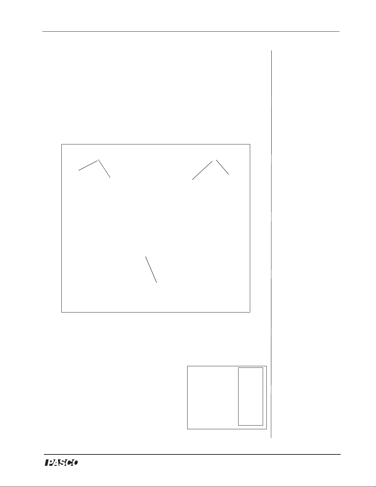
I. Assembling the Pulley Frame
a) Set the base on a sturdy, level surface. b) Thread the two support
rods to the base. c) Fasten both clamps to the top of the support rods.
d) Attach only one side of the horizontal rod to a clamp, so that one
end is free and the other is fixed. e) Slide the hook collars down the
free end of the horizontal rod. f) Secure the free end. g) Tighten the
hook collars using the top screws.
Pulley Demonstration System
Fixed end
clamp
Base
Figure 1: Assembled Frame
clamp
Free end
II.Sample Setup Options (Hanging Pulleys on the Frame
A. Set up a Single Pulley on the Frame
a) Hang the metal hook on the top of the
single pulley on the hook collar. b) Tie string
to a mass hanger and loop it up and around the
pulley. c) Add weight to the mass hanger.
[Note: The free end is for pulling and
attaching measuring devices (i.e. spring scale
or Force Sensor) to measure the force.]
®
Figure 2:
Single Pulley
5
Page 6

Pulley Demonstration System
B. Set up a Double Pulley on the Frame
a) Hang a single pulley to a hook
collar. b) Tie string to another hook
collar. c) Loop the string underneath
another single pulley. d) Attach a
mass hanger to the lower pulley's
lower hook. e) Loop the string up and
over the top pulley.
[Note: The free end is for pulling and
attaching measuring devices (i.e.
spring scale or Force Sensor) to
measure the force.]
C. Set up One or More Triple-Tandem Pulley(s) on the Frame
Figure 3: Double Pulley
Set up for one triple-tandem
pulley: a) Place a hook collar on the
frame and adjust the top screw to
tighten. b) Hang the upper metal
hook of the triple-tandem pulley onto
the hook collar. c) Loop a separate
piece of string around each ring and
hook to a mass hanger. d) Add mass.
A variety of setups can be used,
depending upon your experiment.
Figure 4a: One
Triple-Tandem
Pulley
Setup for two triple-tandems
together: a) Hang one triple-tandem
on the frame and hold a second tripletandem underneath. b) Loop the
string on the lower hook of the upper
Figure 4b: Two
Triple-Tandems
pulley and continue to string in the
following direction and sequence: i) down and around the smallest ring on
the lower pulley, ii) up and around the smallest ring on the upper pulley, iii)
down and around the medium ring on the lower pulley, iv) up and around the
medium ring on the upper pulley, v) down and around the large ring on the
lower pulley, vi) up and around the large ring on the upper pulley, vii)
Attach a mass hanger to the string hanging from the upper pulley and add
mass. viii) Hook a mass hanger to the lower pulley and add weight to
balance.
6
®
Page 7

D. Set up One or More Quadruple Pulley(s) on the Frame
Set up for one quadruple
pulley: a) Attach a hook collar
to the frame and tighten. b)
Hang the quadruple pulley on
the hook collar. c) Loop a
separate piece of string around
each ring and hook to a mass
hanger. d) Add mass. e) Use
Figure 5a:
Quadruple
pulley
the free end of the string for
pulling or attaching measuring
devices. (Note: A variety of
setups can be used, depending
upon your experiment.)
Set up for two quadruple
Figure 5b:
Setup with
two quadruple
pulleys
pulleys: For this setup, have a
lab partner available to hold
the lower pulley while you
string the pulleys. To string,
tie a knot on the hook of the upper pulley and string in the following
direction and sequence (Note: Keep all strings parallel (not crossed):
Pulley Demonstration System
i) around the outside rung of the lower pulley, ii) up and around the
outside rung of the upper pulley, iii) down and around the third rung on
the lower pulley, iv) up around the third rung on the upper pulley,
v) down and around the second rung on the lower pulley, vi) up and
around the second rung on the upper pulley, vii) down and around the
inside rung on the lower pulley, vii i) down and around the first rung on
the upper pulley, viv) Hook string from the upper pulley to a mass
hanger and add weight. x) Add weight to the lower pulley.
E. Set up a Four-Step Pulley on the Frame
a) Fasten the 90° clamp to a vertical rod. b) Attach the four-step
pulley to the 90° clamp. c) String
each rung separately. d) Add mass
hangers and masses to balance.
Figure 6a:
Setup for a
Four-Step
Pulley
®
7
Page 8

Pulley Demonstration System
Suggested Experiments/Demonstrations
Experiment 1: Mechanical and Force Differences between a
Single Pulley and Double Pulley
Equipment required (without
computer):
Pulley Demonstration System
(SE-8685)
Two Spring Scales (SE-8718) Computer Interface (1
Measuring tape (PM-8761) DataStudio software
*PASCO’s PASPORT sensors (with PS- prefix) re quire a PASPORT interf ace fo r operation .
PASCO’s
interface for operation.
ScienceWorkshop
sensors (with CI- prefix) require a
Optional equipment (for use with
computer interface):
Two Force Sensors (CI-6746) or
(PS-2104)
ScienceWorkshop
or 1-2 PASPORT)*
ScienceWorkshop
Basic Procedure:
1. Set up a double pulley and a
single pulley each with a 200 g
mass.
2. Simultaneously, pull the string
of each from the same vertical
height down to the base.
3. Observe that the mass of the
single pulley rises twice as high
as the double pulley with twice
the effort or force.
4. Optional step: Measure the force
of each pulley using either two
Newton Spring scales or two
Force Sensors (See descriptions
a) and b) that follow).
8
Figure 1.1: Single pulley vs.
double pulley
®
Page 9

a) Measure the Pulley Force with the Newton Spring Scale
Pulley Demonstration System
Attach Newton spring scales to
spring
scale
the string on each pulley and
quantitatively discover that the
force exerted for the double
pulley decreases by a factor of
2, while the amount of string
that is pulled increases by the
same factor. Prove that the
number of pulleys relates to
this factor. Show students that
increasing the number of
pulleys increases the mechanical advantage. Discuss the fact
that the amount of work done
is the same in either pulley.
b) Measure the Pulley Force with a Force Sensor and a Computer Interface
Figure 1.2: Measuring the force
with spring scales
Instead of Newton Spring Scales, use two PASCO Force Sensors
to observe real-time force changes in DataStudio software.
1. Connect each Force Sensor to a computer interface (ScienceWorkshop or
PASPORT).
Figure 1.3: Connecting the Force Senso r to a PASPORT
interface and to a computer
2. Hang one Force Sensor from the single
pulley and the other Force Sensor from the
double pulley . (To hang, screw a hook to the
top of the Force Sensor and tie the hanging
string through the hook.)
Figure 1.4:
Pulling on
the Force
Sensor
3. In DataStudio, open a graph display and
click the Start button to collect data. As you
pull down on each pulley, force data for
both pulleys will appear in the display.
®
9
Page 10

Pulley Demonstration System
Experiment 2: Determining the Work/Energy of a Pulley System
Equipment required:
Pulley Demonstration System (SE-
8685)
Force Sensor (CI-6746 or PS-2104) Computer Interface (1
DataStudio software
*PASCO’s PASPORT sensors (with PS- prefix) re quire a PASPORT interf ace fo r operation .
PASCO’s
interface for operation.
ScienceWorkshop
sensors (with CI- prefix) require a
Rotary Motion Sensor (CI-6538 or PS-
2120)
ScienceWorkshop
or 1-2 PASPORT)*
ScienceWorkshop
Students can quantitatively find the work done on a pulley system by using
PASCO's Rotary Motion Sensor simultaneously with a Force Sensor.
1. Attach a hook collar and
clamp a Rotary Motion
Sensor to the horizontal
rod.
2. Tie one end of string to
the hook collar and loop
the string underneath a
pulley. Hang a mass
from this pulley.
Figure 2.1
3. Loop the remaining
string around the inside
groove of the Rotary
Figure 2.1-3: Setup
for Experiment 2
Figure 2.2
Motion Sensor.
Figure 2.3
4. Tie the other end of the
string to the Force Sensor.
5. In DataStudio, click the Start button and pull on the Force Sensor. The
work done can be calculated by finding the area in a Force versus Position
graph.
Alternatively , students can compare the work done on just one pulley. Hang
the same mass from just the Rotary Motion Sensor. Pull the Force Sensor
until the work done is the same as with two pulleys. Students will find that
the force applied doubles while the distance pulled is decreased by half.
10
Note: T o cr eate a For ce
vs. Position graph: In
DataStudio’s Experiment
Setup window , go to the
Rotary Motion Sensor and
click the Linear Position
option. From the Data
list, drag the position icon
over the x-axis in the
Graph display.
®
Page 11

Pulley Demonstration System
Experiment 3: Discovering the Mechanics of a Wheel and Axle
(4-Step Pulley)
Equipment required:
Pulley Demonst ration System
(SE-8685)
Calipers (SF-8711) or measuring
tape (PM-8761)
1. Have students measure the diameters of the grooves of the pulley. (If
calipers or a meauring tape is not available, see the Specifications in
Appendix A.)
2. Loop string counterclockwise
around the smallest groove of
the 4-step pulley until there is
enough friction for the string to
support a large mass.
3. Choose one of the other
grooves and loop enough
string clockwise until it can
support some mass.
4. Have the students experiment
with the amount of mass that
balances the system.
5. Ask students to calculate the
ratio between the masses and
compare this value to the ratio
of the diameters of the
grooves. Students should find
Figure 3: Setup with Wheel and
Axle
that the ratio of the diameters
of the grooves is identical to the ratio of the masses.
®
11
Page 12

Pulley Demonstration System
Sample Data/Results
Experiment 1 Results: Mechanical Force Differences in Single Pulley vs.
Double Pulley
Force for single pulley
Force for double pulley
Experiment 2 Results:Measuring the Work/Energy of a Pulley System
Work for one pulley
Work for two pulleys
Experiment 3 Results: Discovering the Mechanics of a Wheel and Axle (4Step Pulley)
Groove 1: diameter = 2.0 cm; mass = 10 g
Groove 4: diameter = 6.0 cm; mass = 30 g
Ratios: diameters=1/3; masses=1/3
12
®
Page 13

Appendix A: Specifications
Pulleys Specifications:
Single pulley: circumference: 15.4 cm; diameter: 4.9 cm
Triple-tandem pulley: small pulley: circumference: 7.9 cm ;
diameter: 2.5 cm
medium pulley: circumference: 11.6 cm;
diameter: 3.7 cm
large pulley: circumference: 15.4 cm;
diameter: 4.9 cm
Quadruple pulley: pulley circumference: 15.4 cm;
diameter: 4.9 cm
Four-step pulley: step 1 groove: 6.28 cm circumference;
2.0 cm diameter
step 2 groove: 9.42 cm circumference;
3.0 cm diameter
step 3 groove: 12.56 circumference;
4.0 cm diameter
step 4 groove: 18.84 circumference:
6.0 cm diameter
Pulley Demonstration System
Slotted masses: 10 g, 20 g, 50 g, 100 g, 200 g, 500 g
®
13
Page 14

Pulley Demonstration System
Appendix B: Technical Support
For assistance with the SE-8685 or any other PASC O products, contact
PASCO as follows:
Address: PASCO scientific
10101 Foothills Blvd.
Roseville, CA 95747-7100
Phone: (916) 786-3800
FAX: (916) 786-3292
Web: www.pasco.com
Email: techsupp@pasco.com
Appendix C: Copyright and Warranty Information
Copyright Notice
The PASCO scientific 012-08546A Pulley Demonstration System Manual is copyrighted and
all rights reserved. However, permission is granted to non-profit educational institutions for
reproduction of any part of the 012-08546A Pulley Demonstration System Manual, providing
the reproductions are used only for their laboratories and are not sold for profit. Reproduction
under any other circumstances, without the written consent of PASCO scientific, is
prohibited.
Limited Warranty
PASCO scientific warrants the product to be free from defects in materials and workmanship
for a period of one year from the date of shipment to the customer. PASCO will repair or
replace, at its option, any part of the product which is deemed to be defective in material or
workmanship. The warranty does not cover damage to the product caused by abuse or
improper use. Determination of whether a product failure is the result of a manufacturing
defect or improper use by the customer shall be made solely by PASCO scientific.
Responsibility for the return of equipment for warranty repair belongs to the customer.
Equipment must be properly packed to prevent damage and shipped postage or freight
prepaid. (Damage caused by improper packing of the equipment for return shipment will not
be covered by the warranty.) Shipping costs for returning the equipment after repair will be
paid by PASCO scientific.
14
®
 Loading...