

Page 1
Includes
Teacher's Notes
and
Typical
Experiment Results
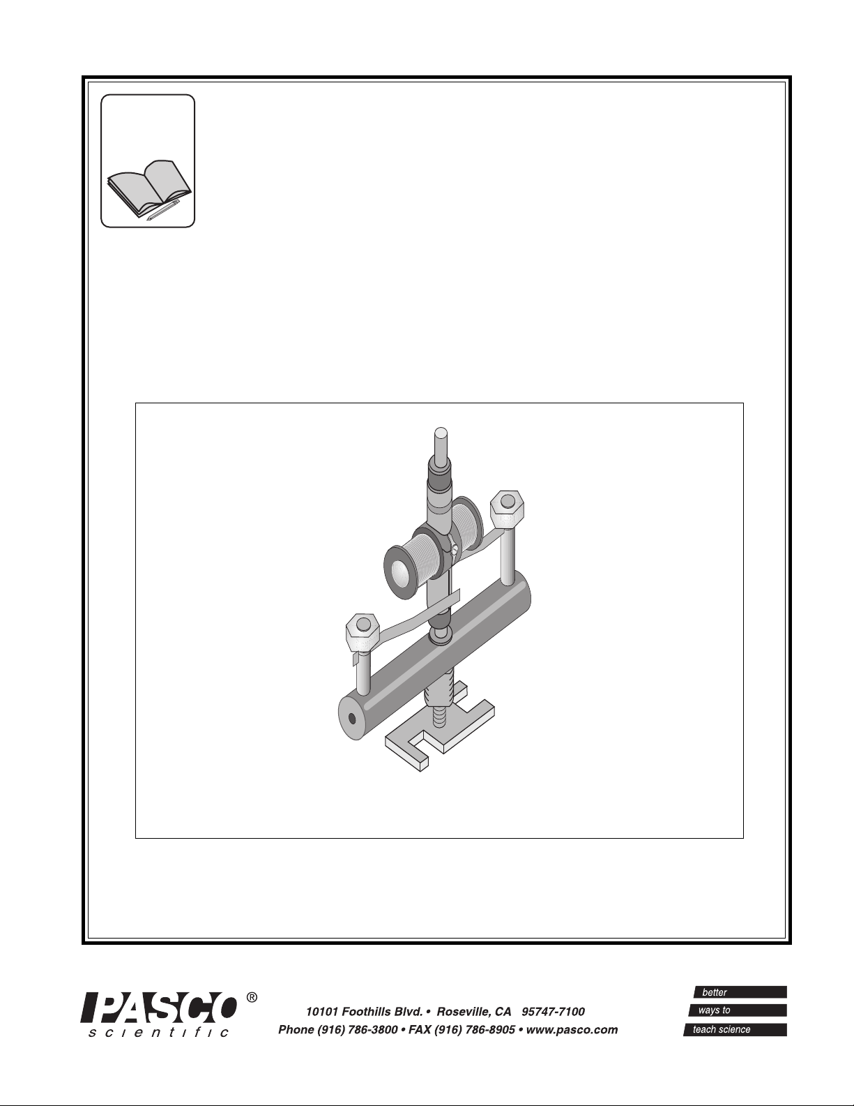
MOTOR ACCESSORY
Instruction Manual and
Experiment Guide for the
PASCO scientific
Model SE-8657
012-06247A
8/96
© 1996 PASCO scientific $7.50
Page 2

Page 3
012-06247A Motor Accessory
T able of Contents
Section...................................................................................................... Page
Copyright and Warranty, Equipment Return................................................... ii
Introduction ......................................................................................................1
Equipment ........................................................................................................1
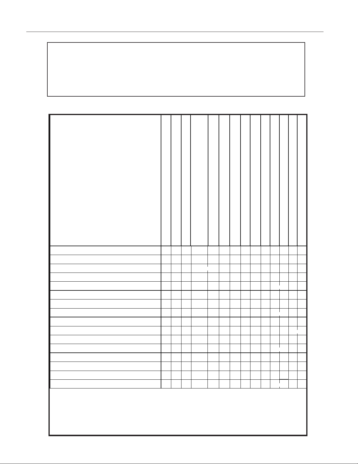
Table 1. Equipment Options for Experiments 1 - 4 ..........................................2
Operation .........................................................................................................3
Assembly—Motor Accessory onto the Variable Gap Magnet .........................4
Assembly—Motor Accessory onto the Coils and Cores Set ............................5
Suggested Uses ................................................................................................6
Experiment 1: Operation of the DC Motor......................................................7
Experiment 2: Operation of AC and DC Generators ....................................13
Experiment 3: Operation of an AC Synchronous Motor ...............................19
Experiment 4: Operation of the Universal Motor ..........................................25
Teacher’s Guide .............................................................................................29
Technical Support ..........................................................................................34
®
i
Page 4
Motor Accessory 012-06247A
Copyright, Warranty and Equipment Return
Please—Feel free to duplicate this manual
subject to the copyright restrictions below.
Copyright Notice
The PASCO scientific SE-8657 Motor Accessory
manual is copyrighted and all rights reserved. However, permission is granted to non-profit educational
institutions for reproduction of any part of the manual
providing the reproductions are used only for their
laboratories and are not sold for profit. Reproduction
under any other circumstances, without the written
consent of PASCO scientific, is prohibited.
Limited Warranty
PASCO scientific warrants the product to be free from
defects in materials and workmanship for a period of one
year from the date of shipment to the customer. PASCO
will repair or replace, at its option, any part of the product
which is deemed to be defective in material or workmanship. The warranty does not cover damage to the
product caused by abuse or improper use. Determination of whether a product failure is the result of a
manufacturing defect or improper use by the customer
shall be made solely by PASCO scientific. Responsibility for the return of equipment for warranty repair
belongs to the customer. Equipment must be properly
packed to prevent damage and shipped postage or
freight prepaid. (Damage caused by improper packing of the equipment for return shipment will not be
covered by the warranty.) Shipping costs for returning the equipment, after repair, will be paid by
PASCO scientific.
Equipment Return
Should the product have to be returned to PASCO
scientific for any reason, notify PASCO scientific by
letter, phone, or fax BEFORE returning the product.
Upon notification, the return authorization and
shipping instructions will be promptly issued.
ä
NOTE: NO EQUIPMENT WILL BE
ACCEPTED FOR RETURN WITHOUT AN
AUTHORIZATION FROM PASCO.
When returning equipment for repair, the units
must be packed properly. Carriers will not accept
responsibility for damage caused by improper
packing. To be certain the unit will not be
damaged in shipment, observe the following rules:
➀ The packing carton must be strong enough for the
item shipped.
➁ Make certain there are at least two inches of
packing material between any point on the
apparatus and the inside walls of the carton.
➂ Make certain that the packing material cannot shift
in the box or become compressed, allowing the
instrument come in contact with the packing
carton.
Credits
Author: Jim Housley
Editor: Sunny Bishop
Address: PASCO scientific
10101 Foothills Blvd.
Roseville, CA 95747-7100
Phone: (916) 786-3800
FAX: (916) 786-3292
email: techsupp@pasco.com
web: www.pasco.com
ii
®
Page 5
012-06247A Motor Accessory
Introduction
The PASCO SE-8657 Motor Accessory transforms the
PASCO EM-8641 Variable Gap Magnet into a motor
that can operate on alternating or direct current, as well
as a generator that can produce alternating or direct
current. The Motor Accessory also transforms the
PASCO SF-8616 Coils and Cores Set into a universal
Equipment
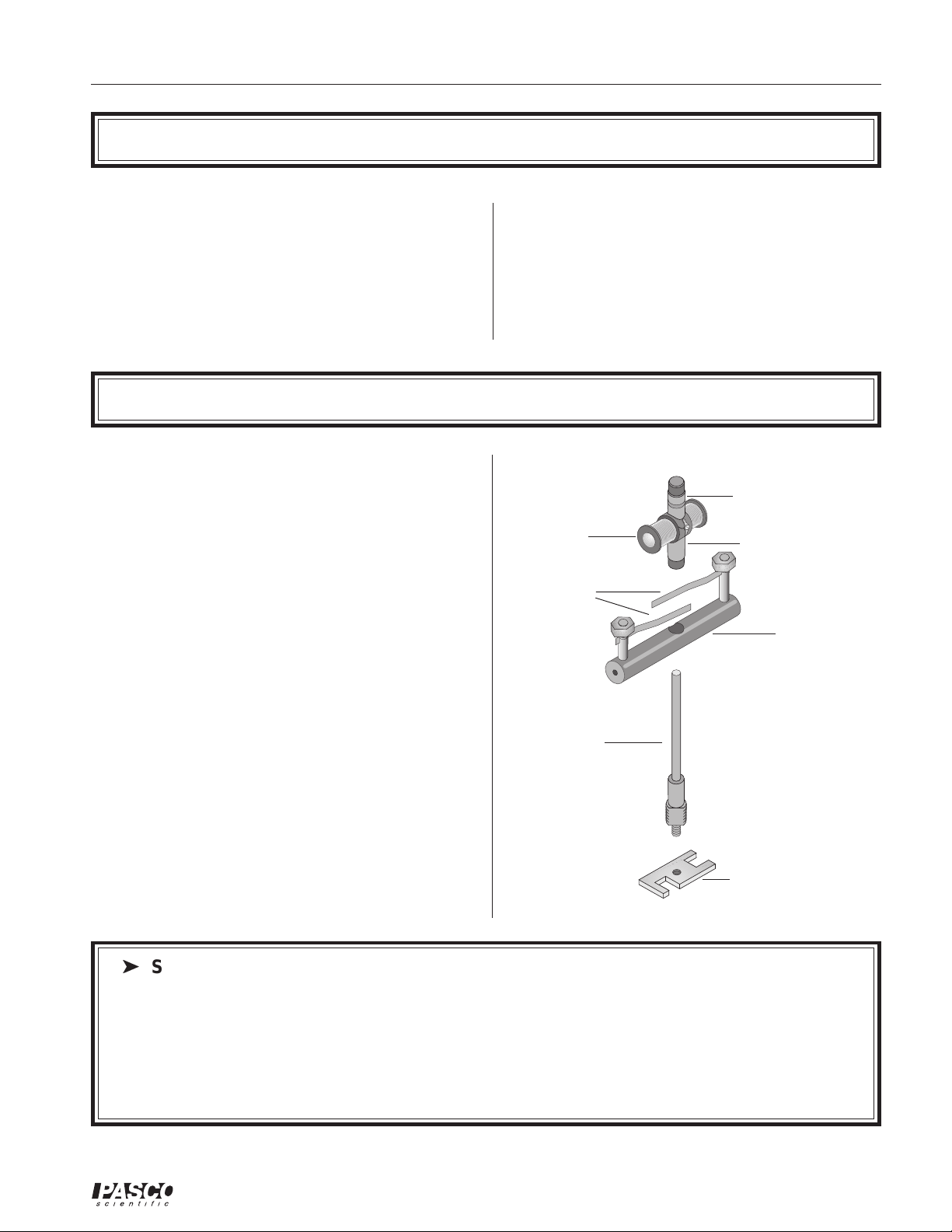
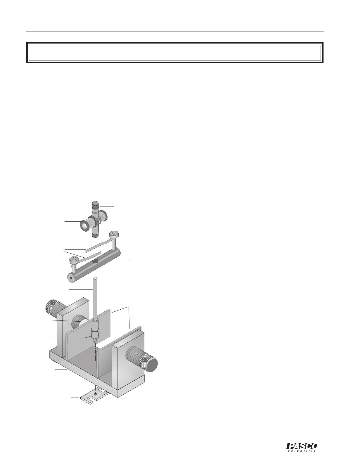
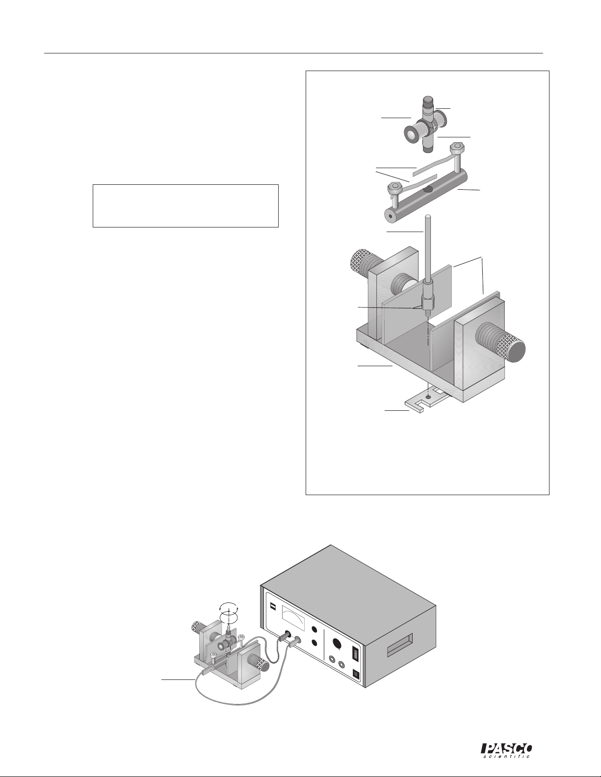
The Motor Accessory includes
- armature with split commutator at one end and a
dual slip-ring commutator at the other
- brush holder
- shaft
- wrench/retaining nut
- maintenance items
motor. Combined with an AC/DC power supply and
sensors for voltage, current, and rotational speed,
these motors allow students to discover key concepts
and relationships concerning motors and electric
current. Students can also explore properties of AC
and DC generators with this apparatus.
dual slip-ring
commutator
armature
brushes
split ring
commutator
brush holder
- manual
- ceramic magnet
shaft
Additional Equipment Required:
- Variable Gap Magnet (EM-8641) or
- Coils and Cores Set (SF-8616)
wrench/
retaining nut
ä
Safety precautions
- Always wear safety goggles when in a room where the Motor Accessory is being used.
- Keep fingers and other objects away from the spinning armature.
- Choose power sources that limit current to not more than one ampere (1.0 A). The motor may overheat
if this current is exceeded or if power is applied continuously, especially if the armature is not rotating.
The motor is intended only for intermittent operation.
- Disconnect any power source whenever the motor is to be left unattended.
®
1
Page 6
Motor Accessory 012-06247A
➤ NOTE: Although the instructions for experiments in this manual are for mechanical setups
with specific PASCO equipment, the experiments in this manual may be set up in a variety of ways,
depending upon the equipment you have available. They can all be done with or without the
PASCO Science
experimental setups. You may be able to substitute other equipment for the PASCO models listed
Workshop computer interface. Table 1 lists the equipment suggested for optional
Table2.xls
in this table.
Table 1. Equipment Options for Experiments 1 - 4
Equipment Options
for Experimental
Setups with the
PASCO SE-8657
Motor Accessory
Experiment Options
Experiment 1: DC Motor
no computer interface
no computer interface
computer interface
computer interface
Experiment 2: AC/DC Generator
no computer interface
computer interface
Experiment 3: Synchronous AC Motor
no computer interface
computer interface
computer interface
Experiment 4: Universal Motor
no computer interface
computer interface
computer interface
Low Voltage DC Power Supply (SE-9720)
Motor Accessory (SE-8657)
Variable Gap Magnet (EM-8641)
xx x
xx x x
xx x x x x
xx x xx
xx x
xx xxx
xx x xx
xx x x x x
xx x xx x
xx x
xx x xx
xx x xx
(SE-9712) or similar*
Coils and Cores Set (SF-8616)
Low Voltage AC/DC Power Supply (SF-9584) *
Power Amplifier (CI-6550A) (CI-6552A)
Digital Function Generator/Amplifier (PI-9587)
Multimeter (e.g. SB-9623) or Ammeter (SF-9569)
Galvanometer (SF-9500) or Multimeter (SB-9623)
OR
Voltage Sensor (CI-6503)
Science Workshop 300 or 500 Interface
Science Workshop 700 or 6500 Interface
Digital Photogate Timer (SF-9215A)
Digital Stroboscope (SF-9211)
OR
OR
OR
OROR
OR
*If your power supply does not have the capability to quantify output current, you will need
to measure it using an ammeter, or preferably, by calculating it from the voltage drop
across a small value series resistor. (This option avoids the potential for damage to a
sensitive ammeter.)
It is important to limit the current to a maximum of 1 A to avoid
damaging the armature.
2
®
Page 7
012-06247A Motor Accessory
Operation
Options for electrical connections
- Banana-style plugs may be inserted into openings
in the ends of the black plastic brush holder.
- Large alligator clips may be attached to the brass
posts that hold the brushes.
- Small alligator clips may be attached directly to
the ends of the brushes where they protrude from
the slits in the brass posts.
Options for Power Sources
It is important to limit the current of the power source
to 1.0 A to avoid damaging the coils of the armature.
Either choose a power supply that can be set to deliver
a maximum current of 1.0 A, or use your power
source connected in series with a multimeter or
ammeter to monitor the output current. (Alternatively, to avoid possible damage to a sensitive
ammeter, you can measure the voltage drop across
a low-value series resistor, such as a 0.51 ohm, 1
watt resistor, and calculate the output current.) You
will also need to adjust and measure the output
voltage, so if your power supply does not have this
capability, you will need a multimeter or voltmeter.
(See Table 1 for specific suggestions for power
sources.)
Starting the motor
- The motor is not self-starting. Immediately after
you apply the power, start the motor manually by
grasping the black plastic bushing at the top of
the armature assembly between your thumb and
forefinger and spinning the armature.
source. This is impractical at frequencies
much above 30 Hz, and some students may
require assistance even a lower frequencies.
Maintenance and Storage
- A small box is provided for storing the parts of
the motor not installed on either the Variable
Gap Magnet or Coils and Cores Set.
- The commutators and brushes will experience
wear, oxidation, and pitting and will require attention from time to time. Rotate the armature
slowly by hand and monitor current flow or
sense the force developed to determine whether
proper contact is occurring between brushes and
commutator. To restore proper operation, clean
the contacts with emery paper or shift the
brushes somewhat to expose new surfaces.
- Careless installation of the armature onto the
shaft might bend the brushes. You can easily
bend them back into their original shape with
finger pressure.
➤ NOTE: If you are using a PASCO CI-
6502A Power Amplifier (for the CI-6500
Interface System), the distorted waveform light
will turn on during operation of the motor, but
no damage is being done to the Power Amplifier; you can ignore the light.
- With the Motor Accessory configured as either a
DC or universal motor, almost any attempt you
make at spinning the armature will result in successfully starting the motor; only the direction of
the spin is important.
- When configured in an AC synchronous mode,
the motor must be spun at a speed that approximately matches the frequency of the power
¨
3
Page 8
Motor Accessory 012-06247A
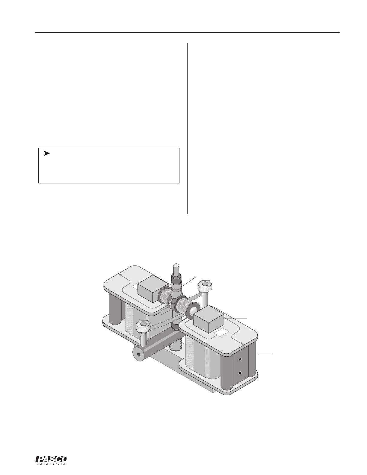
Assembly
Motor Accessory onto the Variable Gap
Magnet
➀ Be sure you have the flat iron pole pieces placed on
the two neodymium magnets of the Variable Gap
Magnet. The larger threaded portion of the shaft
screws easily, without tools, into the threaded hole
in the magnet base. Insert the threaded end of the
shaft from above, screwing it in until 1 mm, or
slightly less, of the threaded portion remains above
the upper surface of the base.
➁ Turn the magnet over and screw the retaining nut
onto the smaller diameter threaded portion of the
dual slip-ring commutator
armature
brushes
shaft
(this end down for
AC motor)
split ring
commutator
(this end down for
DC motor)
brush holder
shaft that protrudes through the bottom of the magnet base. (Note that the retaining nut has a metric
thread, size M6-1.0.) Use firm finger pressure. If
this should prove inadequate, tighten the nut somewhat more with a wrench. If an appropriate wrench
is not at hand, use a heavy metal object to tighten
the nut by tapping the edge of the nut. Do not use
a pole piece of the magnet to tighten the nut because that might mar the finish of the pole piece.
Do not over tighten.
➂ Working from above, press the brush holder onto
the smooth, enlarged portion of the shaft. Apply
increasingly firm pressure equally to each side of
the brush holder while rotating the brush holder
back and forth. If this action loosens the retaining
nut, tighten it more tightly, as described in step 2.
Check to be sure the brush assembly is seated as far
down on the shaft as it will go.
➃ Gently lower the armature onto the shaft. To make
a DC motor, the split ring commutator should be
down; for an AC motor, the dual slip-ring commu-
tator should be down. Carefully rotate the armature back and forth to separate the brushes and allow the commutator to slip down between them. If
necessary, insert a pencil or similar object down
between the brushes. Use only the most delicate
force to avoid bending the brushes and necessitating adjustments or repairs.
flat pole pieces
neodymium
magnet
leave 1mm
exposed at
installation
magnet base
wrench/retaining
nut
Motor AccessoryVariable Gap Magnet Assembly
➄ Adjust the gap of the Variable Gap Magnet so there
is approximately 1 mm of clearance between the
pole pieces and the armature when it is rotated by
hand.
➅ Refer to the instructions included in experiments 1-
4 for details of the electrical connections.
4
¨
Page 9
012-06247A Motor Accessory
Motor Accessory onto the Coils and Cores
Set
➀ Begin with the U-shaped core, with the coils and
any other parts removed. The smaller threaded
portion of the shaft screws easily into the threaded
hole in the core so the shaft is between the poles of
the core. Use the wrench provided to tighten the
shaft by gripping the flats on the larger threaded
portion. The small wrench limits the torque that
can be applied. If an ordinary wrench is used, be
careful not to over tighten.
ä
Note: Do not discard the small wrench; it
is essential as a retaining nut when the Motor
Accessory is used with the Variable Gap
Magnet.
➁ Working from above, press the brush holder
onto the smooth, enlarged portion of the shaft.
Apply increasingly firm pressure equally to each
side of the brush holder while rotating the brush
holder back and forth. If this action loosens the
shaft, tighten it as described in step 1. Check to
be sure the brush assembly is seated as far down
on the shaft as it will go. Orient the brush
holder perpendicular to the base of the Coils and
Cores apparatus.
➂ Place the two 400-turn coils from the Coils and
Cores Set onto the poles of the core.
➃ Gently lower the armature onto the shaft. The split
ring commutator should be down for use as a uni-
versal motor. Carefully rotate the armature back
and forth to separate the brushes and allow the
commutator to slip down between them. If necessary, insert a pencil or similar object between the
brushes to separate them. Use only the most delicate force to avoid bending the brushes and necessitating adjustment or repairs.
400
Motor AccessoryCoils and Cores Assembly
split ring commutator
U-shaped base
400
400-turn coil
¨
5
Page 10
Motor Accessory 012-06247A
Suggested Uses
Operation as a DC motor
The Motor Accessory can be used with the Variable
Gap Magnet to demonstrate the operation of a DC
motor ( Experiment 1). Students can explore relationships between motor speed and voltage, as well as
between direction of armature rotation and polarity,
developing key concepts including: action of the split
ring commutator, dependence of speed on voltage,
dependence of direction of rotation on polarity, righthand rule, and direction of current flow from positive
to negative poles.
Action of AC and DC generators
Spinning the armature by hand while it is connected to
a sensitive DC meter or to the Signal Interface II
shows the action of an AC generator, as well as the
rectifying action of the commutator in a DC generator
(Experiment 2).
Operation of a synchronous AC motor
Operation as a universal motor
The Motor Accessory-Coils and Cores assembly
functions as a universal motor, operating on both AC
and DC power supplies (Experiment 4). Students can
explore the relationships of current direction and direction of the magnetic field, the effect of changes in
voltage and AC current frequency on motor speed, and
the effect of changes in DC voltage on motor speed.
Additional possibilities
The Motor AccessoryVariable Gap Magnet assembly
can be used to determine the speeds of maximum power
and maximum efficiency of a DC motor by varying the
load while simultaneously measuring the speed, torque,
and armature current. In this experiment, you can
measure the motors speed with a photogate or stroboscope.
The Motor AccessoryCoils and Cores assembly also
can be used to demonstrate series-wound, shunt-wound,
and hysteresis-synchronous motor setups.
Coupled with an AC signal supplied by the PASCO PI9587C Digital Function Generator/Amplifier or similar
function generator, the Motor Accessory-Variable Gap
Magnet assemblies will operate in sync with 15 and 30
Hz (and often wider range) signals (Experiment 3).
Students can explore the relationship between AC
voltage and motor speed, as well as between AC current
frequency and motor speed. They can conduct detailed
explorations of the precision of synchronism of AC
current and motor speed with a PASCO SF-9211
Digital Stroboscope or PASCO ME-9215A Digital
Photogate or by observing the stroboscopic effect of an
ordinary fluorescent lamp at selected motor speeds. As
a result, they develop key concepts, including the
independence of AC motor speed and voltage, dependence of AC motor speed on current frequency, and
action of a dual slip-ring commutator.
6
¨
Page 11
012-06247A Motor Accessory
Experiment 1: Operation of the DC Motor
EQUIPMENT NEEDED:
• Motor Accessory • multimeter
• Variable Gap Magnet • patch cords
• low voltage DC power supply, limited to 1 A • small piece of masking tape
Purpose
The purpose of this experiment is to demonstrate the operation of the DC motor in terms of
basic concepts of electromagnetism.
Theory
Setup
The Variable Gap Magnet is a permanent magnet possessing a north pole and a south pole
that interact with the north and south poles of the armature (an electromagnet when connected to an electric current). Like poles repel, while unlike poles attract. The armature
rotates until its north pole is as close as possible to the south pole of the permanent magnet
(and also as far as possible from the north pole). Instead, if the rotational speed of the
armature matches the frequency of the alternating current, the direction of current in the
armature will reverse at that instant, so that the torque continues to act in the original direction.
A better explanation involves an understanding of fields. The variable gap magnet produces a magnetic field that passes through the gap between the pole pieces. When current
passes through the turns of the armature in the presence of the field, forces act to cause a
torque that rotates the armature. Inertia carries the armature past the position of no torque
to the point where the torque would force the armature back in the other direction. However, at that point the commutator reverses the direction of current in the armature so the
torque continues to act in the original direction.
➀ Be sure you have the flat iron pole pieces placed on the two neodymium magnets of the
Variable Gap Magnet. (The iron pole pieces spread the magnetic field over a wider
area.) Screw the larger threaded portion of the shaft into the threaded hole in the magnet
base. Insert the threaded end of the shaft from above, screwing it in until 1 mm, or
slightly less, of the threaded portion remains above the upper surface of the base.
➁ Turn the magnet over and screw the retaining nut onto the smaller diameter threaded
portion of the shaft that protrudes through the bottom of the magnet base. Use firm
finger pressure. Do not over tighten.
¨
7
Page 12
Motor Accessory 012-06247A
➂ Working from above, press the brush
holder onto the smooth, enlarged portion
of the shaft. Apply increasingly firm
pressure equally to each side of the brush
holder while rotating the brush holder
back and forth. If this action loosens the
retaining nut, tighten it more tightly, as
described in step 2.
armature
brushes
dual slip-ring commutator
split ring
commutator
Check to be sure the brush assembly
is seated as far down on the shaft as it
will go.
➃ Gently lower the armature onto the shaft
with the split ring commutator down.
Carefully rotate the armature back and
forth to separate the brushes and allow
the commutator to slip down between
them. If necessary, insert a pencil or
similar object down between the brushes.
Use only the most delicate force to avoid
bending the brushes and necessitating
adjustments or repairs.
➄ Adjust the gap of the Variable Gap
Magnet so there is approximately 1 mm
of clearance between the flat pole pieces
and the armature when it is rotated by
hand.
➅ Connect the positive terminal of the DC
power supply to one end of the brush
holder with a red patch cord by plugging
the banana terminals into each.
brush holder
shaft
flat pole pieces
leave 1mm
exposed at
installation
magnet
base
wrench/retaining
nut
Figure 1. Installation of the Motor Accessory
onto the Variable Gap Magnet
➆ Connect the negative terminal of the DC
power supply to the other end of the
brush holder with a black patch cord.
Do not turn the power on.
wire connected to
the + terminal of the
power supply
Figure 2. Experimental Setup
METER
PUSH FOR
CURRENT
PASCO scientific
MODEL SF-9584 LOW VOLTAGE AC/DC POWER SUPPLY
0 - 24 VOLTS DC OUTPUT
DC VOLTAGE
8 AMP MAX
DC CURENT
8
ADJUST
12
10
8
14
6
16
18
4
ON
AC VOLTAGE ADJUST
ADJUST
2
24
2 - 24 VOLTS AC OUTPUT
6 AMP MAX
20
22
OFF
RESET
¨
Page 13

012-06247A Motor Accessory
Procedure—Part A
➀ Rotate the armature and observe how the segments of the split ring commutator contact the
brushes as the armature turns.
➁ Remove the armature from the shaft by grasping it between your thumb and forefinger and
rotating it back and forth while lifting gently. If necessary, insert a pencil between the
brushes to gently separate them to remove the armature.
➂ Examine the armature closely and imagine current entering one of the split rings from a
brush. Trace the path of the current through the wire to the coil, through the coil, through
the wire to the coil on the opposite side of the armature, through that coil, and through the
wire to the other split ring and into the second brush. By carefully examining the part of
the coils where the wire emerges from the coil, you can determine the direction in which
the wire is wound on the coil (see Figure 3).
Figure 3. Direction of the Wire Winding on the Coil
➃ Holding the armature in one hand, imagine that the brush from the + lead is touching one
of the split rings of the commutator. Follow the wire from the split ring to the right coil of
the armature and note the direction the wire is wound in the coil. Note where the wire
enters the coil and where it exits.
➄ Use the right-hand rule to determine the direction the magnetic field will flow when you
turn on the power: Grasp the coil with your fingers wrapped around the coil in the direction of the current (Figure 4). (Current direction is described by convention as being from
the positive to the negative lead. Note that this is opposite of the direction of electron
movement—see note on page 10) . Your thumb will point in the direction of the field —
that is, toward the north pole of the coil). Put a small piece of tape on the end of the
armature that will be its north pole when you turn on the power.
➅ Follow the wire over to the left coil. Use the right hand rule to find the direction of the
north pole.
Record your observations on Figure 4.
a) In this situation, is the direction of the north pole the same for the right and left coils?
¨
9
Page 14

Motor Accessory 012-06247A
Draw arrows indicating the direction
of current flow.
Indicate which pole: north (N) or south
N
(S).
When you wrap
your fingers in
the direction of
the flow of the
electric current,
your thumb
+
points towards
the north pole of
the magnetic
field.
wire connected to the +
+
terminal of the power
supply
Figure 4. Determining the Direction of the Magnetic Field of the Coil Using the
Right-Hand Rule
➤ Note: Here’s why the direction of conventional current is opposite to that of the
direction of electron flow: In the mid-eighteenth century, Benjamin Franklin suggested the
terms positive and negative, and conjectured that electrical current was the movement of
positive “fluid” from positive to negative regions. Although he understood that it was
equally possible that a negative fluid moves from negative to positive, for more than a
century there was no way to resolve the issue. By convention, scientists agreed to describe
the direction of current as being from positive to negative. Not until 1879 did Edwin H.
Hall show that in metals the current was a negative “fluid”; it remained for J. J. Thompson,
R. A. Millikan, and others to demonstrate the existence of electrons, which are the charge
carriers of this “fluid”. This might seem an argument for changing the convention. But
current doesn’t always travel in metals. In gasses, current consists of electrons traveling in
one direction while positive ions move simultaneously in the opposite direction. In
solutions, current consists of oppositely charged ions traveling in opposing directions.
And in certain semiconductors, it is most useful to think of positive “holes” as being the
charge carriers.
Considering this complexity, scientists have found it most useful to continue the convention begun by Franklin: the “direction” of current is from positive to negative.
10
¨
Page 15

012-06247A Motor Accessory
b ) Both coils surround a single iron core on the armature, and each coil is capable of
temporarily magnetizing the core when electric current is running through it. Do the
actions of the two coils add to create a greater effect or cancel to create a reduced
effect? (Consider your answer to 6a above.)
➆ Turn the armature over 180° and imagine that the brush attached to the + lead is contacting
the other split ring of the commutator. Note the path of the wire from where it is attached
to the split ring to where it enters and exits from the coil on the right side of the armature.
Imagine a current running through the wire and use the right-hand rule to determine the
direction the magnetic field would flow. Is the north pole on the same end of the coil as it
was in step 5?
➇ Follow the wire over to the left coil. Use the right hand rule to find the direction of the
north pole.
a) In this situation, is the direction of the north pole the same for the right and left coils?
b) True or False? When the electric current is on, the two coils become electromagnets
with magnetic fields oriented in the same direction, which turns the armature into a single
electromagnet with its force oriented towards that same direction.
c) True or False: In the DC motor, you cannot determine the direction of the magnetic
field of the armature by determining the direction of the north pole of either of the two
coils.
d) What happens to the location of the armature’s north pole as the brush attached to the
+ lead touches the different sides of the split ring commutator?
e) Can you explain why the current in the armature is alternating, despite the fact that the
motor is supplied with direct current. (Hint: think about your answer to 8d.)
➈ Gently replace the armature onto the shaft with the split ring commutator down. Carefully
rotate the armature back and forth to separate the brushes and allow the commutator to
slip down between them. If necessary, insert a pencil or similar object between the brushes
to separate them. Use only the most delicate force to avoid bending the brushes and
necessitating adjustment or repairs.
Procedure—Part B
➀ Turn on the power. Adjust the output voltage to 6 volts.
➁ Use the small cylindrical ceramic magnet to check your predictions from steps 5 and 6
¨
11
Page 16

Motor Accessory 012-06247A
above. The painted face of the magnet is its North Pole (north-seeking pole). [You can
verify this by hanging the magnet from a thread and observing that the painted face points
toward the North (toward the earth’s north magnetic pole, located in northern Canada).]
With the armature and power supply leads oriented as in Figure 2 and the power turned on,
hold the ceramic magnet near the ends of the armature. If both poles of the ceramic magnet
attract the armature, the pole with the stronger attraction will be the opposite pole.
a) Does the result of this test agree with your predictions in steps 5 and 6?
b) Label each end of the armature in Figure 2 according to whether it is the north or south
pole of the electromagnet.
c) Determine the polarity of the Variable Gap Magnet in the same way. Label its poles “N”
and “S” in Figure 2.
➂ Predict the direction the armature will rotate when you release it from the position of Figure
2.
Will the motor rotate clockwise or counter-clockwise?
If the motor does not start up immediately, try turning it by hand in the predicted direction.
If that fails, try turning it in the opposite direction.
➤ If the motor does not start in either direction, turn off the power and ask your
teacher for help.
➃Turn off the power and reverse the positive and negative leads to the motor. Before turning
the power on, predict the direction of rotation.
a) Will the motor rotate clockwise or counter-clockwise?
Turn the power back on and immediately try spinning the motor to start it. If it doesn’t start,
try spinning it in the other direction.
b) Explain why the armature turns when you turn on the power.
➄ While the motor is running, raise the voltage to approximately 8 volts.
a) What happens to the motor’s rotational speed when you raise the voltage?
b) Is the relationship of the motor’s rotational speed and voltage of the DC current dependent or independent?
12
¨
Page 17

012-06247A Motor Accessory
Experiment 2: Operation of AC and DC Generators
EQUIPMENT NEEDED OPTIONAL EQUIPMENT
• Motor Accessory • Voltage Sensor
• Variable Gap Magnet • computer interface
• multimeter or galvanometer
• patch cords
• small strips of masking tape
Purpose
The purpose of this experiment is to detail the operation of an AC generator and a DC
generator in terms of basic concepts of electromagnetism.
Theory
Motors and generators may be regarded as devices that convert energy from one form to
another. A motor converts electrical energy into mechanical energy. Many designs of
motors work as generators as well: when mechanical energy is input by spinning the shaft,
electrical energy is produced. More than one line of reasoning may be used to predict the
magnitude and direction of the electrical current that is produced. At the most fundamental
level, electrical charges moving across a magnetic field experience a force that is at right
angles to both the direction of motion and the direction of the magnetic field, according to
the vector equation:
F=qV x B
Conductors, of course, contain charges, and moving a conductor sideways across a
magnetic field causes a force on the charges that may make the charges flow the length of
the conductor if it is part of a circuit. The force on the charges can be seen from the
equation to be proportional to both the speed and the strength of the magnetic field.
From this reasoning you can derive Faraday’s law of electromagnetic induction, which
states that a change in the magnetic flux linking a closed circuit will result in an electromotive force (or electric current) in the circuit that is instantaneously proportional to the time
rate of change of the linking flux; however, it is easier to understand Faraday’s law by
observing the action of a generator. In a generator, an electromotive force (emf) that is
proportional to the rate of change is induced in a loop of wire that is in a field of changing
magnetic flux. (The coils of the armature may thought of as many loops connected in
series.)
¨
13
Page 18

Motor Accessory 012-06247A
Surprisingly, the direction of induced current can be determined from the law of conservation of energy. Due simply to friction, work must be done to rotate a generator. If the
generator is connected to a load and producing electric current, the law of conservation of
energy dictates that additional work must be done to turn the shaft. This is an example of the
reasoning that led to Lenz’s law: the induced current is in such a direction as to produce a
magnetic field that opposes the original magnetic field.
You can demonstrate Lenz’s law to yourself by determining the direction of the magnetic
field of the Variable Gap Magnet and by detecting the direction of the induced electric
current with a galvanometer (or multimeter) as you move the armature through the magnetic
field.
Setup
voltmeter or galvanometer
Figure 1. Experimental Setup
➀ Be sure you have the flat iron pole pieces placed on the two neodymium magnets of the
Variable Gap Magnet. (The iron pole pieces spread the magnetic field over a wider area.)
Screw the larger threaded portion of the shaft into the threaded hole in the magnet base.
Insert the threaded end of the shaft from above, screwing it in until 1 mm, or slightly less, of
the threaded portion remains above the upper surface of the base.
➁ Turn the magnet over and screw the retaining nut onto the smaller diameter threaded portion
of the shaft that protrudes through the bottom of the magnet base. Use firm finger pressure.
Do not over tighten.
14
¨
Page 19

012-06247A Motor Accessory
➂ Working from above, press the brush holder onto the smooth, enlarged portion of the
shaft. Apply increasingly firm pressure equally to each side of the brush holder while
rotating the brush holder back and forth. If this action loosens the retaining nut, tighten it
more tightly, as described in step 2.
➤ Check to be sure the brush assembly is seated as far down on the shaft as it will
go.
➃ Gently lower the armature onto the shaft with the dual slip-ring commutator down. Care-
fully rotate the armature back and forth to separate the brushes and allow the commutator
to slip down between them. If necessary, insert a pencil or similar object down between
the brushes. Use only the most delicate force to avoid bending the brushes and necessitating adjustments or repairs.
➄ Adjust the gap of the Variable Gap Magnet so there is approximately 1 mm of clearance
between the flat pole pieces and the armature when it is rotated by hand.
Procedure
Part A: AC Generator
➀ During the first part of this experiment, the dual slip-ring commutator should be down,
between the brushes. If it is not, remove the armature from the shaft by grasping it between
the thumb and forefinger and rotating it back and forth while lifting gently. Sometimes it
may be necessary to insert a pencil between the brushes to gently separate them so that
they don’t prevent removal of the armature.
➁ The cylindrical ceramic magnet may be used to determine the polarity of other magnets.
The painted face of the magnet is its North Pole (north-seeking pole). [You can verify this
by hanging the magnet from a thread and observing that the painted face points toward the
North (toward the earth’s north magnetic pole, located in northern Canada).] Determine the
polarity of the variable gap magnet by holding the ceramic magnet near its rectangular pole
pieces. In the event that both poles of the ceramic magnet attract a pole piece, the stronger
attraction occurs when opposite poles are together. Label the pole pieces N and S using
small strips of tape.
➂ Examine the armature closely, and imagine current entering one of the two slip rings from
a brush. Trace the path of the current through the wire to the coil, through the coil, through
the wire to the coil on the opposite side of the armature, through that coil, and through the
wire to the other split ring and into the second brush. By carefully examining the part of
the coils where the leads emerge from the coil, it should be possible to determine the
direction in which the wire is wound on the coil. Can you verify that the current maintains
its same direction of rotation as it leaves one coil and enters the other? This means that the
two coils of the armature act as a single coil. Ask for help if you cannot.
➃ Label the end of the armature that connects to the upper slip ring with a small piece of tape.
➄ Gently replace the armature onto the shaft. The dual slip-ring commutator should be
down. Carefully rotating the armature back and forth will often separate the brushes and
allow the commutator to slip down between them. Otherwise, inserting a pencil or similar
object between the brushes to separate them may be necessary. Only the most delicate
force should be used to avoid bending the brushes and necessitating adjustments or repairs.
¨
15
Page 20

Motor Accessory 012-06247A
➅ Adjust the gap of the Variable Gap Magnet so that there is approximately 1 mm of clearance
between the pole pieces and the armature when it is rotated by hand.
➆ Position the armature so that it is at right angles to the N-S orientation of the Variable Gap
Magnet. Then rotate it by hand 90 degrees until the end of the armature marked with tape is
near the north pole of the magnet. The magnetic field of the magnet may be envisioned as
arrows passing out of the north pole piece and into the south pole piece.
(a) What happens to the amount of this magnetic field that passes through the loops of the
coils during your 90-degree rotation above? If the amount changed, did it increase or
decrease?
(b) What does Faraday’s induction law say about this situation?
➇ Continue rotating the armature another 90 degrees.
(a) What happens to the amount of this magnetic field that passes through the loops of the coils
during your 90-degree rotation above? If the amount changed, did it increase or decrease?
(b) What does Faraday’s induction law say about this situation?
(c) How would the induced emf be different during the rotation of step 7, compared to step 8?
➈ The forces due to Lenz’s’ law in this equipment are much less than other effects and are not
readily noticeable. Nonetheless, the reasoning involving Lenz’s law allows you to predict the
direction of current. Consider the 180 degree rotation you performed above:
(a) To oppose the motion during the first 90 degrees of rotation, what pole (N or S) would the
taped end of the armature need to be?
(b) To oppose the motion during the second 90 degrees of rotation, what pole (N or S) would the
taped end of the armature need to be?
➉ In order to cause the armature to act as you stated in step 9 above, what direction would the
induced current need to move?
➤ To answer this, you will need the “right hand rule”, which can be used to predict the
direction of the magnetic field of a coil. Grasp the coil with the fingers wrapped around
the coil in the direction of the current. The thumb will point in the direction of the field.
(i.e., toward the north pole of the coil.) Current direction here is described as being from
the positive to the negative (conventional current). Note that this is opposite of the
direction of electron movement.
(a) Must conventional current enter the coil, or leave the coil, from the upper brush, in order
to make the armature act as you described in 9 (a) above?
16
¨
Page 21

012-06247A Motor Accessory
(b) Must conventional current enter the coil, or leave the coil, from the upper brush, in order
to make the armature act as you described in 9 (b) above?
11
Use a sensitive galvanometer or a digital multimeter set on a DC millivolt range to test your
predictions. When conventional current enters the positive terminal of a meter, the needle
of a traditional meter will move to the right, and the number displayed by a digital meter
will be positive (or no sign will be displayed). If conventional current enters the negative
terminal, the needle will swing left (unless prevented by a peg in the meter) and, in a digital
meter a negative result will be displayed.
a) Test your predictions to 10 (a) and (b) above: After connecting the meter to the brushes,
repeat the two 90-degree rotations, taking about one-half second for each. Comment
on your findings.
Using the same reasoning as before, predict the direction(s) of the current during the next
12
180-degree rotation following the one you just made.
(b) Test your predictions with the meter and comment.
(c) What is different if the armature is rotated in the opposite direction?
As the armature rotated, the current changed both in magnitude and direction. This is
13
called alternating current. If this generator were rotated at 3600 revolutions per minute,
what would the frequency of the alternating current be?
Part B: DC Generator
➀ Review steps 1 and 5. Then remove the armature and install it with the split ring commuta-
tor down between the brushes.
➁ Connect the meter and rotate the armature slowly, at a rate of about one complete revolu-
tion in two seconds.
(a) How does the meter respond?
(b) How does the meter respond when the armature is rotated in the opposite direction?
¨
17
Page 22

Motor Accessory 012-06247A
(c) What does the split ring commutator do to explain the difference in results from those
with the dual slip rings?
(d) Which of the following describes the results? (a) AC (b) pulsating DC (c) steady DC
➂ Spin the armature several more times, more rapidly each time. Stop if this causes you to
exceed the range of the meter. (a) What is the effect of greater rotational speeds?
(b) This result may be explained in terms of the ideas discussed above. Try to explain the effect of
greater speeds.
➃ If you have a PASCO computer interface and Voltage Sensor, try this: (a) predict how a
voltage vs time graph would look if you put the dual slip rings down and spun the armature
rapidly and let it slow to a stop.
(b) What if the split rings were down?
(c) What if the split rings were down, but you spun it in the opposite direction.
(d) Test these predictions if the proper equipment is available.
18
¨
Page 23

012-06247A Motor Accessory
Experiment 3: Operation of an AC Synchronous Motor
EQUIPMENT NEEDED
• Motor Accessory • multimeter
• Variable Gap Magnet • patch cords
• Digital Stroboscope or • power source that will deliver both
Digital Photogate Timer DC and AC current limited to 1.0 A
• corrugated cardboard
Purpose
The purpose of this experiment is to demonstrate the operation of an AC synchronous motor in
terms of basic concepts of electromagnetism.
Theory
The Variable Gap Magnet (a permanent magnet) may be thought of as possessing a north pole
and a south pole that interact with the north and south poles of the armature (an electromagnet).
Like poles repel, while unlike poles attract. The armature rotates until its north pole is as close as
possible to the south pole of the permanent magnet (and also as far as possible from the north
pole). At that moment, the alternating current reverses its direction in the armature. The poles
likewise reverse, promoting another half-turn of the armature.
A better explanation involves an understanding of fields. The variable gap magnet produces a
magnetic field that passes through the gap between the pole pieces. When current passes through
the turns of the armature in the presence of the field, forces act to cause a torque that rotates the
armature. Inertia carries the armature past the position of no torque to the point where the torque
would force the armature back in the other direction. Instead, if the rotational speed of the
armature matches the frequency of the alternating current, the direction of current in the armature
will reverse at that instant, so that the torque continues to act in the original direction.
Setup
➀ Be sure you have the flat iron pole pieces placed on the two neodymium magnets of the Variable
Gap Magnet. (The iron pole pieces spread the magnetic field over a wider area.) Screw the larger
threaded portion of the shaft into the threaded hole in the magnet base. Insert the threaded end of
the shaft from above, screwing it in until 1 mm, or slightly less, of the threaded portion remains
above the upper surface of the base.
➁ Turn the magnet over and screw the retaining nut onto the smaller diameter threaded portion of
the shaft that protrudes through the bottom of the magnet base. Use firm finger pressure. Do not
over tighten.
¨
19
Page 24

Motor Accessory 012-06247A
➂ Working from above, press the brush holder onto the smooth, enlarged portion of the
shaft. Apply increasingly firm pressure equally to each side of the brush holder while
rotating the brush holder back and forth. If this action loosens the retaining nut, tighten
it more tightly, as described in step 2.
Check to be sure the brush assembly is seated as far down on the shaft as it will
go.
➃ Gently lower the armature onto the shaft with the dual slip- ring commutator down.
Carefully rotate the armature back and forth to separate the brushes and allow the
commutator to slip down between them. If necessary, insert a pencil or similar object
down between the brushes. Use only the most delicate force to avoid bending the
brushes and necessitating adjustments or repairs.
➄ Adjust the gap of the Variable Gap Magnet so there is approximately 1 mm of clearance
between the flat pole pieces and the armature when it is rotated by hand.
armature
dual slip-ring
commutator
Figure 1. Installation of the Motor
Accessory onto the Variable Gap
brushes
Magnet
shaft
flat pole pieces
leave 1mm
exposed at
installation
magnet
base
wrench/
retaining nut
Procedure—Part A
➀ Remove the armature from the shaft by grasping it between your thumb and forefinger
and rotating it back and forth while lifting gently. If necessary, insert a pencil between
the brushes to gently separate them so they don’t prevent removal of the armature.
brush holder
➁ Examine the armature closely and imagine current entering one of the two slip rings
from a brush. Trace the path of the current through the wire to the coil, through the coil,
through the wire to the coil on the opposite side of the armature, through that coil, and
through the wire to the other slip ring and into the second brush. By carefully examining the part of the coils where the leads emerge from the coil, you should be able to
determine the direction in which the wire is wound on the coil.
20
¨
Page 25

012-06247A Motor Accessory
➂ Holding the armature in one hand, follow the wire from the slip ring to the left coil of the
armature and note the direction the wire is wound in the coil. Note where the wire enters
and exits the coil.
➃ Imagine that the AC current is in the positive half of the waveform. This means that
conventional current comes out of the terminal marked positive of the power supply and
enters the terminal marked negative. Use the right-hand rule to determine the direction the
magnetic field will flow at that instant: Grasp the coil with your fingers wrapped around
the coil in the direction of the current. (Current direction is described by convention as
being from the positive to the negative. Note that this is opposite of the direction of
electron movement.) Your thumb will point in the direction of the field (that is, toward the
north pole of the coil). Put a small piece of tape on the end of the coil that would be its
north pole at that instant.
➄ Follow the wire over to the right coil. Use the right hand rule to find the direction of the
north pole.
a) In this situation, is the direction of the north pole the same for the right and left coils?
b ) In that case, can you say that, in this situation, the north pole of either the coils is in the
same direction as the north pole of the armature? Explain why.
c) True or False: In this AC motor, we can determine the direction of the magnetic field of
the armature at any instant by determining the direction of the north pole of either of the
two coils.
➅ Imagine that the AC current is in the negative half of the wave form. This means that
conventional current comes out of the terminal marked negative of the power supply and
enters the terminal marked positive. Repeat step 5 to determine which end of the armature
would be its north pole at that instant.
Is the north in this case on the same or opposite end of the armature as in step 5?
➆ Turn the armature over 180° and imagine that the AC current is in the positive half of the
waveform. Note the path of the wire from where it is attached to the slip ring to where it
enters and exits from the coil on the left side of the armature.
Use the right-hand rule to determine the direction the magnetic field would flow.
Is the north pole on the same arm of the armature as in step 5?
➇ Imagine that the AC current is in the negative half of the waveform. Use the right hand
rule to find the armature’s north pole.
a) What can you say about the location of the armature’s north pole as the AC waveform
alternates from positive to negative?
b) What is the function of the slip-ring commutator?
➈ Gently replace the armature onto the shaft. The dual slip-ring commutator should be
down. Carefully rotate the armature back and forth to separate the brushes and allow the
commutator to slip down between the brushes.
¨
21
Page 26

Motor Accessory 012-06247A
Procedure—Part B
➀ Adjust the gap of the Variable Gap Magnet so there is approximately 1 mm of clearance
between the pole pieces and the armature when it is rotated by hand.
Connect the motor to the power source by one of these methods (See Figure 2):
- Insert banana plugs into the openings in the ends of the plastic brush holder; or
- Grip the brass posts of the brush holder with large alligator clips; or
- Attach small alligator clips to the ends of the brass strips that serve as brushes.
Adjust the power source to deliver 6 volts of DC current limited to 1.0 amp. (Have your
teacher show you how if you don’t know.)
➁ Hold the armature in a position like that shown in Figure 2. Hold the ceramic magnet near
the ends of the armature in order to establish which end is a north pole and which is a south
pole. The painted face of the magnet is its North Pole (north-seeking pole). [You can verify
this by hanging the magnet from a thread and observing that the painted face points toward
the North (toward the earth’s north magnetic pole, located in northern Canada).] If both
poles of the ceramic magnet attract the armature, the pole with the stronger attraction will be
the opposite pole. Verify that the result of the tests agree with your results from step 3.
Determine the polarity of the Variable Gap Magnet in the same way.
➂ Now set the power source to furnish to the brushes with alternating current with a sinusoidal
FREQUENCY - HERTZ
RAN
PI-9587C
DIGITAL
FUNCTION
= DC
WAVEF
OUTP
EXTER
ADJU
TT
INP GN
AMPLIT
HI ý
MI
GN
MA
LO
Figure 2. Experimental Set up
waveform at a frequency of about 30 Hz and voltage of about 6 volts. Rotate the armature
by hand slowly through one complete revolution.
a) Describe the sensation you feel.
digital function
generatoramplifier
b) Explain why this happens.
➃ Repeat this with 30 Hz and 4 volts.
22
¨
Page 27

012-06247A Motor Accessory
a) Does this feel different? How?
b) Explain why.
➄ Repeat with 15 Hz and 6 volts.
a) Does this feel different? How?
b) Explain why.
➤ Troubleshooting: If there was no vibrating sensation in the previous step, the
brushes were not contacting the slip rings, there was no AC voltage present at the
brushes, or some other defect existed. Recheck the connections and gently bend
the brushes inward to make better contact. If neither of these corrects the problem,
get assistance. If there was a vibrating sensation during only part of the rotation,
turn off the power, remove the armature, and examine both the split rings and
brushes for corrosion and pitting. Cleaning these with very fine (600 grit) emery
paper will usually correct the problem and result in better operation.
➅ Turn the power off.
➆ Set up the photogate or stroboscope to measure the speed of rotation of the motor, follow-
ing your teacher’s instructions.
If you are using a photogate, construct a “chopper” of a 3-inch piece of card stock to
interrupt the beam of light from the photogate as follows:
Cut a 3 cm square from corrugated cardboard and punch a hole that is 1 cm in diameter in the center (a #4 cork boring tool works well). If the square slips, you may need
to secure it with tape. Slip the square part way down the split ring commutator so you
can grip the plastic bushing to spin the armature. Position the photogate so the corners
of the square interrupt the photogate’s beam 4 times per revolution.
➤ Notice that the motor is not self-starting. Immediately after you apply the AC
power, start the motor manually by grasping the black plastic bushing at the top of
the armature assembly between thumb and forefinger and spinning the armature. It
may take several attempts to successfully start the motor because you must spin the
armature at a speed that approximately matches the frequency of the power source.
➇ Set the voltage to 8 volts and the frequency of the alternating current to 16 Hz. Start the
motor and use the stroboscope or photogate to determine the rotational speed of the
motor. What is the rotational speed of the armature? If the result is not already expressed
in revolutions per second, convert it to these units.
➈ While the motor is running, lower the voltage to 6 volts. Does the rotational speed of the
¨
23
Page 28

Motor Accessory 012-06247A
armature change when you change the voltage?
➤ Note: with the PASCO 6500 Series Power Amplifier, the motor may stop and
need to be restarted manually.
➉ Return the voltage to 8 volts and change the frequency of the alternating current to 20 Hz,
and then 24 Hz, determining the rotational speed each time. (Manually restart the motor
each time if needed.)
Does the rotational speed of the armature change when you change the current frequency?
11
If the room is lit with fluorescent lights, you can also see the effect changing the current
frequency on the motor’s speed. Fluorescent lamps flash twice during each cycle of the AC
power that supplies them. When the motor operates at a submultiple of this rate, multiple
images will appear to be stationary, so the armature will appear to be not moving. Observe
the armature at current frequencies of 15, 20, 24, and 30 Hz (or at 16.67, 20, and 25 Hz in
locations with 50 Hz AC power).
24
¨
Page 29

012-06247A Motor Accessory
Experiment 4: Operation of the Universal Motor
Equipment needed:
• Motor Accessory • multimeter
• Coils and Cores Set • patch cords
• power source that will deliver both DC and
AC current at 1.0 A
Purpose
The purpose of this experiment is to demonstrate the operation of the universal motor in
terms of basic concepts of electromagnetism.
Theory
When current passes through the coils mounted on the U-shaped core of the Coils and
Cores apparatus, the core may be thought of as an electromagnet possessing north and
south poles that interact with the north and south poles of the armature (another electromagnet). Like poles repel, while unlike poles attract. The armature rotates until its north
pole is as close as possible to the south pole of the permanent magnet (and also as far as
possible from the north pole) At that moment, the action of the split ring commutator
reverses the direction of current in the armature, which reverses the poles of the armature,
promoting another half-turn.
When the coils on the U-shaped core are in series with the coils of the armature, the
configuration is called a “universal motor.” The term comes from the fact that it will
operate on either DC or AC current. With alternating current, the changes in direction of
the current cause reversals in both the poles of the U-shaped core and the armature, so
attraction or repulsion between poles is the same as with direct current. In terms of the
magnetic fields, with direct current, the magnetic field of the armature reverses every half
turn and the magnetic field of the coils does not. With alternating current, the opposite
happens. Either way, the armature keeps turning.
Setup
➀ Begin with the U-shaped core, with the coils and any other parts removed. The smaller
threaded portion of the shaft screws easily into the threaded hole in the core so the shaft is
between the poles of the core. Use the wrench provided to tighten the shaft by gripping
the flats on the larger threaded portion. The small wrench limits the torque that can be
applied. If an ordinary wrench is used, be careful not to over tighten. Do not discard the
small wrench; it is essential as a retaining nut when the Motor Accessory is used with the
Variable Gap Magnet.
➁ Working from above, press the brush holder onto the smooth, enlarged portion of the
shaft. Apply increasingly firm pressure equally to each side of the brush holder while
rotating the brush holder back and forth. If this action loosens the shaft, tighten it as
described in step 1.
¨
25
Page 30

Motor Accessory 012-06247A
400
split ring commutator
400
U-shaped base
400-turn coil
Figure 1. Motor Accessory Installed on the Coils and Cores Set
➤ Check to be sure the brush assembly is seated as far down on the shaft as it will
go.
➂ Orient the brush holder perpendicular to the base of the Coils and Cores apparatus. Place
the two 400-turn coils from the Coils and Cores Set onto the poles of the core.
➃ Gently lower the armature onto the shaft. The split ring commutator should be down.
Carefully rotate the armature back and forth to separate the brushes and allow the commutator to slip down between them. If necessary, insert a pencil or similar object between the
brushes to separate them. Use only the most delicate force to avoid bending the brushes and
necessitating adjustment or repairs.
Procedure
➀ Connect the motor the power source as shown in Figure 2. All connections may be made by
inserting banana plugs into the openings in the ends of the plastic brush holder and the
external coil forms. Do not turn on the power source yet.
➁ Rotate the armature and observe how the segments of the split ring commutator contact
different brushes as the armature turns.
➂ Remove the armature from the shaft by grasping it between your thumb and forefinger and
rotating it back and forth while lifting gently. If necessary, insert a pencil between the
brushes to gently separate them so they don’t prevent removal of the armature.
➃ Examine the armature closely and imagine current entering one of the split rings from a
brush. Trace the path of the current through the wire to the coil, through the coil, through the
26
¨
Page 31

012-06247A Motor Accessory
wire to the coil on the opposite side of the armature, through that coil, and through the wire
to the other split ring and into the second brush. By carefully examining the part of the
coils where the leads emerge from the coil, you can determine the direction in which the
wire is wound on the coil. [Current direction is described as being from the positive to the
negative (conventional current). Note that this is opposite of the direction of electron
movement.] Draw arrows on Figure 2 showing the direction of current at various points in
the motor, armature, and wire.
➄ You can use the “right-hand rule” to predict the direction of the magnetic field of a coil.
Grasp the coil with your fingers wrapped around the coil in the direction of the current.
Your thumb will point in the direction of the field (that is, toward the north pole of the
coil). Label the ends of the coil N and S in Figure 2.
Digital Function Generator-Amplifier
FREQUENCY - HERTZ
lead to positive
terminal or AC
400
N or S?
PI-9587C
DIGITAL
FUNCTION
N or S?
400
RAN
= DC
WAVEF
OUTP
MI
INP GN
AMPLIT
EXTER
TT
HI ý
GN
MA
LO
ADJU
lead to negative brush
lead to negative terminal or AC
Figure 2. Experimental Setup
➅ Gently replace the armature onto the shaft. The split ring commutator should be down.
Carefully rotate the armature back and forth to separate the brushes and allow the commutator to slip down between them. If necessary, insert a pencil or similar object between the
brushes to separate them. Use only the most delicate force to avoid bending the brushes
and necessitating adjustments or repairs.
➆ Use the right-hand rule to establish the location of the north and south poles of the U-
shaped core. Arrows molded into the plastic coil forms show the direction of the winding
in the coils. Label the poles on Figure 2.
¨
27
Page 32

Motor Accessory 012-06247A
➇ Turn on the power supply (10 volts DC) for the next step.
➤ Do not leave the power connected to the motor for extended periods, particularly
with the armature not rotating, because the windings may overheat.
➈ Use the small cylindrical ceramic magnet to check your predictions from steps 5 and 7 above. The
painted face of the magnet is its North Pole (north-seeking pole). [You can verify this by
hanging the magnet from a thread and observing that the painted face points toward the
North (toward the earth’s north magnetic pole, located in northern Canada).] With the
armature and power supply leads oriented as in Figure 2, hold the ceramic magnet near the
ends of the armature. If both poles of the ceramic magnet attract the armature, the pole with
the stronger attraction will be the opposite pole. Verify that the result of the tests agree with
your labeling of the figure. Determine the polarity of the U-shaped core in the same way.
Label its poles N and S in Figure 2.
➉ Predict the direction the armature will rotate when you release it from the position shown in Figure
2. If the motor does not start up immediately, try turning it by hand in the opposite direction.
11
Turn off the power and reverse the leads to the brushes. Before turning the power on,
predict the direction of rotation. Turn the power back on and immediately try spinning the
motor to start it. If it doesn’t start, try spinning it in the other direction.
12
Predict the effect on the motor’s speed of decreasing the voltage to 8 volts.
13
Predict the effect of replacing the direct current with alternating current of 10 volts at 12 Hz.
Also predict the effect of then reducing the voltage to 8 volts. Test these predictions.
14
Predict the effect of raising the frequency to higher values such as 15, 20, 25, and 30 Hz.
Test this prediction. Try to explain the result. (The explanation involves the concept of
inductive reactance.)
28
¨
Page 33

012-06247A Motor Accessory
Teacher’s Guide
Experiment 1:
➤ Remind students not to prolong situations when the armature is not spinning and the
power is connected—the coils will overheat.
Figure 4, labeled
Draw arrows indicating the direction of
current flow.
Indicate which pole: north (N) or south (S).
N
N
S
+
wire connected to the +
terminal of the power
supply
Questions:
Part A
➅ a) Yes.
b) They add together to create a greater effect.
➆ No.
+
S
When you wrap
your fingers in the
direction of the flow
of the electric
current, your
thumb points
towards the north
pole of the
magnetic field.
N
➇ a) Yes.
b) True.
c) False.
d) The location of the armature’s north pole alternates between ends of the armature as the
+ lead touches the alternate sides of the split ring commutator.
e) The current is alternating in the coils because one side of the split ring commutator sends
the current in one direction in the wire, while the other side sends it in the opposite direction in the wire.
®
29
Page 34

Motor Accessory 012-06247A
Part B
➂ Results of the test should agree with predictions.
➃ Clockwise, if the leads are connected exactly as shown in Figure 2 and the north pole of the
Variable Gap Magnet is on the left.
➄ a) It should rotate in the counter-clockwise direction.
b) Answers will vary. If students explain using the concept of “opposite magnetic poles attract and same poles repel,” they will say something like, “As the opposite sides of the splitring commutator come in contact with the + lead of the DC power supply, the location of the
north pole of the electromagnet alternates, causing it to seek alternating poles on the permanent magnet.”
If student responds using the concept of torque they might say, “The flux lines of the permanent magnet extend from its north to south pole and interact with the flux lines of the electromagnet, producing a torque that spins the armature. Inertia carries the armature past the position of no torque to the point where the torque would force the armature back in the other direction. However, at that point the commutator reverses the direction of current in the armature so the torque continues to act in the original direction.”
➅ a) The motor speeds up.
b) The motor’s speed is directly dependent on the voltage of the DC current.
Experiment 2
Questions:
Part A: AC Generator
➆ (a) It increased.
(b) An emf (electromotive force or voltage) will be induced in the coil.
➇ (a) It decreased.
(b) An emf will be induced.
(c) The emf will be opposite in sign (or direction) in the two steps because the change in flux
within the turns is opposite in the two cases. (In one case it is increasing, in the other case,
decreasing.)
➈ (a) It should be a north pole, to repel the N pole of the Variable Gap Magnet and thus to op-
pose the motion.
(b) a south pole
➉ (a) It must enter the coil from the upper brush.
(b) It must leave the coil and pass into the upper brush.
If the negative lead of the meter is connected to the upper brush and the positive lead is con-
11
nected to the lower brush, then the meter will show positive (or move right) curing the first
quarter turn, and negative (needle will move left) during the second quarter turn.
(a) During the 3rd quarter turn, the current will leave the coil and pass into the upper brush;
12
during the 4th quarter turn, the current will enter the coil from the upper brush.
(b) Assuming as before that the negative lead of the meter is connected to the upper brush
and the positive lead is connected to the lower brush, during the 3rd quarter turn, the meter
will show negative (or move left); during the 4th quarter turn, the meter will show positive
(or move right).
(c) Every result will be reversed.
3600 cycles per minute, or 60 cycles per second, more properly termed 60 Hertz, or 60 Hz
13
30
¨
Page 35

012-06247A Motor Accessory
Part B: DC Generator
➀ (a) The voltage and current produced is always in the same direction (direct current) but is
pulsating, not steady. (The pulsating nature will be difficult to note with a digital meter.)
Assuming as before that the negative lead of the meter is connected to the upper brush and
the positive lead is connected to the lower brush, then if armature is rotated clockwise (as
viewed from above) the meter will read positive.
(b) It responds similarly to a but in the opposite direction.
(c) Just as the current is about to reverse direction (as, for example, between steps 10 a and
b), the commutator reverses the connections between the coil and the brushes in order to
main the consistent direction of the current.
(d) pulsating DC
➁ (a) The effect would be greater voltage and current.
(b) Answers will vary. Two possible explanations include: (1) The free electrons present
in the wire of the coil move through the wire as a current due to the force given by
F=qV x B, where the force is seen as being proportional to the velocity of the wire, and
thus the electrons contained in it. At greater rotational speeds, the velocity of the wire
would be greater, and thus the force causing electron movement. (2) Faraday’s law states
that the emf induced is proportional to the rate at which the flux in the loops of the coils is
changing. At higher rotational speeds, the rate of change to the flux is greater, and thus so
is the emf.
➂ (a) The voltage vs. time graph would be a “sine wave” whose amplitude and “wave-
length”, or period, is decreasing to zero.
(b) It would be the same as a except all portions that would be below the horizontal (time)
axis are instead reflected above it.
(c) It would be the same as b except everything is below the axis.
Experiment 3
Notes concerning the setup:
• If the power source does not limit the current to 1 A, use an appropriate resistor in
series to limit the current.
• If the AC power source does not quantify the current, use an appropriate ammeter, or
measure the voltage drop across a resistor of 0.51 ohm, 1 watt wired in series and
calculate the current.
• Remind students not to prolong situations when the armature is not spinning and the
power is connected—the coils will overheat.
Questions
Part A
➄ a) Yes.
b) Yes. Since the coils are wound such that the north poles of each are in the same direction, they work together to produce a net magnetic flux for the armature that is the sum of
the magnetic flux of each of the coils.
c) True.
➅ Opposite
➆ Yes.
➇ a) The armature’s north pole alternates from end to end as the AC waveform alternates
from positive to negative.
¨
31
Page 36

Motor Accessory 012-06247A
b) The slip-ring commutator connects the armature to the power source by way of the brushes
and enables the current to travel in an unbroken stream from the positive to the negative terminals of the power supply.
Part B
➂ a) The armature vibrates or pulses.
b) This happens because the alternating current causes the polarity of the armature to reverse
with each AC cycle.
➃ a) It vibrates or pulses at the same frequency, but with less force.
b) This happens because the rate at which the polarity reverses is the same, but the force of the
induced magnetic flux of the armature decreases with the decreased voltage.
➄ a) The rate of vibration is lessened, and the strength of the pulsation is increased.
b) The halving of the cycle rate of the AC results in halving the rate of reversal of polarity in
the armature, while the increase in voltage results in the increase in strength of the pulsations.
➈ The rotational speed of the armature does not change when you change the voltage.
➉ The speed varies directly with the AC frequency.
Experiment 4
• Remind students not to prolong situations when the armature is not spinning and the power is
connected—the coils will overheat.
• If the power source does not limit the current to 1 ampere, use an appropriate resistor (e.g.
0.51 ohm, 1 watt) in series to limit the current.
Questions
4, 7, and 9 (see diagram below)
FREQUENCY - HERTZ
RAN
= DC
N
S
i
400
N
PI-9587C
DIGITAL
FUNCTION
ADJU
S
i
400
i
MI
WAVEF
EXTER
INP GN
AMPLIT
OUTP
TT
HI ý
GN
MA
LO
i
i = current
i
i
i
32
¨
Page 37

012-06247A Motor Accessory
➉ Counter-clockwise, as viewed from above.
11
The motor should turn clockwise.
12
The motor’s speed will decrease.
13
The motor should operate at a high rate of speed, but not in synchronism with the alternating current source. Reversing the direction of current flow from the power supply has no
effect on the motor’s operation, because a reversal of polarity will occur in BOTH the armature and field coils simultaneously, and any attraction or repulsion between poles will be
unaffected. The speed will be lower when the voltage is reduced.
14
The speed of the motor will decrease as the frequency is increased, clearly showing that it
is not operating in synchronism with the alternating current source. Coils resist changes in
current, and the greater the rate of change, the greater the “resistance”. This resistance is
properly termed inductive reactance. The inductive reactance of the coils is greater at
higher frequencies; thus less current flows and there is less power.
• You can use this experimental setup to demonstrate a hysteresis synchronous motor by dis-
connecting the leads to the brushes and attaching them to each other. In this configuration,
no current flows through the armature. Nonetheless, when 10 V, 12 Hz current is applied
to the field coils and the armature spun, it will continue to rotate in sync with the applied
current.
• You may want to challenge the students to predict and test what happen if DC is applied to
the armature while AC is applied to the coils. You can use this experimental setup to demonstrate a hysteresis synchronous motor by disconnecting the leads to the brushes and attaching them to each other. In this configuration, no current flows through the armature.
Nonetheless, when 10 V, 12 Hz current is applied to the field coils and the armature spun,
it will continue to rotate in sync with the applied current.
• You may want to challenge the students to predict and test what happen if DC is applied to
the armature while AC is applied to the coils.
¨
33
Page 38

Motor Accessory 012-06247A
Notes
34
¨
Page 39

Technical Support
Feedback
If you have any comments about the product or
manual, please let us know. If you have any suggestions on alternate experiments or find a problem in the
manual, please tell us. PASCO appreciates any
customer feedback. Your input helps us evaluate and
improve our product.
To Reach PASCO
For technical support, call us at 1-800-772-8700
(toll-free within the U.S.) or (916) 786-3800.
fax: (916) 786-3292
e-mail: techsupp@PASCO.com
web: www.pasco.com
Contacting Technical Support
Before you call the PASCO Technical Support staff,
it would be helpful to prepare the following information:
➤ If your problem is computer/software related,
note:
Title and revision date of software;
Type of computer (make, model, speed);
Type of external cables/peripherals.
➤ If your problem is with the PASCO apparatus,
note:
Title and model number (usually listed on the
label);
Approximate age of apparatus;
A detailed description of the problem/sequence
of events. (In case you can’t call PASCO right
away, you won’t lose valuable data.);
If possible, have the apparatus within reach
when calling to facilitate description of individual parts.
➤ If your problem relates to the instruction manual,
note:
Part number and revision (listed by month and
year on the front cover);
Have the manual at hand to discuss your ques-
tions.
Page 40

 Loading...