

Page 1
Instruction Sheet
for the PASCO
Model MG-8600
Lenz's Law Demonstrator
The Model MG-8600 Lenz's Law Demonstrator provides a
dramatic demonstration of Lenz's Law. A mass is dropped
through a 1.5 meter long aluminum tube. It falls through the
tube in about 0.5 seconds. Then an identical mass (actually a
magnet) is dropped through the tube. The falling magnet
produces a current in the tube, which in turn produces a
magnetic field that opposes the field of the falling magnet.
This opposing field slows the motion of the magnet, so it
takes more than ten times as long to fall through.
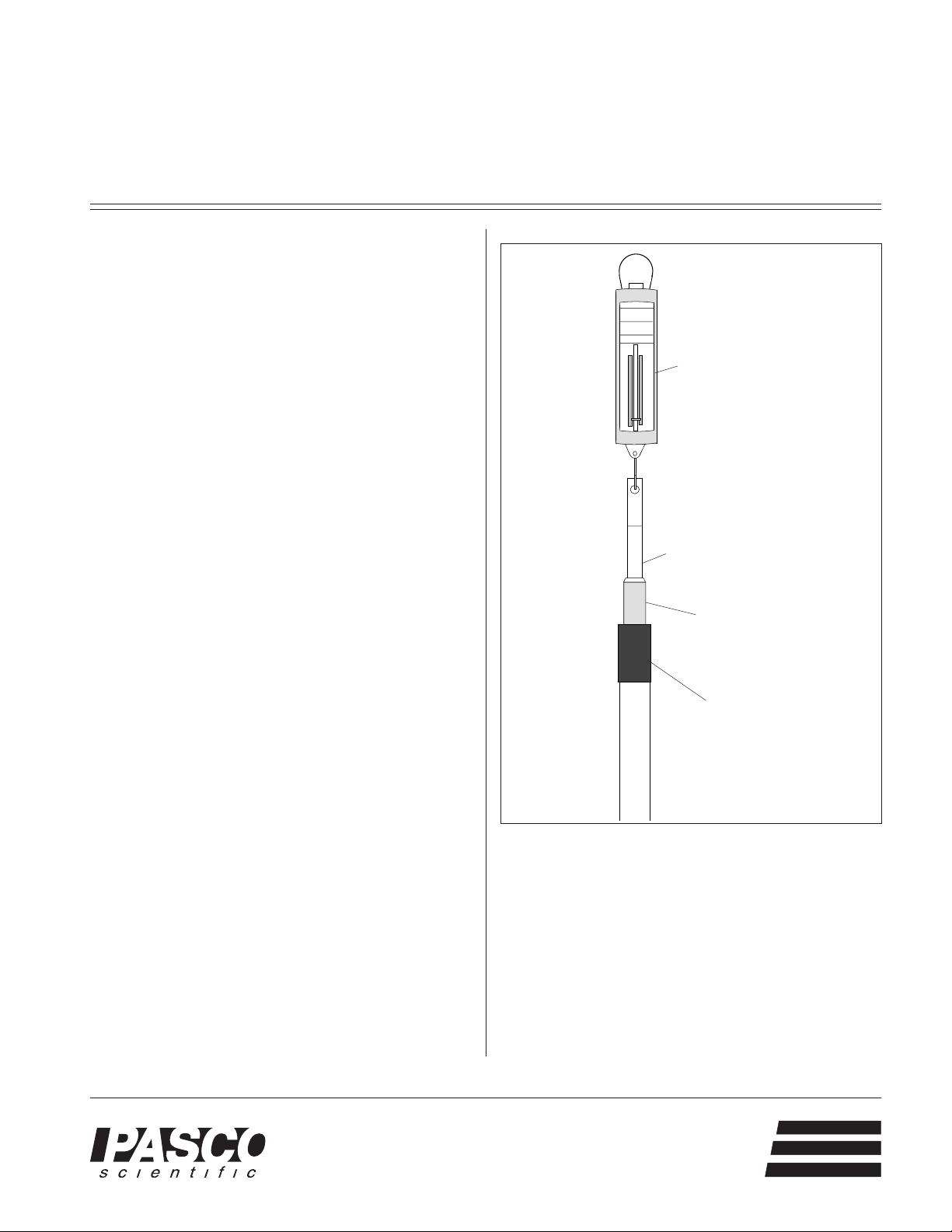
The equipment and setup are shown in Figure 1. Two falling
masses are included with the apparatus. They are seemingly
identical, but one is a magnet, the other is not. A spring
scale is included so you can show that the mass shown on
the scale increases as the magnet falls through the tube, but
not as the unmagnetized mass falls through.
012-03319C
6/90
$.50
Spring scale
To perform the demonstration:
1. Set up the equipment as shown in Figure 1.
2. Hold the unmagnetized mass over the opening in the
tube, then drop it.
3. Now drop the magnet through the tube.
4. You may want to repeat the demonstration, allowing
your students to observe the reading of the spring scale.
Theory
According to Faraday's Law of Induction, a changing
magnetic field induces an electric field. According to
Ampere's Law, a circulating current induces a magnetic
field. So, if a magnetic field changes within a conductor, a
current can be produced which in turn produces a secondary
magnetic field. Lenz's Law states that this secondary
magnetic field always opposes the change in the original
field.
Figure 2a shows a diagram of the magnet falling through the
tube. The N-pole of the falling magnet is facing down.
Three cross sections of the tube, A, B, and C, are shown.
The magnetic field through all three cross sections points
down. In cross section A, the magnetic field decreases as the
magnet falls. Lenz's Law says that the induced field will
therefore point down, reducing the rate at which the total
field decreases. In section B, the field from the falling
magnet is relatively constant. There is therefore no induced
field in cross section B. In cross section C, the field from the
Mounting arm
with velcro pad
Two falling masses
(one of which is a
magnet)
Tube with
velcro pad for
mounting arm
Figure 1 Equipment and Setup
falling magnet increases as the magnet falls. According to
Lenz's Law, the induced field will point up, reducing the rate
at which the total field increases.
An easy way to conceptualize the effect of these fields on the
falling magnet is to imagine the fields as if they are produced
by tiny magnets, as shown in Figure 2b. The direction of the
field of the upper magnet is the same as that of the falling
magnet, so the N-pole of the induced magnet is adjacent to
the S-pole of the falling magnet. The falling magnet is
attracted, which slows its motion. The field of the lower
®
Phone (916) 786-3800 • FAX (916) 786-8905 • email: techsupp@PASCO.com
10101 Foothills Blvd. • Roseville, CA 95747-7100 USA
better
ways to
teach science
Page 2
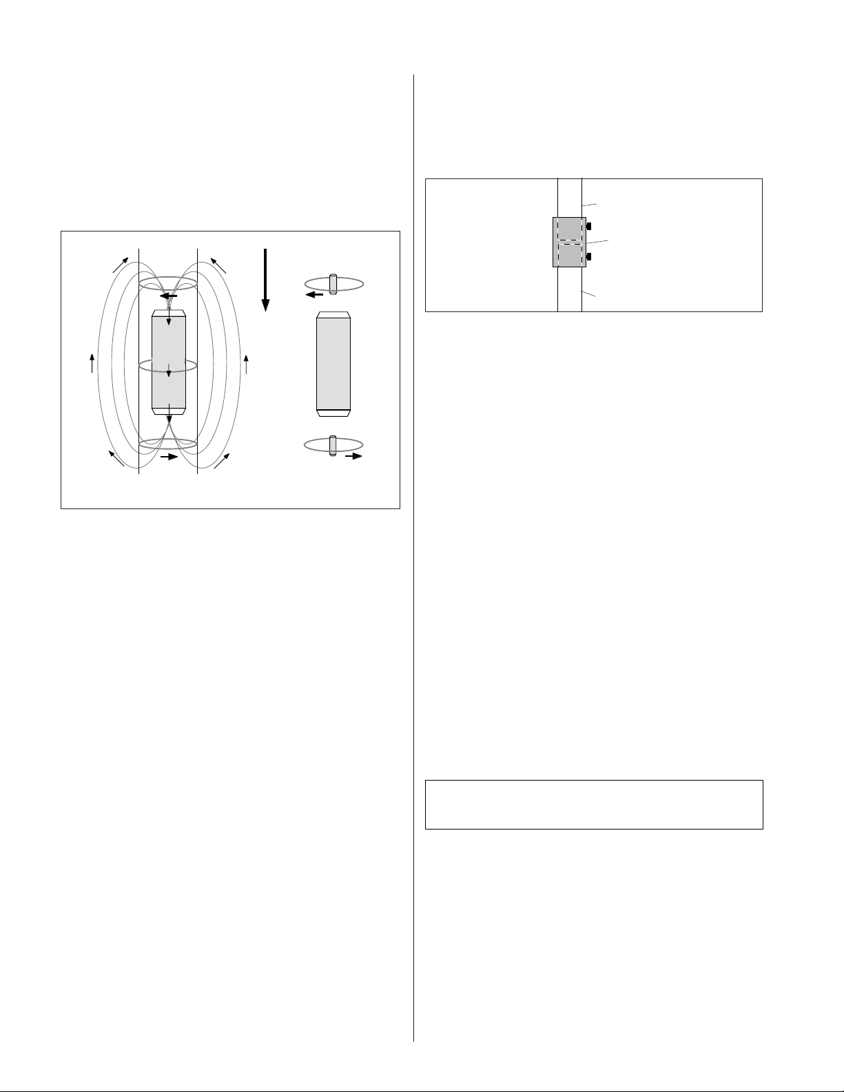
magnet is such that it repels the falling magnet, again,
slowing its motion. Therefore, Lenz's Law predicts that the
motion of the magnet will be slowed due to the induced
fields. Experiment confirms this prediction.
Lenz's Law provides a simple way to determine the directions of induced currents and magnetic fields. However, the
currents and fields can also be determined using more basic
laws of electromagnetics.
Velocity of magnet
A
I
induced
S
N
S
Extending Lenz's Law
You can extend the length of your tube in 1.5 meter increments with the PASCO 1.5 Meter Extension Tube with
Coupler (Model MG-8601). The extension tube and coupler
attach to the Lenz's Law Tube as shown in Figure 3.
Lenz's law tube
Coupler
Extension tube
Figure 3 Attaching the Extension Tube
.
B
N
C
(a)
N
S
I
induced
(b)
Figure 2 Diagram of the Falling Magnet
The direction of the induced currents in the tube can be
determined using Faraday's law of induction, ε = - dØ/dt;
where dØ/dt is the rate of change of the magnetic flux
through a selected cross section of the tube, and ε is the
induced emf around that cross section. The right hand rule
can be used to determine the direction of the current. If the
magnetic flux through the tube is increasing, point your
thumb in the direction opposite the magnetic field (because
of the minus sign). If the magnetic flux through the tube is
decreasing, point your thumb in the direction of the magnetic
field. In each case, your fingers will curl in the direction that
the current flows.
At cross section A, the magnetic field from the magnet is
pointing down, but the field, and therefore the flux, is
decreasing as the magnet descends. The current therefore
flows clockwise (looking down from the top) in that cross
section. At cross section B, the flux due to the field is
constant, because the field near the middle of the magnet is
constant. There are therefore no induced currents in cross
section B. In cross section C, the field points down and the
flux is increasing as the magnet descends. The current
therefore flows counterclockwise.
The circulating currents at cross sections A and C produce
magnetic fields. The magnitude and directions of these fields
can be determined using Ampere's Law ( B dl = µ0I) and a
different right hand rule. Curl the fingers of your right hand
in the direction of current flow. Your thumb will point in the
direction of the magnetic field. Using this rule, you can show
that the predicted directions of the induced fields are the
same as predicted by Lenz's Law.
Limited Warranty
PASCO scientific warrants this product to be free from
defects in materials and workmanship for a period of one
year from the date of shipment to the customer. PASCO
will repair or replace, at its option, any part of the product
which is deemed to be defective in material or workmanship. This warranty does not cover damage to the product
caused by abuse or improper use. Determination of whether
a product failure is the result of a manufacturing defect or
improper use by the customer shall be made solely by
PASCO scientific. Responsibility for the return of equipment for warranty repair belongs to the customer. Equipment must be properly packed to prevent damage and
shipped postage or freight prepaid. (Damage caused by
improper packing of the equipment for return shipment will
not be covered by the warranty.) Shipping costs for
returning the equipment, after repair, will be paid by
PASCO scientific.
Equipment Return
Should this product have to be returned to PASCO scientific,
for whatever reason, notify PASCO scientific by letter or
phone BEFORE returning the product. Upon notification,
the return authorization and shipping instructions will be
promptly issued.
NOTE: NO EQUIPMENT WILL BE ACCEPTED
FOR RETURN WITHOUT AN AUTHORIZATION.
When returning equipment for repair, the units must be
packed properly. Carriers will not accept responsibility for
damage caused by improper packing.
To be certain the unit will not be damaged in shipment,
observe the following rules:
1. The carton must be strong enough for the item shipped.
2. There should be at least two inches of packing material
between any point on the apparatus and the inside of the
carton.
3. Make certain that the packing material can not shift in
the box, or become compressed, thus letting the
instrument come in contact with the edge of the box.
 Loading...