

Page 1
®
Flexible I-beam
ME-9891
Included Equipment Part Number
Flexible I-beam ME-9891
Instruction Manual
012-09977A
Recommended Equipment
Force Sensor
Motion Sensor
2
2
1
PS-2104
PS-2103
or
Rotary Motion Sensor
Large Table Clamp ME-9472
Base and Support Rod ME-9355
45 cm Rod ME-8736
Multi Clamp SE-9442
String (about 1 m) SE-8050
Small hanging mass (about 50 g) SE-8759
(2) Pencils
Adhesive tape (about 20 cm)
1
Equipment recommended for experiment on page 6.
2
Simultaneous use of two PASPORT sensors requires a multi-port PASPORT interface such as Xplorer
GLX (PS-2002) or PowerLink (PS-2001); or two single-por t interfaces such as USB Link (PS-2100).
2
PS-2120
Introduction
The model ME-9891 Flexible I-beam illustrates beam stiffness and deflection. Because it flexes more than a
metal or wooden beam, students can easily observe that its vertical stiffness is greater than its horizontal stiffness. Use the Flexible I-beam to demonstrate how a beam bends under various load and support configurations.
Add sensors to quantitatively explore the concepts of internal moment, second moment of area, and flexural
rigidity.
800-772-8700 www.pasco.com
Page 2
Flexible I -beam Demonstrations
Demonstrations
Ease of Bending
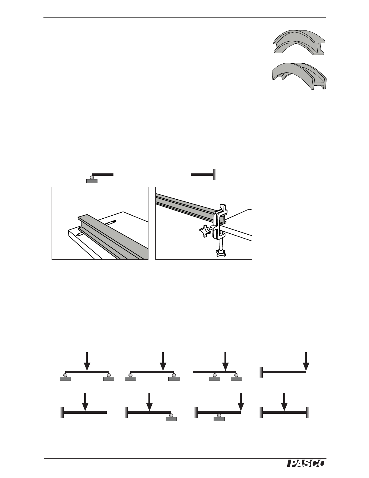
Hold the I-beam in your hands and bend it in the “upright” and “side” directions as
illustrated. In which direction is it easier to bend? For the same effort, in which direction does it bend more?
Elastic Curves
Set up the beam (either upright or on its side) in the support-and-load configurations
diagramed in Figure 3.
The diagrams show two types of support: roller support, which restricts vertical displacement but not rotation; and fixed support, which restricts both displacement and
rotation. Use a pencil for a roller support and a large table clamp (PASCO part
ME-9472) for a fixed support (see Figure 2).
(a) Roller support (b) Fixed support
Figure 2
Figure 1: Exaggerated
illustration of I-beam
bent in upright and side
directions
To apply the load, press down on the beam with your hand or place a mass (about 1
kg) on the beam.
For each configuration, make an exaggerated sketch of the elastic curve showing
where the curvature of the beam is positive (concave upward), negative (concave
downward), and zero (a straight section or an inflection point). Hold a straight edge
against the beam to help determine the direction of curvature. Also mark the point (or
points) of maximum deflection.
Figure 3: Support-and-load configurations for elastic curve demonstration
2
®
Page 3
Model No. ME-9891 Theory
Theory
The deflection of a beam depends on how it is supported, the location and magnitude
of the load, the beam’s elastic modulus (E), and its second moment of area (I).
The vertical deflection of a beam (y) can be found using the formula
(eq. 1)
d2y
--------
dx
M
------=
2
EI
where M is the internal bending moment at horizontal position x. The product EI is
the beam’s flexural rigidity.
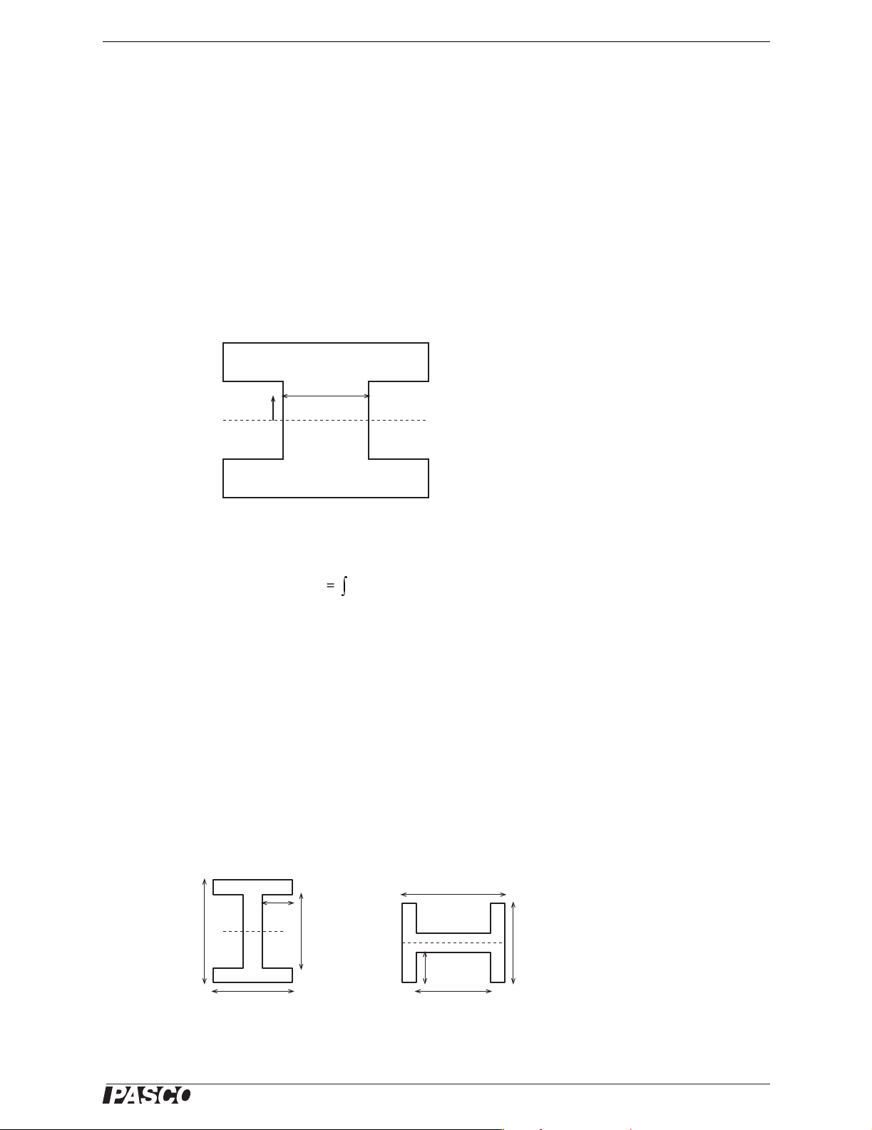
Second Moment of Area
b(y)
y
Figure 4
The second moment of area for a beam of constant cross section is
(eq. 2)
Iy2by()yd
=
∫
neutral axis
where b(y) is the width of the section at a distance y from the neutral axis (Figure 4).
For the upright I-beam in Figure 5a, the second moment of area is
3
(eq. 3)
WH
I
----------------------------= upright
12
3
wh
–
For the same I-beam turned on its side (Figure 5b), the second moment of area is
(eq. 4)
3
hW w–()
Hh–()W
----------------------------------------------------------=side
I
+
12
3
Note that these formulas for I are for calculating vertical deflection.
H
w/2
H
h
W
w/2
W
(a) upright
Figure 5
h
(b) sideways
®
3
Page 4

Flexible I -beam Theory
Moment Functions
To predict the deflection of a beam, it is first necessary to express the internal moment
M as a function of x along the entire length of the beam. In some cases, the beam must
be divided into regions with a different function for each region.
A detailed description of this analysis can be found in most structural analysis text
books. Here, we will simply give the solutions for two examples relevant to the experiment below.
FL/4
y
M
x
F
L
L/2
(a)
y
x
L
M
x
L
Figure 6
-FL
(b)
F
L
x
The beam in Figure 6a is supported on two rollers with the load applied in the center.
Each support applies an upward force equal to F/2. In the left half of the beam, the
internal moment is for . The internal moment in the right
half is .
M
2
M
Fx 2⁄=0xL2⁄≤≤
1
Fx L–()2⁄–=
The cantilevered beam in Figure 6b is supported by a single fixed support. To counter
the load, the support applies an upward force equal to F, and a counter-clockwise
moment of Fx. The internal moment (for any value of x along the length of the beam)
is M = F(x - L).
4
®
Page 5

Model No. ME-9891 Theory
Deflection Functions
The deflection of a beam under load can be found by combining Equation 1 with the
moment function (or functions) and integrating twice to solve for y. Below are two
examples of this method used to derive the deflection functions of the beams in Figure 6.
Example 2: Cantilevered BeamExample 1: Three-point Bending
For the left half of the beam in Figure 6a,
= Fx/2. Combine that function with
M
1
Equation 1:
2
EI
d
y
------
F
--------
dx
x
---=0xL2⁄≤≤
2
2
Integrate once:
EI
------
F
dy
------
dx
2
x
+=
----- C
4
1
From symmetry, we know that the slope of
the beam at its center is zero: dy/dx =0 at
x = L/2; therefore C
=-L2/16.
1
Integrate again:
3
EI
------
F
y
x
-----12
2
x
L
+–=
--------- C
16
2
Because the roller support restricts displacement, y =0 at x = 0; therefore C
F
------------
y
48EI
3
4x
3L2x–()=0xL2⁄≤≤
=0, and
2
The maximum displacement occurs at
x = L/2:
To solve the equation for the cantilevered
beam in Figure 6b, combine M = F(x - L)
with Equation 1:
2
EI
d
y
--------
------
F
dx
xL–=
2
Integrate once:
EI
------
F
dy
------
dx
2
x
----- Lx– C
+=
2
1
Because the fixed support restricts rotation,
we know that the slope at the support is zero:
dy/dx =0 at x = 0; therefore C
= 0.
1
Integrate again:
3
6
2
Lx
+=
---------– C
2
2
EI
------
F
x
-----
y
Because the fixed support restricts displacement, we know that y =0 at x = 0; therefore
C
=0, and
2
F
y
6EI
x
3
---------
–()=
3Lx
2
The maximum displacement occurs at x = L:
3
y
max
FL
------------–=
48EI
The right side of the beam can be solved for
using Equation 1 and M
=-F (x - L)/2; how-
2
ever this is not necessary if we are interested
only in the maximum displacement at the
center of the beam.
®
y
max
FL
----------–=
3EI
3
5
Page 6
Flexible I -beam Experiment: Three-point Bending
Experiment: Three-point Bending
Equipment
See Equipment Table on page 1.
Introduction
In this experiment, the I-beam will be supported on two rollers (Figure 7) with a downward load force applied to the center. You will
use sensors to measure maximum displacement as a function of
applied force. You will repeat the measurement with the beam
turned on its side.
The upright beam is more rigid than the sideways beam; therefore,
the sideways beam will deflect more.
Before proceeding, predict how much more the sideways beam
will deflect (compared to the upright beam) for a given force.
Record your prediction and explain how you made it.
58 cm
Tape
Note: The following instructions assume that you are familiar with setting up
PASPORT sensors and analyzing data in DataStudio software or on the
Xplorer GLX. For more information, see the instructions that came with your
sensors and interface, or press F1 to open DataStudio’s on-line help.
Set-up
1. Place two pencils on your bench top about 58 cm apart (Figure 7).
2. Tape down the pencils to prevent them from moving.
3. Place the I-beam in the upright orientation on the pencils.
4. Set up one of the following sensor options (motion sensor or rotary motion sen-
sor) to measure vertical deflection at the center of the beam.
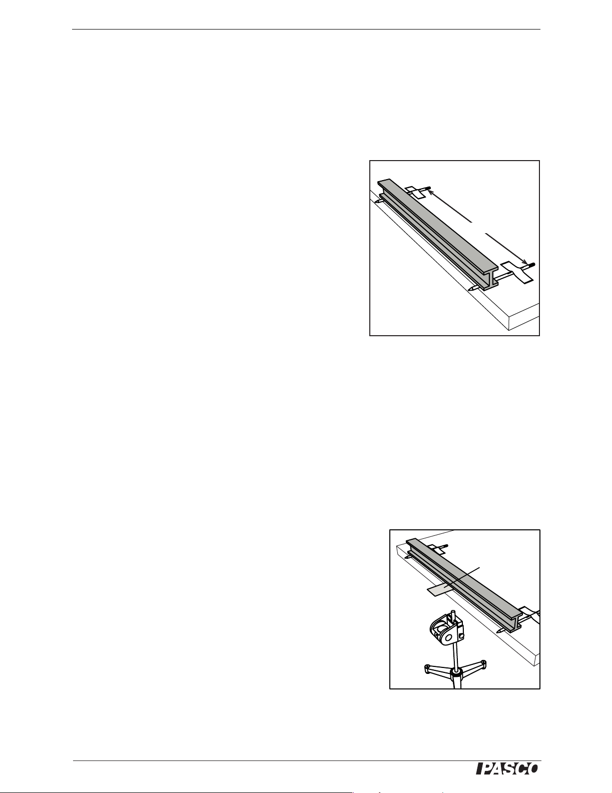
Motion Sensor option:
a. Tape a card to the bottom of the I-beam in the center as shown
in Figure 8; this card will overhand the edge of the bench and
reflect the motion sensor’s ultrasonic pulses.
b. Mount the motion sensor on a rod stand on the floor under the
card. Aim the sensor at the bottom of the card. The sensor
should be at least 15 cm from the card.
Figure 7: Experiment Set-up
Card taped to
beam
c. Set the switch on the motion sensor the near-range setting.
d. Connect the motion sensor to your PASPORT interface.
Motion
Sensor
e. Record some sample data and ensure that the sensor “sees” the
bottom of the card and not the bottom of the lab bench. When
you push down on the I-beam, the measured position should
Figure 8: Motion Sensor
change by a few millimeters.
6
®
Page 7
Model No. ME-9891 Experiment: Three-point Bending
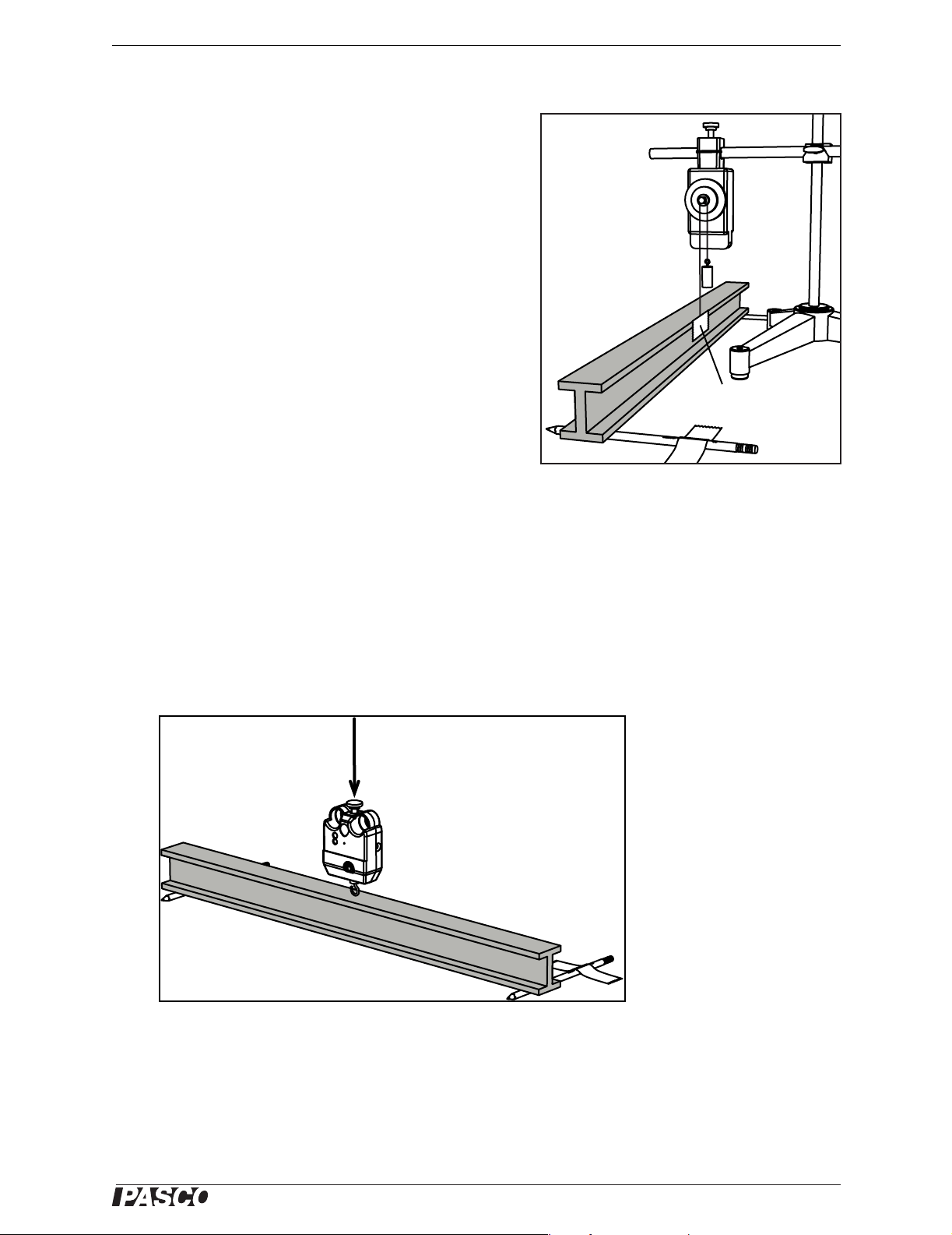
Rotary Motion Sensor option:
a. Install the three-step pulley (included with the sensor)
on the rotary motion sensor.
b. Mount the rotary motion sensor above the I-beam as
(shown in Figure 9) using a stand, clamp, and rods.
c. Tape a piece of string to the center of the I-beam. Run
the string over the smallest step of the three-step
pulley. Hang a small mass (about 50 g) from the end
string.
d. Connect the rotary motion sensor to your PASPORT
interface.
e. In the Setup window of DataStudio (if you are using
a computer) or in the Sensors screen of the Xplorer
GLX (if you are using it in standalone mode), turn on
the Linear Position measurement and set the Linear
Scale setting to “Small Pulley (Groove)”.
5. Connect a force sensor to your PASPORT interface.
Procedure
1. Start data recording.
2. Hold the force sensor in your hand and push straight down on the center of the
I-beam (Figure 10). Gradually increase the applied force until the I-beam has
deflected a few millimeters.
Rotary Motion
Sensor
~50 g mass
Ta p e s tr i ng
to beam
Figure 9: Rotary Motion Sensor
3. Stop data recording.
Push
Force Sensor
Figure 10: Push down with force sensor
4. Turn the I-beam on its side, adjust the deflection-measuring sensor, and repeat
the procedure.
®
7
Page 8

Flexible I -beam Experiment: Three-point Bending
Analysis
1. For the data taken with the beam in the upright orientation, make a graph of y
(the measured deflection in the center of the beam) versus F (the force applied by
the force sensor).
2. Apply a linear fit to the data. The relationship between y
3
L
y
max
Therefore, the slope of the best-fit line is .
–=
------------
F
48 EI
3
48EI()⁄–
L
and F is given by
max
3. Measure L, the distance between the supports.
4. Use the slope of the best-fit line and L to find EI, the beam’s flexural rigidity.
5. Repeat the analysis for the beam in the side orientation.
Questions
1. In which orientation did the beam have greater flexural rigidity? How much
greater was it?
2. Was the prediction that you made at the beginning of this experiment accurate?
max
Further Study
Repeat the experiment with a cantilevered beam (Figure 2b). Does the maximum
deflection for a given force change? Does the flexural rigidity change?
8
®
Page 9

Model No. ME-9891 Typical Results
Typical Results
Typical data for the three-point bending experiment are shown below:
Upright Side
Motion Sensor:
Rotary Motion Sensor
®
9
Page 10

Flexible I -beam Specifications
Specifications
Length 61 cm (24 inches)
Height 5 cm (2 inches)
Width 4 cm (1.5 inches)
Technical Support
For assistance with any PASCO product, contact PASCO at:
Address: PASCO scientific
10101 Foothills Blvd.
Roseville, CA 95747-7100
Phone: 916-786-3800 (worldwide)
800-772-8700 (U.S.)
Fax: (916) 786-7565
Web: www.pasco.com
Email: support@pasco.com
Limited Warranty
For a description of the product warranty, see the PASCO catalog.
Copyright
The PASCO scientific 012-09977A
non-profit educational institutions for reproduction of any part of this manual, providing the reproductions are used only in their laboratories and classrooms, and are not sold for profit. Reproduction under any other circumstances, without the written consent of PA SCO
scientific, is prohibited.
Trademarks
PASCO, PASCO scientific, DataStudio, PASPORT, Xplorer, and Xplorer GLX are trademarks or registered trademarks of PASCO scientific, in the United States and/or in other countries. All other brands, products, or service names are or may be trademarks or service marks of, and are used to identify, products or services of, their respective owners. For more information visit
www.pasco.com/legal.
Flexible
I-beam
Instruction Manual
is copyrighted with all rights reserved. Permission is granted to
10
®
 Loading...