

Page 1

®
PASCO Mechanics
Statics System
ME-9502
Instruction Manual
012-12876B
*012-12876*
Page 2

®
The cover page shows a a Friction Block on the Statics System Inclined Plane with a PASCO Mass Hanger from
the ME-8979 Mass and Hanger Set suspended by a thread over a Small Pulley. Most of the components of the
Statics System are held magnetically to the included workboard. This manual contains fifteen copy-ready experiments about the fundamentals of statics.
ii
Page 3

®
Table of Contents
Introduction . . . . . . . . . . . . . . . . . . . . . . . . . . . . . . . . . . . . . . . . . . . . . . . . . . . . . . . . . . . 1
Equipment . . . . . . . . . . . . . . . . . . . . . . . . . . . . . . . . . . . . . . . . . . . . . . . . . . . . . . . . . . . .1
Recommended Equipment . . . . . . . . . . . . . . . . . . . . . . . . . . . . . . . . . . . . . . . . . . . . . . . 3
Spares Package. . . . . . . . . . . . . . . . . . . . . . . . . . . . . . . . . . . . . . . . . . . . . . . . . . . . . . . . 4
Components Package . . . . . . . . . . . . . . . . . . . . . . . . . . . . . . . . . . . . . . . . . . . . . . . . . . . 5
About the Manual. . . . . . . . . . . . . . . . . . . . . . . . . . . . . . . . . . . . . . . . . . . . . . . . . . . . . . 10
EXPERIMENTS
1. Hooke’s Law - Measuring Forces . . . . . . . . . . . . . . . . . . . . . . . . . . . . . . . . . . . . . . . 11
2. Adding Forces - Resultants and Equilibriants . . . . . . . . . . . . . . . . . . . . . . . . . . . . . . 13
3. Resolving Forces - Components . . . . . . . . . . . . . . . . . . . . . . . . . . . . . . . . . . . . . . . . 17
4. Torque - Parallel Forces . . . . . . . . . . . . . . . . . . . . . . . . . . . . . . . . . . . . . . . . . . . . . . 21
5A. Center of Mass . . . . . . . . . . . . . . . . . . . . . . . . . . . . . . . . . . . . . . . . . . . . . . . . . . . . 25
5B. Equilibrium of Physical Bodies . . . . . . . . . . . . . . . . . . . . . . . . . . . . . . . . . . . . . . . . 29
6. Torque - Non-Parallel Forces. . . . . . . . . . . . . . . . . . . . . . . . . . . . . . . . . . . . . . . . . . . 33
7. The Inclined Plane . . . . . . . . . . . . . . . . . . . . . . . . . . . . . . . . . . . . . . . . . . . . . . . . . . . 37
8. Sliding Friction and Static Friction . . . . . . . . . . . . . . . . . . . . . . . . . . . . . . . . . . . . . . . 41
9. Simple Harmonic Motion - Mass on a Spring. . . . . . . . . . . . . . . . . . . . . . . . . . . . . . . 47
10. Simple Harmonic Motion - The Simple Pendulum . . . . . . . . . . . . . . . . . . . . . . . . . . 53
11A: Simple Harmonic Motion - Physical Pendulum . . . . . . . . . . . . . . . . . . . . . . . . . . . 57
11B: Minimum Period for a Physical Pendulum. . . . . . . . . . . . . . . . . . . . . . . . . . . . . . . 63
11C: Simple Harmonic Motion - Beam on a Spring . . . . . . . . . . . . . . . . . . . . . . . . . . . . 67
12. Simple Machines - The Lever . . . . . . . . . . . . . . . . . . . . . . . . . . . . . . . . . . . . . . . . . 73
13. Simple Machines - The Inclined Plane. . . . . . . . . . . . . . . . . . . . . . . . . . . . . . . . . . . 77
14. Simple Machines - The Pulley . . . . . . . . . . . . . . . . . . . . . . . . . . . . . . . . . . . . . . . . . 81
15. Forces on a Boom . . . . . . . . . . . . . . . . . . . . . . . . . . . . . . . . . . . . . . . . . . . . . . . . . . 83
Technical Support, Warranty, and Copyright. . . . . . . . . . . . . . . . . . . . . . . . . . . . . . . . . 85
iii
Page 4

®
Statics System
iv 012-12876B
Page 5
Statics System
®
If F 0 then a = 0=
a
F
net
m
----------
=
Statics Board
ME-9502
Introduction
The study of mechanics often begins with Newton’s Laws of Motion. The first law describes the conditions for an
object to maintain its state of motion. If the net force on an object is zero, the acceleration of the object is zero.
The second law describes what happens if the net force on an object is not zero. The acceleration is directly proportional to net force, in the same direction as the net force, and inversely proportional to mass, or
Much of what is studied in an introductory course deals with the ways that forces interact with physical bodies.
The PASCO Statics System is designed to help you investigate the nature of forces for the special case in which
there is no acceleration. In other words, the vector sum of all the forces acting on the body is zero.
One reason to study the case of no acceleration is because it is easier to measure non-accelerating systems than it
is to measure accelerating systems. A great deal can be learned about the vector nature of forces by studying the
many ways in which forces can be applied to an object without causing acceleration.The second reason is that in
our everyday experience, non-accelerated systems are the rule, not the exception.
Equipment
The ME-9502 Statics System consists of the Statics Board, Spares Package, Components Package, and Mass and
Hanger Set.
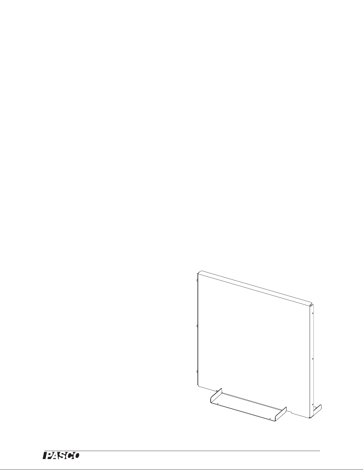
ME-9503 Statics Board
The Statics Board is a ferrous metal plate approximately
45 by 45 centimeters (18 by 18 inches) with a writable
white board finish on both sides.)
The board has rubber bumpers on its base. White board
pens (or “dry erase” pens) can be used to write and draw
directly on the board. The pens are available from stationery stores and the ink can be erased with a cloth or a
white board eraser.
The Mounted Scale Assembly, Large and Small Pulley
Assemblies, Balance Arm Assembly , Force Wheel Assembly, Torque Wheel Assembly, Inclined Plane Assembly,
and Utility Mount Assembly all attach magnetically to t he
board. Components can be stored on the rear side of the
board when not in use. Except for the Inclined Plane
Assembly, all the components that can mount on the board
have a rubber ring on the base that protects the board and
the component. The round magnetic base is 6.5 centimeters (cm) in diameter.
1
Page 6
Statics System Equipment
®
No
No
Yes
Yes
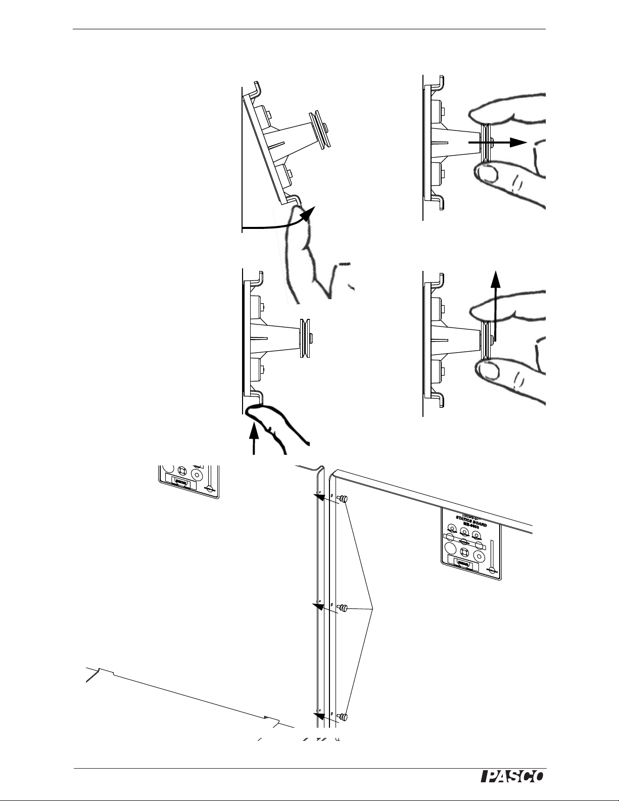
Moving Components on the Board
Rear view of Statics Boards
Connector
screws
Use the Connector
screws to join two
Statics Boards together.
Important
When moving or removing any of
the magnetically mounted components from the board, handle the
component by the magnetic base
rather than by the component itself.
This will reduce the strain on the
component.
A second board (available separately) can be attached to the first
board with the three included connector screws. To join the boards,
remove the connector screws from
the threaded holes on the side of
the first board. Put the edge of the
second board next to the first
board. Align the holes and join the
two boards with the connector
screws
.
2
012-12876B
Page 7

®
Model No. ME-9502 Recommended Equipment*
ME-8979 Mass and Hanger Set
PS-2201 5 N Load Cell
Amplifier Model
Load Cell Amplifier (PASPORT) PS-2198
Dual Load Cell Amplifier PS-2205
Load Cell Amplifier (ScienceWorkshop) CI-6464
ME-9504 Spares Package
Item Qty Item Qty
String Tie Assembly 3 Thumbscrew 6-32 by 5/8” (for Cord Clip) 2
Torque Indicator Assembly 6 Thumbscrew 4-40 by 1/2” (for balance arm protractor) 2
Nylon Thread, spool 1 Thumbscrew 6-32 by 1/4” (for balance arm pivot) 1
Cord Tensioning Clip 2 Washer 0.285” OD (for balance arm protractor) 2
Angle Indicator Arm 2 Plumb bob, brass (for inclined plane) 1
ME-9505 Components Package
Item Qty Item Qty
Large Pulley Assembly 1 Utility Mount Assembly 1
Small Pulley Assembly 2 Mass Cart Assembly 1
Mounted Scale Assembly 1 Torque Wheel Assembly 1
Balance Arm Assembly 1 Inclined Plane Assembly 1
Force Wheel Assembly 1 Friction Block Assembly 1
Double Pulley Assembly 1 Asymmetrical Plate 1
ME-8979 Mass and Hanger Set
Components from the ME-8979 P ASCO Mass and Hanger Set are used
in most of the statics experiments. The set includes four mass hangers,
a storage box, and twenty-seven masses ranging from 0.5 g to 100 g
made from brass, aluminum, or polycarbonate plastic.
Recommended Equipment*
Load Cell and Load Cell Amplifier
A PS-2201 5 N Load Cell can be used to measure force. When it is connected through an amplifier to a PASCO interface or to a PASCO
hand-held data logger, the force data from the Load Cell can be
recorded, displayed, and analyzed.
.
*See the PASCO catalog or Web site at www.pasco.com for information about PASCO load cells, load cell
amplifiers, interfaces, hand-held data loggers, and data acquisition software.
012-12876B 3
Page 8
Statics System Spares Package (ME-9504)
®
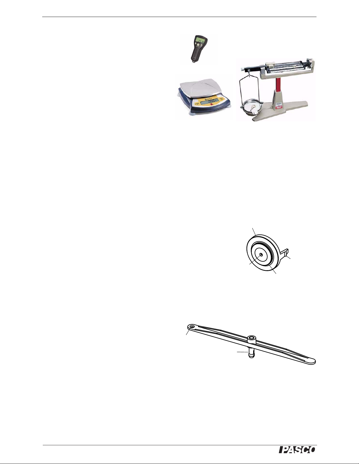
Mass Balances
Stop Watch
Inner part
(force disk)
Outer part
Tab
Put
threads
through
this hole.
String Tie Assembly
T orque Indicator Assembly
Tie a
thread to
this hole.
Snap connects
to Torque Wheel
Stopwatch (ME-1234)
The PASCO Stopwatch has a liquid crystal display (LCD) with two display modes. Its precision
is 0.01 seconds up to 3599.99 seconds, and 1 second up to 359999 seconds. Its memory holds up to
nine event times.
Mass Balance
Use a mass balance such as the OHAUS Scout
Pro Balance 2000 g (SE-8757A) or the OHAUS
Cent-O-Gram Balance (SE-8725).
Mounted Scale Assembly (ME-9824A)
The Mounted Scale Assembly (included in the ME-9505 Components Package) is also available separately as a
replacement or as an extra spring scale for experiments where measuring more than one force is required.
Spares Package (ME-9504)
The Spares Package contains some items which are used with assemblies from the Components Package. For
example, the String Tie Assembly snaps into the center of the Force Wheel Assembly and the Torque Indicator
Assembly snaps into the Torque Wheel Assembly. The Cord Tensioning Clip is used on the Utility Mount Assembly. Other items such as the Angle Indicator Arms, thumbscrews, washers, and brass weight are replacement parts.
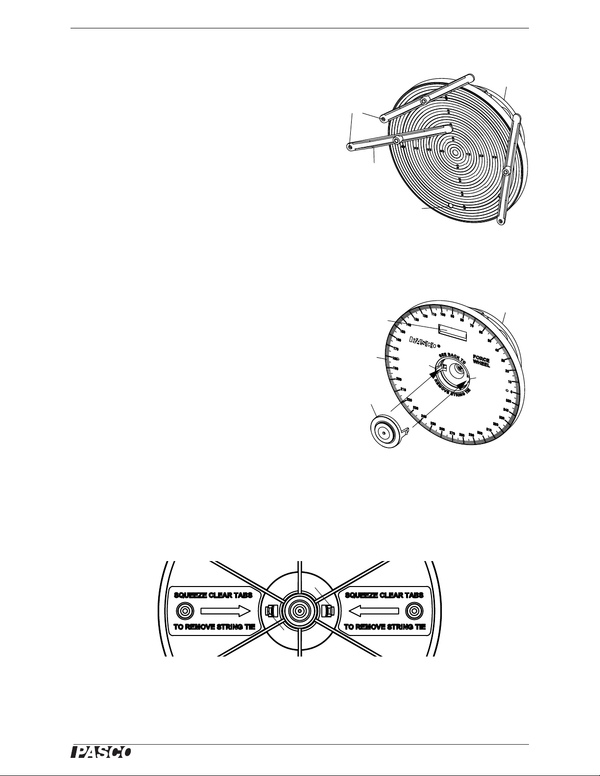
String Tie Assembly.
When the String Tie Assembly is snapped into the center of the Force
Wheel Assembly, you can use the apparatus to study force vectors. The
String Tie Assembly has two parts: a clear plastic inner part (the “force
disk”) that is free to move around in the center of the outer part, which
has a center hole and two tabs that snap into the Force Wheel Assembly.
(The two parts are not meant to be separated.)
Initial Setup
Get three threads that are 38 cm (15”) long. Put the threads through the
hole in the inner part of the String Tie Assembly. Tie the ends of the
threads together (for example, with an overhand knot) so that they cannot be pulled back through the inner part.
Torque Indicator Assembly
Note that the Torque Indicator Assembly has a
snap that can be connected to the Torque Wheel
Assembly . The other three assemblies are
spares.
Initial Setup
Tie a 30 cm (12”) thread to each of three Torque Indicator Assemblies.
4
012-12876B
Page 9

®
Model No. ME-9502 Components Package (ME-9505)
Spring
Indicator
disk
Scale
Base
Bottom
hook
Thumbnut
Top hook
Tab
Tube
Mounted Scale Assembly
Zero
mark
Small Pulley (2) Large Pulley Double Pulley Block
Mass Cart Friction Block
Felt
Hook
Rod for
stacking
masses
Wood
Components Package (ME-9505)
Mounted Scale Assembly
The mounted scale has four strong magnets in its base. The tube is marked in
newtons (N), ounces (oz.) and millimeters (mm). The thumbnut allows the top
hook to be raised or lowered in order to align the red indicator disk with the
zero mark on the tube.
T o zero the scale, mount the scale on the statics board. Leave the bottom hook
empty. Unscrew the thumbnut a few turns. Rotate the top hook clockwise
(left-to-right) to lower the indicator disk and counter-clockwise (right-to-left)
to raise the indicator disk. When the disk is aligned with the zero mark on the
tube label, tighten the thumbnut to hold the top hook in place.
To move the scale on the statics board, hold the scale by the tabs on the base
and push or pull the scale to the desired location. To remove the scale from the
statics board, lift one or both of the tabs on either side of the base away from
the board.
Large and Small Pulleys and Double Pulley Block
The Statics System comes with two Small Pulleys and one Large Pulley
mounted on magnetic bases. It also includes a Double Pulley Block (that does
not have a magnetic base). The Double Pulley Block is designed for
block-and-tackle experiments. A support thread can be tied to either end of the
Double Pulley Block.
All the pulleys have low friction ball bearings. The smaller pulleys are 2.41
cm (0.850”) outside diameter (OD) and 1.65 cm (0.650”) inside diameter (ID).
The larger pulleys are 2.79 cm (1.10”) OD and 2.28 cm (0.90”) ID.
Please use the tabs on the base of the components when moving them around or removing them from the statics
board.
Mass Cart and Friction Block
The Mass Cart and Friction Block are
designed to be used with the Inclined Plane
Assembly. The Mass Cart has low friction ball
bearings in each wheel and a metal rod in the
center for stacking extra masses. A thread can
be attached at either end.
The Friction Block is made of beech wood. It
has an “eye” hook at one end and is covered
with felt on the bottom and one side. Its dimensions are 2.54 cm by 5.08 cm by 6.35 cm (1.0” by 2.0” by 2.5”).
012-12876B 5
Page 10
Statics System Components Package (ME-9505)
®
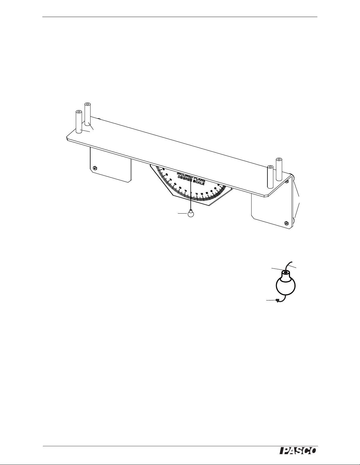
Inclined Plane Assembly
End stops
Plumb bob
Brass Weight
Put thread
through
the hole.
Tie a
knot.
Thread
Inclined Plane Assembly
The Inclined Plane Assembly has four strong magnets on its back side that hold it in position on the Statics Board.
CAUTION: The magnets on the Inclined Plane Assembly are not covered with protective material.
Be careful to firmly hold the inclined plane when placing it on the board so that the magnets are
not damaged by “snapping” against the board.
The inclined plane has end stops at each end of the plane and a degree scale with a brass plumb bob for determining the angle of the incline.
Replacing the Plumb Bob
The ME-9504 Spares package includes a spare plumb bob (brass weight). To
replace the plumb bob, use a Phillips head (“crosshead”) screwdriver to loosen
the screw on the back of the degree scale. Remove the piece of thread and get a
new piece approximately 10 cm (4”) long. Put one end of the thread through the
hole in the brass weight and tie a double knot in that end of the thread so it will
not slip back through the hole. Put the other end of the thread through the small
hole near the top of the degree scale. Adjust the length of the thread so the plumb
bob can swing freely and then wind the end of the thread around the screw on the
back. Tighten the screw to hold the thread in place.
Magnets
6
012-12876B
Page 11
®
Model No. ME-9502 Components Package (ME-9505)
Torque Wheel Assembly
Torque Indicator Assembly
Tie a thread
to the hole.
Hole
Base
Torque
Indicator
Force Wheel Assembly
String Tie Assembly
Notch
String
Tie
Bubble
level
Base
Degree
scale
Notch
Tab
Tab
Torque Wheel Assembly and Torque Indicator Assembly
The Torque Wheel Assembly has a 5 cm radius disk with a
label that has concentric circles 2 mm apart. The disk rotates
freely on a ball bearing and has five holes for attaching a
T orque Indicator Assembly. The Torque Indicator snaps into
the hole and rotates freely. Tie a 30 cm (12”) thread to the hole
in the end of each indicator.
To remove a Torque Indicator, firmly grasp the indicator at the
pivot in the middle and pull outwards while pushing on the end
of the snap from the other side of the disk.
Force Wheel Assembly and String Tie Assembly
The Force Wheel Assembly has a 5 cm radius disk with a 360°
label and a bubble level for leveling the Force Wheel. Unlike
the Torque Wheel, the Force Wheel does not rotate freely but
the disk can be turned in order to level the wheel. Once leveled,
the wheel will stay in position until moved again.
REMINDER: Be sure to put tie three threads through the hole
in the center of the String Tie before putting the String Tie into
the Force Wheel.
The String Tie Assembly snaps into the hole in the center of the
Force Wheel Assembly. Align the tabs on the String Tie with
the notches inside the hole at the center of the Force Wheel.
Push the String Tie firmly into the Force Wheel until both tabs
“snap” into place. Note that the surface of the outer part of the
String Tie will be very slightly below the surface of the Force
Wheel, but the inner part of the String Tie will be flush with the
Force Wheel.
Removing the String Tie Assembly
If you need to remove the String Tie (in order to replace the threads, for example), remove the Force Wheel from
the Statics Board. On the underside of the disk are instructions about removing the String Tie.
Remove String Tie
012-12876B 7
Page 12
Statics System Components Package (ME-9505)
®
String Tie
Base
Force Wheel
Remove String Tie
Beam
Pivot
base
Bubble
level
Protractor
Tie a
thread to
the hole.
Angle Indicator
Thumbscrew
Thumbscrew
Washer
Balance Arm Assembly
Indicator
line
This tick
mark is at
50 mm.
This tick
mark is at
60 mm.
Note: The Angle Indicator is
not shown in this example.
Reading the Scale
(Imagine that the Force Wheel disk is transparent so that you can see the String Tie.) Hold the Force Wheel as
shown and push the clear plastic tabs inward with your forefingers until the String Tie pops out of the Force
Wheel.
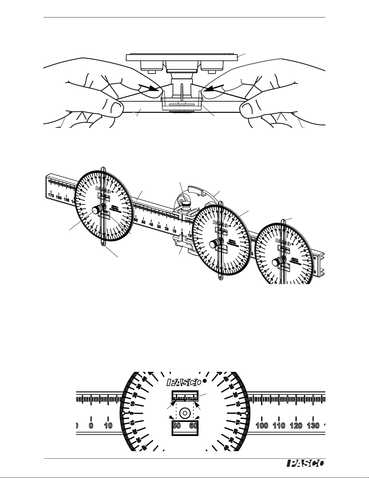
Balance Arm Assembly
The Balance Arm Assembly consists of a Beam, a Pivot, and three Protractors that can be mounted on the beam.
Each protractor has a transparent Angle Indicator. The pivot has a bubble level for leveling the beam.
Adjust the beam by loosening the thumbscrew on the top of the pivot and sliding the beam one way or the other.
Move the protractors by loosening the thumbscrew at the center of the protractor and sliding the protractor along
the beam. Note that not all experiments need three protractors.
Reading the Scale
Read the position of the protractor relative to the midpoint through the two rectangular windows on the protractor.
The bottom window shows the position to the nearest centimeter, and the top window shows the position to the
millimeter. The top window has a small indicator line on its bottom edge. The bottom window in the example
shows the position as between 50 mm and 60 mm and the top window shows it at 55 mm.
8
012-12876B
Page 13
®
Model No. ME-9502 Components Package (ME-9505)
Utility Mount
Base
Rod for
Asymmetrical
Plate
Thumbscrew and
post for Load Cell
Attach a Cord
Clip here.
Attaching a Load Ce ll
Thumbscrew
Post
Cord Clip
Thread
Load Cell
Figure A: Hold the
cord clip so the two
parts separate
Figure B: Loop the
thread back through
the cord clip
Figure C: The thread
goes around the
screw hole
Figure D: The cord clip is ready to
be attached to a Utility Mount or a
Load Cell
Thumbscrew
hole
Peg
Threaded
post
Peg
Attaching a Cord Clip
Small
diameter
post
Base
Align the peg of the Cord
Clip with the hole in the
small diameter post.
Use the 5/8” thumbscrew
to attach the Cord Clip to
the threaded post.
Utility Mount Assembly
The Utility Mount has several functions. It can support a PS-2201 5 N
Load Cell, it has a rod from which you can hang the Asymmetrical
Plate, and the included Cord Tensioning Clip allows you to connect a
thread to the mount. The thumbscrew for the Load Cell is “captured”
by a rubber O-ring so that it will not fall out of the mount.
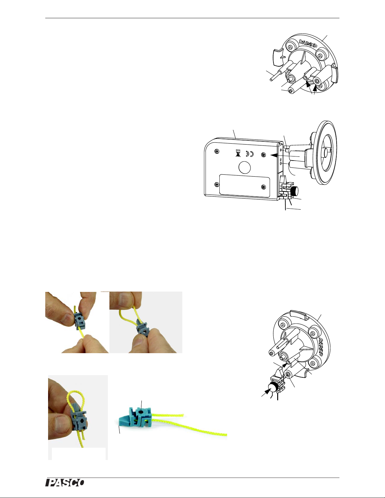
Attaching a Load Cell
You can use a 5N Load Cell (available separately) with
the Statics System to measure a force in much the same
way that the Mounted Scale can be used to measure a
force. (In fact, after the Load Cell is calibrated, it could be
used to calibrate the Mounted Scale.) First, loop a thread
through a Cord Clip (see below) and then attach the clip
to the “LOAD” position that is imprinted on the side of
the Load Cell. Next, attach the Load Cell’s “FIXED” end
to the thumbscrew and post on the Utility Mount.
Using a Cord Clip
The Cord Clip connects to the Utility Mount so that to a
thread and be attached to the Mount itself. Use the Clip
to attach a thread to a Load Cell (see above) that is mounted on the Utility Mount.
It is best to attach the thread through the clip before the clip is installed on the mount or on a Load Cell. The Cord
Clip has two parts but it does not come apart. Start by holding the top part of the clip so the two parts are separate
as shown in Figure A, leaving an opening through which the thread can be threaded. Insert the thread into the flat
end (not the pointed end) of the clip. Loop the thread back through the clip as shown in Figure B and Figure C.
Attach the Cord Clip to the Load Cell or the Utility Mount using the thumbscrew to tighten the clip shut.
012-12876B 9
Page 14
Statics System About the Manual
®
Rod
Asymmetrical Plate
Base
Suspend the Asymmetrical Plate
Utility
Mount
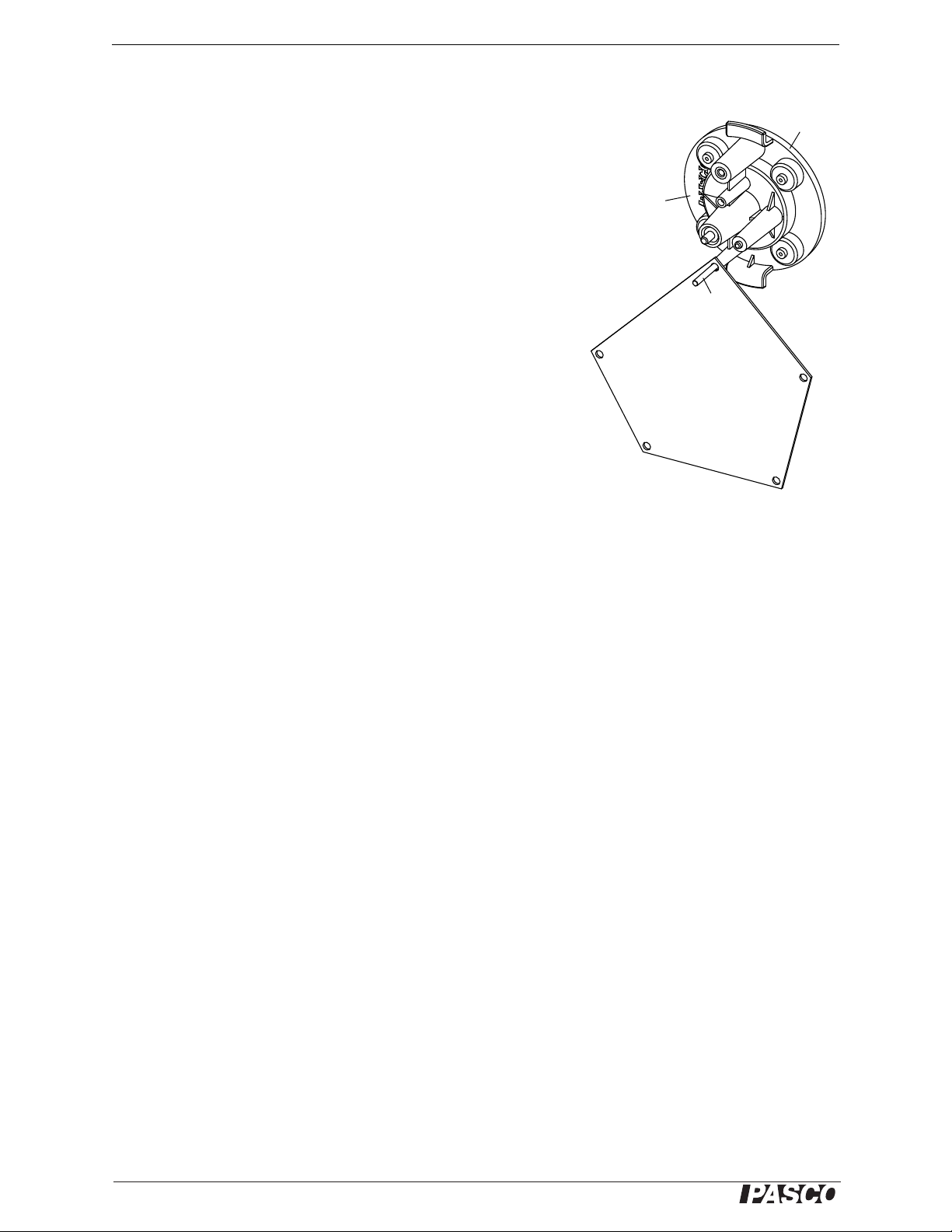
Asymmetrical Plate
The Asymmetrical Plate is a five-sided polygon with a small hole at
each corner. The Utility Mount has a slender metal rod designed to support the Asymmetrical Plate so that the plate can swing on the rod until
it reaches equilibrium.
About the Manual
The ME-9502 Statics System provides an introduction to static
mechanics. The experiments first introduce force as a vector quantity
and then build on this concept so that students will understand the equilibrium of a physical body under the application of a variety of forces
and torques. Experiments to demonstrate simple harmonic motion with
a pendulum and a spring/mass system are also included.
The experiments are presented in three groups: Basic Experiments,
Advanced Experiments, and Simple Machines. Each experiment is
copy-ready.
Basic Experiments provide the essentials for a solid introduction to
static mechanics. The concepts of vector forces, torques, and center of
mass are explored.
Advanced Experiments allow the student to combine the principles already studied to understand such phenomena as static equilibrium. Friction and simple harmonic motion are also investigated.
Simple Machines provide an opportunity for the student to investigate applications of the principles already studied and also to introduce important new concepts. Levers, inclined planes, and pulley systems are studied using the
principles of static equilibrium, work, and conservation of energy.
In addition to the equipment in the Statics System, a few common items such as pencils, rulers, protractors, paper,
a stop watch, and a mass balance will be needed for some experiments. Check the “Equipment Needed” section at
the beginning of each experiment.
NOTE: Vector quantities are designated with boldface font, such as F, W, or F
. When the same letters are used in
1
normal style font, they refer to the magnitude (size) of the vector quantity. Since the vector nature of torques is not
introduced in these experiments, boldface font is not used to designate torques.
10
012-12876B
Page 15
®
Model No. ME-9502 Exp. 1: Hooke’s Law—Measuring Force
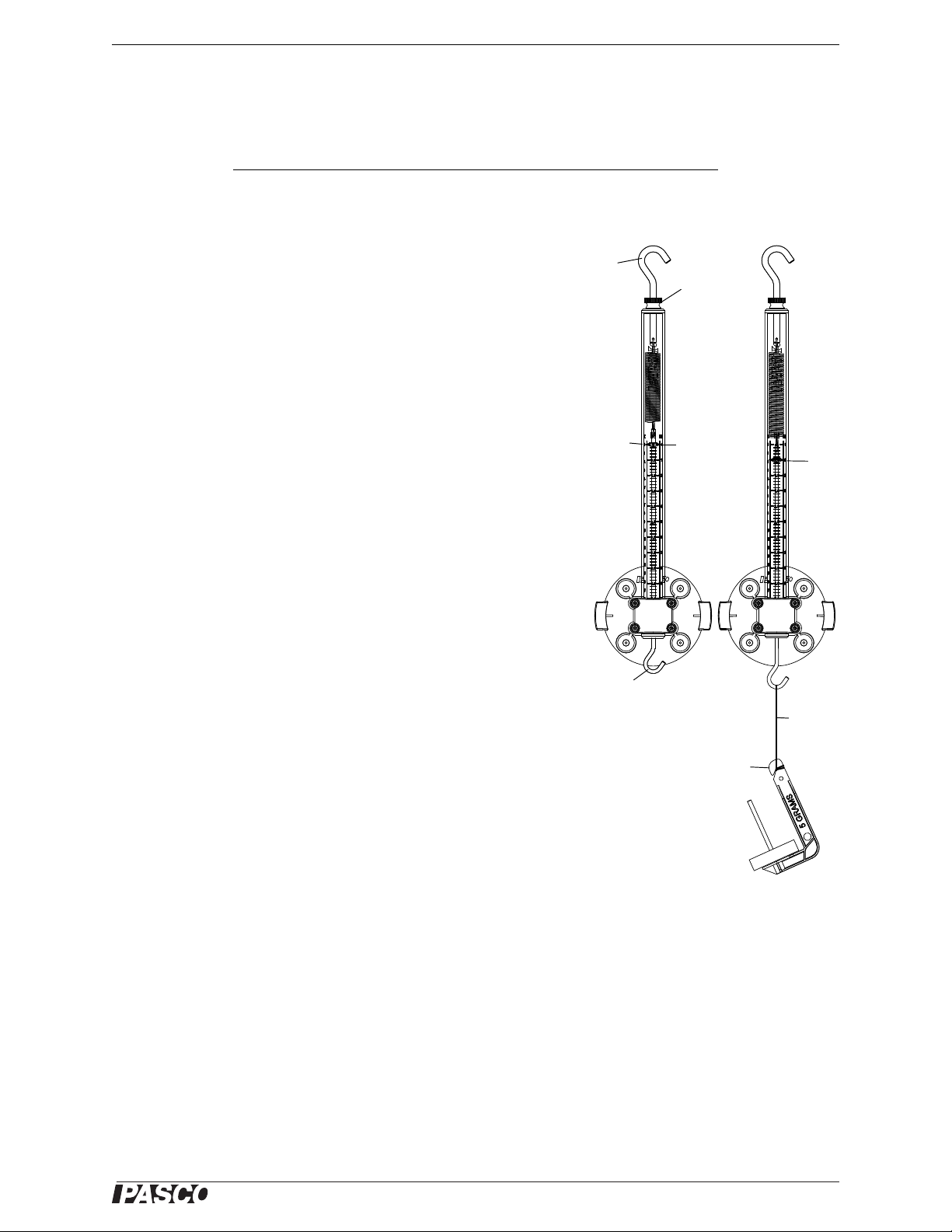
Top
hook
Thumbnut
Indicator
Zero
mark
Bottom
hook
Figure 1.1: Setup and Procedure
Mass
hanger
10
mm
Thread
Exp. 1: Hooke’s Law—Measuring Force
Equipment Needed
Item Item
Statics Board Mounted Spring Scale
Mass and Hanger Set Thread
Introduction
At a practical level, a force is simply a push or a pull. A force is also a
vector quantity that has magnitude (size) and direction. There are different ways to apply and measure a force. One way to apply a force is to
hang a known mass, and determine the force based on the assumption
that gravity pulls the mass downward toward the center of the earth
with a magnitude F = mg, where m is the known mass and g is the
acceleration due to gravity (9.8 m/s
be expressed as 9.8 N/kg. Another way to apply a force is to pull with a
spring. A spring stretches when it is pulled, and if he amount it stretches
is directly proportional to the applied force, then the spring can be calibrated to measure unknown forces. In this experiment you will use the
known force associated with gravity pulling on calibrated masses to
investigate the properties of the Mounted Spring Scale.
2
). Note that the value of g can also
Hooke’s Law
Hooke’s Law describes the relationship between the amount of force
and the amount of stretch for an “ideal” spring. The law states that the
force and the stretch are directly proportional. In other words, the ratio
of the force divided by the stretch is a constant, k. The constant is called
the “spring constant”.
Setup
Place the Spring Scale on the Statics Board so that the spring hangs vertically in the tube. Do not hang anything on the bottom hook. The indicator must be aligned with the zero mark on the label. To zero the
Spring Scale, loosen the thumbnut at the top of the scale. Turn the top
hook clockwise to lower the indicator, and counter-clockwise to raise
the indicator. Once the indicator is aligned with the zero mark on the
label, tighten the thumbnut.
Procedure
1. Attach a thread to the bottom hook and hang a mass hanger from the thread.
2. Add mass to the mass hanger until the indicator is aligned with the 10 mm mark on the label. Adjust the mass
3. Record the total amount of mass (including the mass hanger) in the data table. Record the uncertainty.
so that the indicator is as close as possible to the mark. Estimate the uncertainty in your measurement. (If you
add or remove 0.5 g, can you see a change? What happens if you add or remove 1 g or 2 g?)
4. Add more mass to the mass hanger until the indicator is aligned with the 20 mm mark on the label and record
the total amount of mass and the uncertainty.
5. Repeat the process to move the indicator down by 10 mm each time until the indicator is aligned with the 80
mm mark. Record the total mass and the uncertainty each time.
012-12876B 11
Page 16

Statics System Exp. 1: Hooke’s Law—Measuring Force
®
Weight - Spring Scale
Weight
---------------------------------------------------- -
X100
Data Table
Spring Displacement (m) Mass (kg) Uncertainty Weight (N)
0.010 m (10 mm)
0.020 m (20 mm)
0.030 m (30 mm)
0.040 m (40 mm)
0.050 m (50 mm)
0.060 m (60 mm)
0.070 m (70 mm)
0.080 m (80 mm)
Calculations
1. Using the formula F = mg, where m is the mass and g is the a cceleration due to gravity, calculate the weight in
newtons for each trial. Record the weight in the data table. (To get the correct force in newtons, you must convert the mass value to kilograms.)
2. On a sheet of graph paper, construct a graph of Weight (N) versus Spring Displacement (m) with Spring Dis-
placement on the x-axis.
3. Draw the line that best fits your data points on the graph. The slope of this line on the graph is the ratio of the
force that stretched the spring divided by the amount of stretch. In other words, the slope is the spring constant, k, for the spring in the Spring Scale.
4. Determine the spring constant, k, from your graph and record the result. Remember to include the units (new-
tons per meter).
Spring constant = _____________________________
Using a Spring Scale to Measure Force
• Hang 160 g (0.160 kg) on the Spring Scale. Calculate the weight based on F = mg. Read the force in newtons
from the Spring Scale.
Weight = _______________ Spring Scale reading = ______________
• How does the measurement from the Spring Scale compare to the actual weight?
• Calculate the percent difference:
Percent Difference = _______________
Questions
1. Hooke’s Law states that the relationship between force and displacement in springs is a linear relationship. If
2. In what way is Hooke’s Law useful when calibrating a spring for measuring forces?
3. On your graph of Weight versus Spring Displacement, did the best fit line go through the origin (zero)? If it
12
Hooke’s Law was not valid, could a spring still be used successfully to measure forces? If so, how?
didn’t, what does that mean?
012-12876B
Page 17
®
Model No. ME-9502 Exp. 2: Adding Forces—Re sultants and Equilibriants
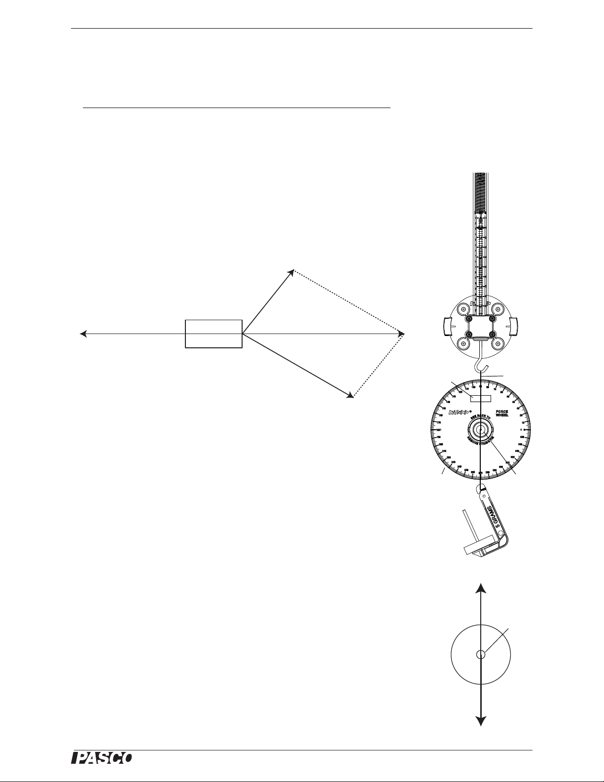
Figure 2.2: Setup
Force
Wheel
Bubble
level
Force
disk
Spring
Scale
Thread
Force
disk
Fg = mg
F
E
= mg
Figure 2.1: Resultant and Equilibriant
F
A
F
B
F
R
F
E
Car
Exp. 2: Adding Forces—Resultants and Equilibriants
Equipment Needed
Item Item
Statics Board Mounted Spring Scale
Force Wheel Large and Small Pulleys
Mass and Hanger Set Thread
Theory
In figure 2.1, Person A and Person B are pulling with forces represented by FA and
F
on a car stuck in the mud. Since these forces are acting on the same point of the
B
car, they are called concurrent forces. Each force is defined both by is direction
(the direction of the vector arrow), and by its magnitude, which is proportional to
the length of the vector arrow. (The magnitude of the force is independent of the
length of the tow rope.)
The total force applied by the two people can be determined by adding vectors F
and F
. The parallelogram method is used in the example. The diagonal of the par-
B
allelogram is called the resultant, F
combination of F
and FB.
A
. It shows the magnitude and direction of the
R
Because the car is not moving, the net force on the car must be zero. The friction
between the car and the mud is equivalent to the resultant force, F
opposing force is called the equilibriant, F
the resultant, F
Setup
, and it has the opposite direction of the resultant.
R
. This force has the same magnitude as
E
. This equivalent
R
Set up the Spring Scale and Force Wheel on the Statics Board as shown. Twist the
Force Wheel until the bubble level shows that the Force Wheel is level. Attach one
of the threads from the force disk (inner part of the String Tie) in the center of the
Force Wheel to the bottom hook of the Spring Scale. Connect a second thread to a
mass hanger (let the third thread dangle). Add 80 g (0.080 kg) to the mass hanger.
Adjust the Spring Scale up or down so that the force disk is centered in the Force
Wheel. The mass hanger applies a force downward, F
ity, where m is the total mass of the mass hanger). When the force disk is centered,
the system is in equilibrium, so the downward force F
equal and opposite force, the equilibriant, F
F
, is applied by the Spring Scale.
E
. In this case, the equilibriant force,
E
= mg (the force due to grav-
g
must be balanced by an
g
A
012-12876B 13
Page 18
Statics System Exp. 2: Adding Forces—Resultants and Equilibriants
®
Figure 2.3: Find the Equilibriant
Small
Pulley
Small
Pulley
Large
Pulley
Force
Wheel
Force
disk
Spring
Scale
F
1
F
2
F
E
Vector diagram
1
2
E
M
2
M
1
Zero
line on
the
Force
Wheel
Procedure: Two Forces
1. Add or remove 0.5 g to the mass hanger. Did the force disk move away from the center position? How much
can you change the mass on the mass hanger without changing where the force disk is centered?
2. What are the magnitude and direction of F
• F
: Magnitude ________________ Direction ________________
g
, the gravitational force applied by the hanger, where Fg = mg?
g
3. Use the Spring Scale and Force Wheel to determine the magnitude and direction of F
• F
: Magnitude ________________ Direction ________________
E
Procedure: Three Forces
1. Attach the Large Pulley and the two Small
Pulleys to the Statics Board and move the
Spring Scale as shown in the figure.
2. Attach threads to the bottom hook of the
Spring Scale and to mass hangers over the
Small Pulleys.
3. Add 30 g (0.030 kg) to the upper mass
hanger and add 50 g (0.050 kg) to the lower
mass hanger.
4. Adjust the Large Pulley and the Spring
Scale so that the force disk is centered in the
Force Wheel.
, the equilibriant.
E
5. How much can you change the mass on the
hangers and still leave the force disk centered in the Force Wheel?
Data
Record the values of the hanging masses M1 and
M
(including the mass of the mass hangers), the
2
magnitude in newtons of the forces F
F
, and the angles 1, 2, and E with respect to
E
the zero-degree line on the Force Wheel..
Mass (kg) Force (N) Angle (°)
M
1
M
2
F
1
F
2
F
E
1
2
E
, F2, and
1
14
012-12876B
Page 19

®
Model No. ME-9502 Exp. 2: Adding Forces—Re sultants and Equilibriants
Analysis
1. On a separate piece of graph paper, use the values you recorded in the table to construct a vector diagram for
F
, F2, and FE. Choose an appropriate scale, such as 2.0 centimeters per newton, and make t he l engt h of eac h
1
vector proportional to the magnitude of the force. Label each vector and indicate the magnitude of the force it
represents.
2. On your vector diagram, use the parallelogram method to draw the resultant of F
F
. Measure the length of FR to determine the magnitude of the resultant force and record this magnitude on
R
and F2. Label the resultant
1
your vector diagram.
3. On your diagram, measure the direction of F
angle
.
R
relative to the horizontal axis of your diagram and label the
R
Questions
1. Does the magnitude of the equilibriant force vector, FE, exactly balance the magnitude of the resultant force
vector, F
2. Ho w does the dire ction of the equilibriant force vector, F
tor, F
. If not, what are some possible reasons for the difference?
R
?
R
E
, compare to the direction of the resultant force vec-
Extension
Vary the magnitudes and directions of F1 and F2 and repeat the experiments.
012-12876B 15
Page 20

Statics System Exp. 2: Adding Forces—Resultants and Equilibriants
®
16
012-12876B
Page 21
®
Model No. ME-9502 Exp. 3: Resolving Forces—Components
M
1
M
2
M
1
F
-F
x
-F
y
Spring
Scale
Pulley
Pulley
Force
Wheel
Force
disk
Figure 3.1: Setup
Exp. 3: Resolving Forces—Components
Equipment Needed
Item Item
Statics Board Mounted Spring Scale
Force Wheel Pulleys (2)
Mass and Hanger Set Thread
Theory
In experiment 2, you added concurrent forces vectorially to determine the magnitude and direction of the combined forces. In this experiment, you will do the reverse: you will find two forces which, when added together,
have the same magnitude and direction as the original force. As you will see, any force vector in the X-Y plane can
be expressed as a vector in the x-direction and a vector in the y-direction.
Setup
Set up the equipment as shown in the figure. As
shown, create a force vector F by hanging a
mass, M
center of the Force Wheel over a pulley.
, on a thread from the force disk in the
1
Set up the Spring Scale and a pulley so that the
thread from the Spring Scale is horizontal from
the bottom of the pulley to the force disk. Hang a
second mass hanger directly from the force disk
in the center of the Force Wheel.
Now pull the Spring Scale toward or away from
the pulley to adjust the horizontal or x-component of the force, F
on the vertical mass hanger , M
tical or y-component of the force, F
. Adjust the amount of mass
x
, to adjust the ver-
2
. Adjust the
y
x- and y-components in this way until the force
disk is centered in the Force Wheel.
Note: These x- and y-components are actually
the x- and y-components of the equilibriant, F
,
E
of the force F, rather than the components of F
itself.
Procedure 1
1. Calculate and record the magnitude of F (based on F = mg). Use the Force Wheel to measure the angle of F
and then record the angle.
• Magnitude, F = _________________ Angle, = ____________________
2. Record the magnitude of the x-component of the equilibriant of F and calculate and record the y-component
of the equilibriant of F.
• X-component = _________________ Y-component = ____________________
012-12876B 17
Page 22
Statics System Exp. 3: Resolving Forces—Components
®
F
Fx = F cos
F
y
= F sin
O
X
Figure 3.2: Vector components
F
R
Rx2Ry
2
+=
R
R
y
R
x
----- -
atan=
3. What are the magnitudes of F
• F
= _________________ Fy = ____________________
x
and Fy, the x- and y-components of F?
x
4. Change the magnitude and direction of the force vector F and repeat the experiment.
5. Record the magnitude and angle of the new force vector, F, and the magnitudes of F
• Magnitude, F = _________________ Angle, = ____________________
• F
= _________________ Fy = ____________________
x
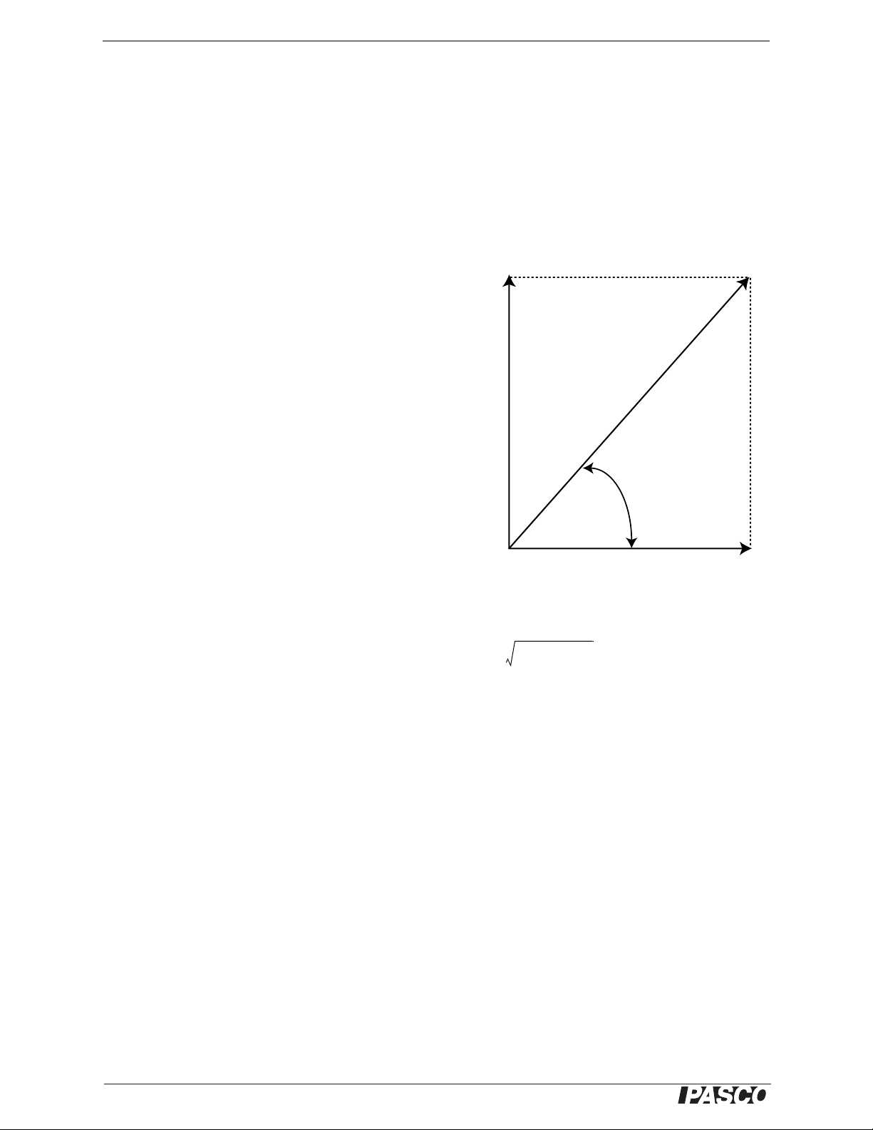
Background
Why use components to specify vectors? One
reason is that using components makes it easier
to add vectors mathematically. The figure shows
the x- and y-components of a vector of length F,
and an angle with respect to the x-axis. Since
the components are at right angles to each other,
the parallelogram used to determine their resultant is a rectangle. Using right triangle AOX, the
components of F can be calculated:
and Fy.
x
• F
, the x-component of F is F cos
x
• F
, the y-component of F is F sin
y
If you want to add several vectors, find the x- and
y-components for each vector. Add all the
x-components together and all the y-components
together. The resulting values are the x- and
y-components for the resultant. The magnitude of the resultant, F
the resultant’s x-component (R
) and the y-component (Ry).
x
, is the square root of the sum of the squares of
R
The angle of the resultant is the arctangent of the y-component divided by the x-component.
Procedure 2
Make sure that the Force Wheel is level. Set up a new force, F. Put one thread from the force disk over a pulley and
tie a mass hanger to the end of the thread. Add mass to the mass hanger.
1. Calculate and record the magnitude of the force, F, that you set up with the pulley and mass hanger. Use the
Force Wheel to determine the angle.
• Magnitude, F = _________________ Angle, = ____________________
2. Calculate the magnitudes of F
and F
• F
= _________________ Fy = ____________________
x
= F sin .)
y
3. Now, set up the Spring Scale with a pulley and a thread from the force disk so it can apply the x-component,
F
, of the new force F. Adjust the Spring Scale so that it pulls the force disk horizontally by the amount, Fx.
x
4. Next, attach a mass hanger to the third thread from the force disk so the thread hangs vertically. Add mass to
the hanger so it pulls the force disk vertically by the amount, F
18
and Fy, the x- and y-components of the new force, F. (Remember, Fx = F cos
x
.
y
012-12876B
Page 23
®
Model No. ME-9502 Exp. 3: Resolving Forces—Components
F
1
F
2
F
3
NOTE: The diagram is
not to scale.
Figure 3.3: Extension vectors
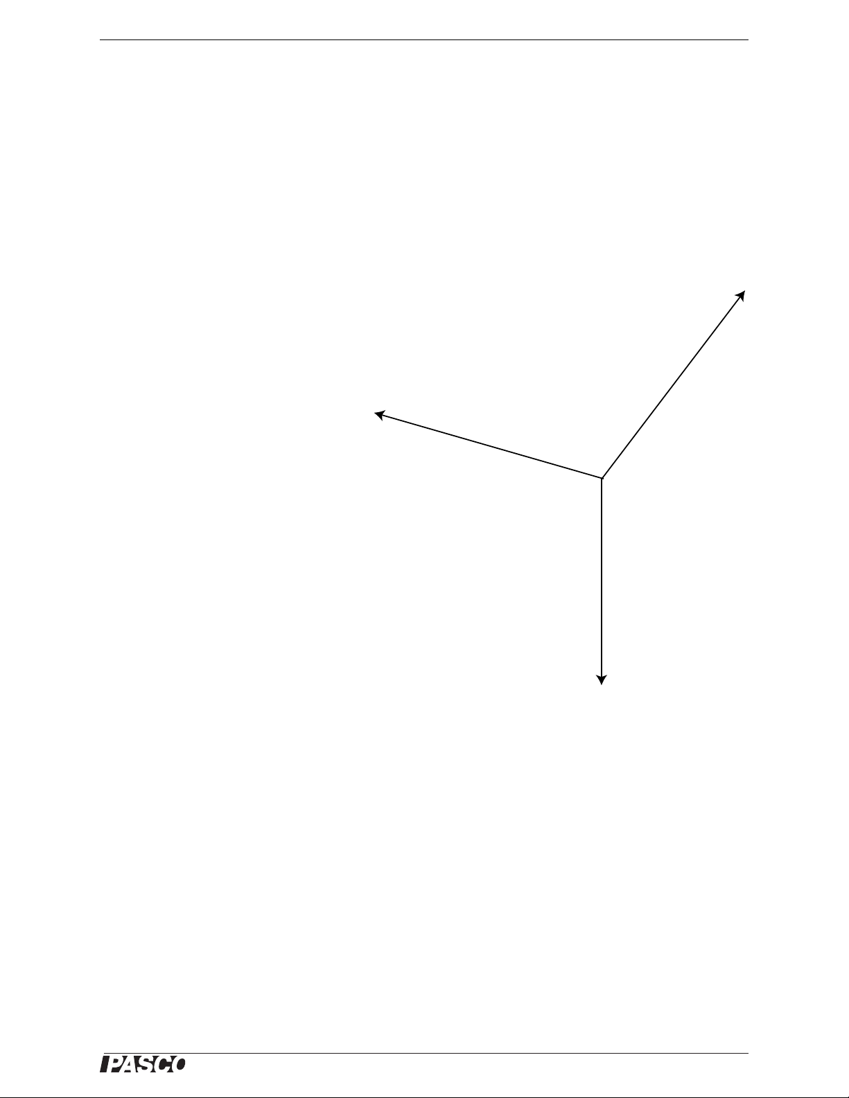
Question
1. Is the force disk at equilibrium in the center of the Force Wheel?
2. Why or why not?
Extensions
1. Generally it is most useful to find the components of a vector along perpendicular axes, as you did above.
However, it is not necessary that the axes be perpendicular. If time permits, try setting up the equipment to
find the components of a vector along non-perpendicular axes. Use pulley to redirect the component forces to
non-perpendicular directions.
2. The figure shows a classic vector combination. For the force disk to be in
equilibrium, the x-components of force
F
and force F2 must be equal and
1
opposite, and the y-components of F
and F
must add to equal the magni-
2
tude of force F
, the vertical force. Set
3
up the equipment so that the Spring
Scale applies force F
. Once the sys-
1
tem is in equilibrium, determine the xand y-components of the vectors and
compare them.
1
3. For the setup in the figure, change the
angles of F
are closer to the x-axis. Calculate the
x-components and notice the change.
What happens to the x-components as
the two forces become closer and
closer to parallel? What amount of
force would be needed if F
were both horizontal?
and F22 so that the vectors
1
and F2
1
012-12876B 19
Page 24

Statics System Exp. 3: Resolving Forces—Components
®
20
012-12876B
Page 25
®
Model No. ME-9502 Exp. 4: Torque—Parallel Forces
A
F
R
Figure 4.1: Non-concurrent forces
Object
F
1
F
1
Figure 4.2: Balance Arm
Base
Thumbscrew
Bubble level
Beam
Pivot
Scale
Figure 4.3: Setup
Angle
Indicator
Protractor 2
M
1
M
2
Protractor 1
Thread
Mass
hanger
Exp. 4: Torque—Parallel Forces
Equipment Needed
Item Item
Statics Board Balance Arm and Protractors
Mass and Hanger Set Thread
Theory
In experiment 2, you found resultants and equilibriants
for concurrent forces—forces that act upon the same
point. In the real world, forces are often not concurrent.
They act upon different points on an object. In the figure, for example, two forces are pulling on different
points of an object. Two questions can be asked:
1. In which direction will the object be accelerated?
2. Will the object rotate?
If the two forces were both applied at point A, the resultant would be the force vector shown, F
. In fact, FR points
R
in the direction in which the object will be accelerated. (This idea will be investigated further in later experiments,)
What about question 2? Will the object rotate? In this experiment you will begin to investigate the types of forces
that cause rotation in physical bodies. In doing so, you will encounter a new concept—torque.
Setup
Mount the Balance
Arm near the center of
the Statics Board.
Level the Beam
Loosen the thumbscrew and adjust the beam so that the zero mark on the beam is aligned with the indicator marks
on the pivot. When the beam is level, the bubble in the bubble level will be midway between the two lines on the
level.
Add the Protractors
First, find the mass of two
of the protractors and
record the masses. (Note
that you can use the Spring
Scale to measure the mass.)
• Protractor 1 =
__________
• Protractor 2 =
__________
Loosen the thumbscrews on the two protractors and slide one onto each end of the beam. Tie a mass hanger to the
thread on the angle indicator of each protractor.
012-12876B 21
Page 26
Statics System Exp. 4: Torque—Parallel Forces
®
d
1
d
2
M
1
M
2
Figure 4.4: Measuring Torques
center of
protractor 1
center of
protractor 2
pivot
M
1
M
2
d
1
d
2
Figure 4.5: More Torques
center of
protractor 1
pivot
center of
protractor 2
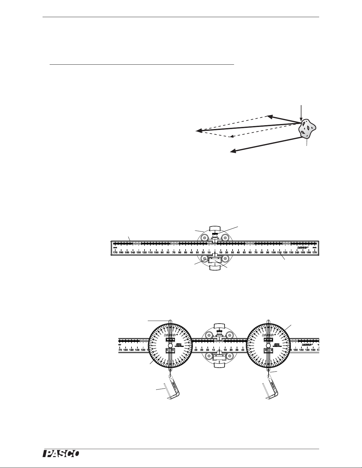
Procedure: Equal Distance, Equal Mass
Position one of the protractors near one end the beam and tighten its thumbscrew to hold it in place. Adjust the
position of the other protractor until the beam is perfectly balanced, and then tighten its thumbscrew to hold it in
place.
1. Measure d
and d2, the distances
1
from the pivot to the center of each
protractor.
•d
= _______________
1
•d
= _______________
2
2. Add a 50-gram mass to each mass
hanger.
• Is the beam still balanced?
3. Add an ad ditional 20-gram to one of the mass hangers.
• Can you restore the balance of the beam by repositioning the other protractor and mass hanger?
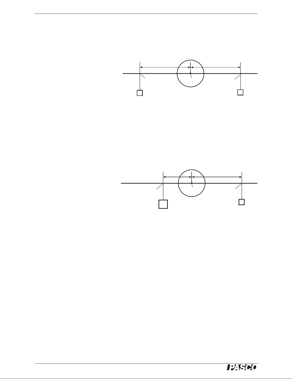
Procedure: Unequal Distance, Unequal Mass
Position one of the protractors approximately halfway between the pivot point
and the end of the beam and tighten its
thumbscrew to hold it in place. Add 75
grams of mass to the mass hanger, M
.
1
Place various masses on the other mass
hanger (M
) and slide it along the beam
2
as needed to rebalance the beam.
1. At the first balanced position, measure the total mass, M
and M2, on each side of the pivot (protractor, mass
1
hanger, added masses) and record the masses in the data table.
2. Measure the distances, d
and d2, between the centers of the protractors and the pivot and record the values in
1
the data table.
3. Take measurements for five more different valu es of M
and record your results in the data table. Be sure to
2
include the units of your measurements.
4. If there is time, vary M
and repeat the procedure.
1
• Reminder: For accurate results, include the mass of the protractor, mass hanger, and added masses when measuring M
and M2.
1
Calculations
Calculate the gravitational force (weight = mg) produced by the total mass on each side of the beam for each case.
Calculate the torques,
of the net force and the lever arm. Since the distance and the direction of the force are at right angles in this experiment, the torque, , is F d (where F
balanced position of the beam.
22
and 2, on each side of the beam for each case. Remember, torque, , is the cross product
1
= mg). Record your calculated values of weight, Fg, and torque, , for each
g
012-12876B
Page 27

®
Model No. ME-9502 Exp. 4: Torque—Parallel Forces
Data Table
Case Total Mass
M
(kg)
1
1
2
3
4
5
6
Weight
F1 (N)
Distance
d1 (m)
Torque
1 = F1 d
1
Total Mass
M
(kg)
2
Weight
F2 (N)
Distance
d2 (m)
2 = F2 d
Questions
1. From your results, what mathematical relationship must there be between 1 and 2 in order for the beam to be
balanced?
2. What torque is exerted on the balance beam by the upward pull of the pivot point?
Extension
If you have time, try adding a third Protractor and Mass Hanger to the beam on the same side of the beam as the
second Protractor.
Torque
2
Question
What relationship must there be between
protractors and mass hangers?
, 2, and 3 in order for the beam to be balanced when there are three
1
012-12876B 23
Page 28

Statics System Exp. 4: Torque—Parallel Forces
®
24
012-12876B
Page 29
®
Model No. ME-9502 Exp. 5A: Center of Mass
Support
Center of mass
Object
Figure 5.1: Equipment Setup
M
1
M
2
Pivot
base
Protractor
Angle
Indicator
Exp. 5A: Center of Mass
Equipment Needed
Item Item
Statics Board Balance Arm and Protractors
Asymmetrical Plate Thread
Mass and Hanger Set
Theory
Gravity is a universal force; every bit of matter in the universe is attracted to every other bit of matter. Therefore,
when the Balance Arm is supported by the pivot, every bit of matter in the Balance Arm is attracted to every bit of
matter in the Earth.
Fortunately , the sum of all these individual gravitational forces produces a single resultant. This resultant acts as if
it were pulling between the center of the Earth and the center of mass of the Balance Arm. The magnitude of the
force is the same as if all the matter of the Earth were located at the center of the Earth, and all the matter of the
Balance Arm were located at the center of mass of the Balance Arm.
An object thrown so that it rotates tends to rotate about its center of mass,
and the center of mass follows a parabolic path. An object whose center of
mass is above a support tends to remain in rotational equilibrium (balanced on the support). In this experiment you will use your knowledge of
torque to understand and locate the center of mass of an object.
Setup
Measure and record the
mass of the beam.
Next, find the mass of
two of the protractors
and record the masses.
(Note that you can use
the Spring Scale to
measure the mass.)
• Beam = ________
• Protractor 1 = __________
• Protractor 2 = __________
Loosen the thumbscrews on the two protractors and slide one onto each end of the beam so each protractor is at the
165 mm mark. Tie a mass hanger to the thread on the angle indicator of each protractor
Mount the Balance Arm near the center of the Statics Board.
Record the total mass of the beam plus protractors plus mass hangers (5 grams each).
• Mass of system = _____________
012-12876B 25
Page 30

Statics System Exp. 5A: Center of Mass
®
Pivot
Center of mass
of the beam
F
2
F
3
F
1
Figure 5.2: Torques and the Center of Mass
Level the Beam and Mark the Center of Mass
Loosen the thumbscrew and adjust the beam so that the indicator marks on the pivot are aligned with the zero mark
on the beam. If necessary, adjust the positions of the two protractors until the bubble in the bubble level is midway
between the two lines on the level. Once the beam is balanced and level, tighten the thumbscrews to hold the protractors and beam in place.
Put a pencil mark on the beam to indicate the center of mass of the system. All of the mass of the system (beam,
protractors, mass hangers) acts as if it is concentrated at the center of mass.
Once the beam is in balance, the force at the pivot point must be the equilibriant of the total gravitational force acting on the beam. Since the beam does not rotate, the gravitational force and its equilibriant must be concurrent
forces.
Experiment
1. Why would the Balance Arm necessarily rotate if the resultant of the gravitational forces and the force provided by the pivot were not concurrent forces?
• Think of the Balance Arm as a collection of many small hanging masses. Each hanging mass is pulled down
by gravity and therefore produces a torque about the pivot point of the Balance Arm.
2. What is the relationship between the sum of the clockwise torques about the center of the mass and the sum of
the counterclockwise torques about the center of mass? Explain.
• Add 50 grams to one mass hanger and 100 grams to the other mass hanger. Loosen the thumbscrew on the
beam and slide the beam through the pivot until the beam and masses are balanced. Tighten the thumbscrew.
• The pivot is still supporting everything (beam, protractors, mass hangers, and hanging masses), but at the new
center of mass of the system–the pivot point.
3. Calculate the three torques,
and
provided by the three forces
3
F
, F2, and F3 acting about the new
1
, 2,
1
pivot point position. Be sure to indicate whether each torque is clockwise (cw) or counterclockwise (ccw).
Position Mass (kg) Force (F = mg) Distance (m) Torque ( = F d)
1 0.050
2 0.100
3
4. Are the clockwise and counte rclockwise torques balanced?
• Remove the 50 gram mass from the left hand mass hanger, but leave the hanger and protractor in place.
(Removing the mass effectively removes F
balances the torque provided by F
26
and the beam is level again.
2
). Reposition the beam in the pivot until the torque provided by F3
1
012-12876B
Page 31

®
Model No. ME-9502 Exp. 5A: Center of Mass
Mass
hanger
Asymmetrical
Plate
Force Sensor
Mount
Thread
Rod
Figure 5.3: Finding the
Center of Mass
• Recalculate the torques about the pivot point.
Position Force (F = mg) Torque ( = F d)
2
3
5. Are the torques balanced?
Asymmetrical Plate
Replace the Balance Arm with the Force Sensor Mount. Hang the Asymmetrical Plate from the rod on the Force Sensor Mount.
Since the force of the rod acting on the plate is the equilibriant to the sum of the
gravitational forces acting on the plate, the line of force exerted by the rod must
pass through the center of the mass of the plate. Loop a piece of thread over the
rod and attach a mass hanger to the end of the thread.
Use a pencil or a “dry erase” pen to draw a line on the Asymmetrical Plate that
marks the position of the thread on the plate.
Remove the thread and mass hanger. Hang the plate from a different hole. Put
the thread and mass hanger back on the rod. Draw a new line on the plate that
marks the position of the thread.
Repeat the process for a third different hole. Draw a third line on the plate.
6. Does the line showing where the thread is hanging pass through the center
of mass of the plate?
7. Would this method work for a three dimensional object? Why or why not?
Extension
Remove the thread and plate from the rod. Try to balance the Asymmetrical Plate on your finger by placing the tip
of you finger under the point where the three drawn lines intersect. What happens?
012-12876B 27
Page 32

Statics System Exp. 5A: Center of Mass
®
28
012-12876B
Page 33

®
Model No. ME-9502 Exp. 5B: Equilibrium of Physical Bodies
Figure 5.4: Non-concurrent,
non-parallel forces
Object
F
1
F
2
F
3
M
1
M
2
F
1
F
2
F
3
F
4
Spring
Scale
Force
diagram
Point of
suspension
Center of mass
of the beam
C.O.M.
Figure 5.5: Equipment Setup
Exp. 5B: Equilibrium of Physical Bodies
Equipment Needed
Item Item
Statics Board Balance Arm and Protractors
Pulley (1) Mounted Spring Scale
Mass and Hanger Set Thread
Theory
Any force acting on a body may produce both translational motion
(movement of the center of mass of the body in the direction of the force)
and rotational motion (rotation about a pivot point).
In this part of the experiment you will investigate the interplay between
forces and torques by examining all the forces acting on a body in physical equilibrium.
Setup
Find the center of mass of the balance beam and mark it with a pencil. Use the Spring Scale, mass hangers, and
three protractors on the Balance Arm to set up the equipment as shown.
By supporting
the Balance
Arm from the
Spring Scale,
you can now
determine all
the forces acting on the Balance Arm.
As shown in
the diagram,
these forces
include F
weight of the
mass, M
the weight of
the mass M
F
, the weight
3
1
, F2,
1
, the
,
2
of the balance
beam acting
through its center of mass, and
F
, the upward pull of the Spring Scale.
4
Experiment
Fill in the data table listing M (in kilograms), F (in newtons), d (the distance in meters from the applied force to the
suspension point), and (the torque acting about the point of suspension in newton • meters. Indicate whether each
torque is clockwise (cw) or counterclockwise (ccw)
012-12876B 29
Page 34

Statics System Exp. 5B: Equilibrium of Physical Bodies
®
F
1
F
2
F
3
F
4
d
1
d
2
d
3
d
4
Figure 5.6: Change the Origin
Origin
Data Table.
Position mass (M) force (F) distance (d) torque ()
1
2
3
4—
Calculations
1. Calculate and record the sum of the clockwise and counterclockwise torques.
= _________________________
cw
• Are the torques balanced?
2. Calculate and record the sum of the upward and downward forces.
F
= _________________________ F
up
= _______________________
ccw
= _______________________
down
• Are the translational forces balanced?
3. On the basis of your answers to the questions, what conditions must be met for a physical body to be in equilibrium (no acceleration)?
Change the Origin
In measuring the torques the first time, all the distances were measured from the point of suspension of the Balance Arm. This measures the tendency of the beam to rotate about this point of suspension. You can also measure
the torques about any other point, on or off the beam. Using the same forces as you used before, re-measure the
distances, measuring from the left end of the balance beam as shown in the diagram.
Recalculate the
torques to
determine the
tendency of the
beam to rotate
about the left
end of the
beam.
Record your
data in the second table. As
before, indicate whether each torque is clockwise (cw) or counterclockwise (ccw).
30
012-12876B
Page 35

®
Model No. ME-9502 Exp. 5B: Equilibrium of Physical Bodies
Data Table: Change the Origin.
Position force (F) distance (d) torque ()
1
2
3
4
Calculations
1. Calculate and record the sum of the clockwise and counterclockwise torques.
= _________________________
cw
= _______________________
ccw
• Are the torques balanced?
Extension
Use a pulley, hanging mass, and a thread to produce an additional upward force at one end of the beam. You may
need to use tape to secure the thread to the beam.) Adjust the positions of the remaining hanging masses and the
Spring Scale to bring the beam back into balance so it is level horizontally.
• Are all the forces balanced, both for translational and rotations motion?
• Diagram your setup and show your calculations on a separate sheet of paper.
012-12876B 31
Page 36

Statics System Exp. 5B: Equilibrium of Physical Bodies
®
32
012-12876B
Page 37

®
Model No. ME-9502 Exp. 6: Torque—Non-Paralle l Forces
Figure 6.1: Torque
F
d
F
Pivot
point
Lever
arm
d
Fd sin=
Exp. 6: Torque—Non-Parallel Forces
Equipment Needed
Item Item
Statics Board Balance Arm and Protractors
Pulley Mounted Spring Scale
Mass and Hanger Set Thread
Theory
In a previous experiment, you investigated torques
appled to the Balance Arm and discovered that when
the torques about the point of rotation are balanced, the
beam remains balanced. All the forces in that experiment were perpendicular to the beam and parallel to
each other. What happens when one or more of the
forces is not perpendicular to the beam?
It turns out that the formula for torque can be generalized to account for this case. Torque is the cross product of the force vector and the lever arm where the lever arm
is the distance from the pivot point to where the force is applied. The generalized formula is:
where F is the magnitude of the force vector, d is the distance from the pivot point to the point at which the force
is applied (that is, the “lever arm”), and is the angle between the force vector, F, and the lever arm, d. Note that
F sin is F
is d
perpendicular distance, d
, the component of the force vector, F, that is perpendicular to the lever arm, d. Note also that d sin
the component of the lever arm, d, that is perpendicular to the force vector, F. In other words, d sin is the
, from the pivot point to the line of force.
Setup
Mount the Balance Arm on the left half of the Statics Board. Adjust the beam so that the zero marks on the beam
align with the indicator marks on the pivot.
Put a protractor on each end of the beam (for example, between 130 and 140 mm from the pivot). Adjust the position of the protractors if necessary so that the beam is balanced and level.
012-12876B 33
Page 38

Statics System Exp. 6: Torque—Non-Parallel Forces
®
M
2
Figure 6.2: Equipment Setup
Spring
Scale
Pulley
Protractor
Beam
M
2
F
2
F
1
d
2
d
1
Pivot point
Figure 6.3: Schematic
12–12+2
Suspend a mass, M
, from one protractor. Mount the Spring Scale on the Statics Board and connect it to the other
2
protractor using a thread and a Pulley as shown.
Procedure
1. Measure d1 and d2 and record the values.
2. Record the total mass, M
tude of the force, F
, and the magni-
2
(weight of the hanging
2
mass). Use your measured values to calculate the torque,
, produced by the force, F2.
2
Be sure to include the units for each value.
d1 (m) d2 (m) M2 (kg) F2 (N) (N•m)
• By moving the pulley, you can adjust the angle of the force, F
. Note that when you move the pulley, you also
1
need to move the Spring Scale in order to keep the thread perfectly vertical between the Spring Scale and the
pulley.
3. Set the angle of F
toward or away from the pulley as needed so that the magnitude of F
to each of the values shown in the table below. At each angle, move the Spring Scale
1
is sufficient to balance the beam.
1
Record the force reading on the Spring Scale in newtons.
Angle F
30°
40°
50°
60°
(N) 1 = F1d1 sin
1
34
70°
80°
012-12876B
Page 39

®
Model No. ME-9502 Exp. 6: Torque—Non-Paralle l Forces
F
1
F
2
O
F
1
O
O
F
2
d
2
d
1
d
d
d
1
d
2
Line of force
Line of
force
Pivot
point
Figure 6.4: Non-Parallel Forces
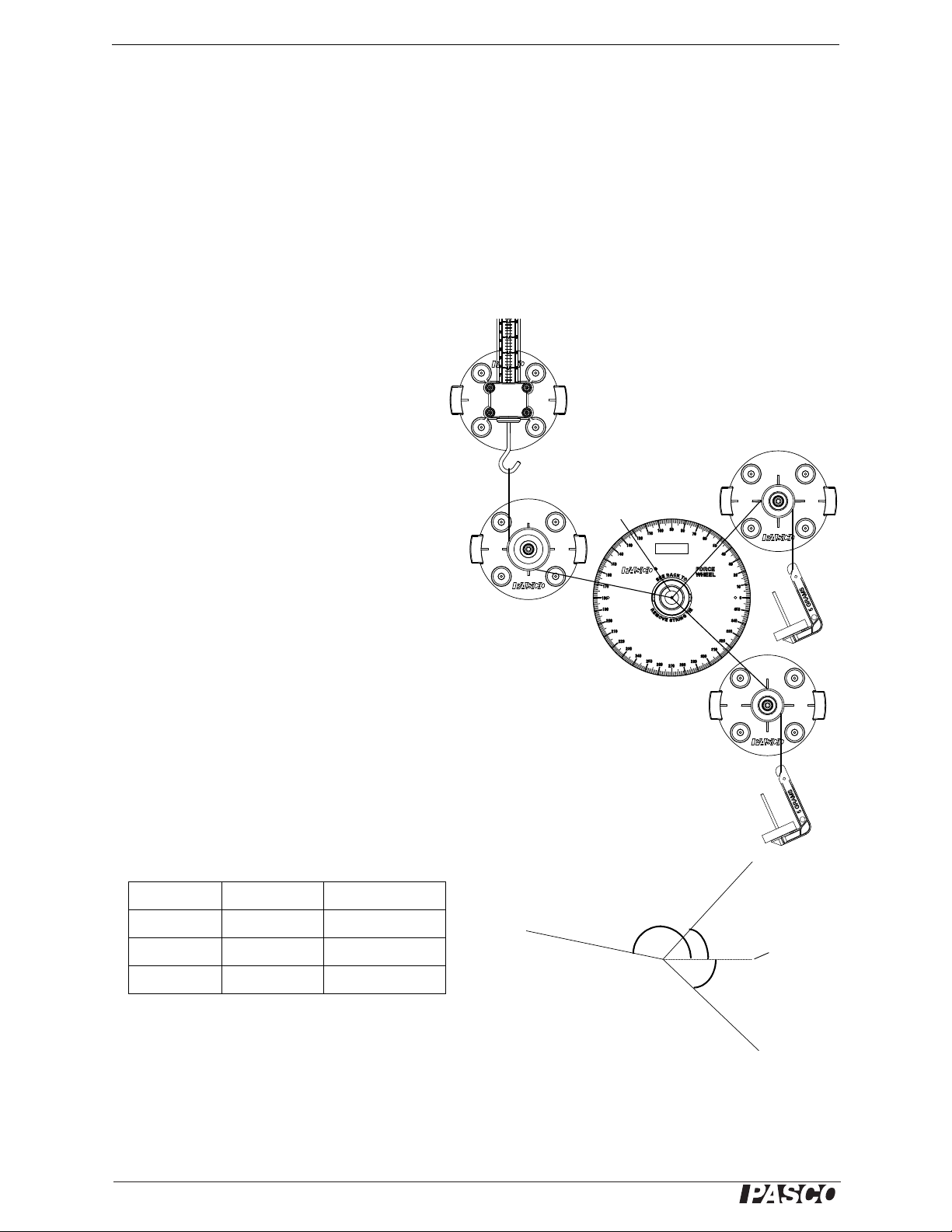
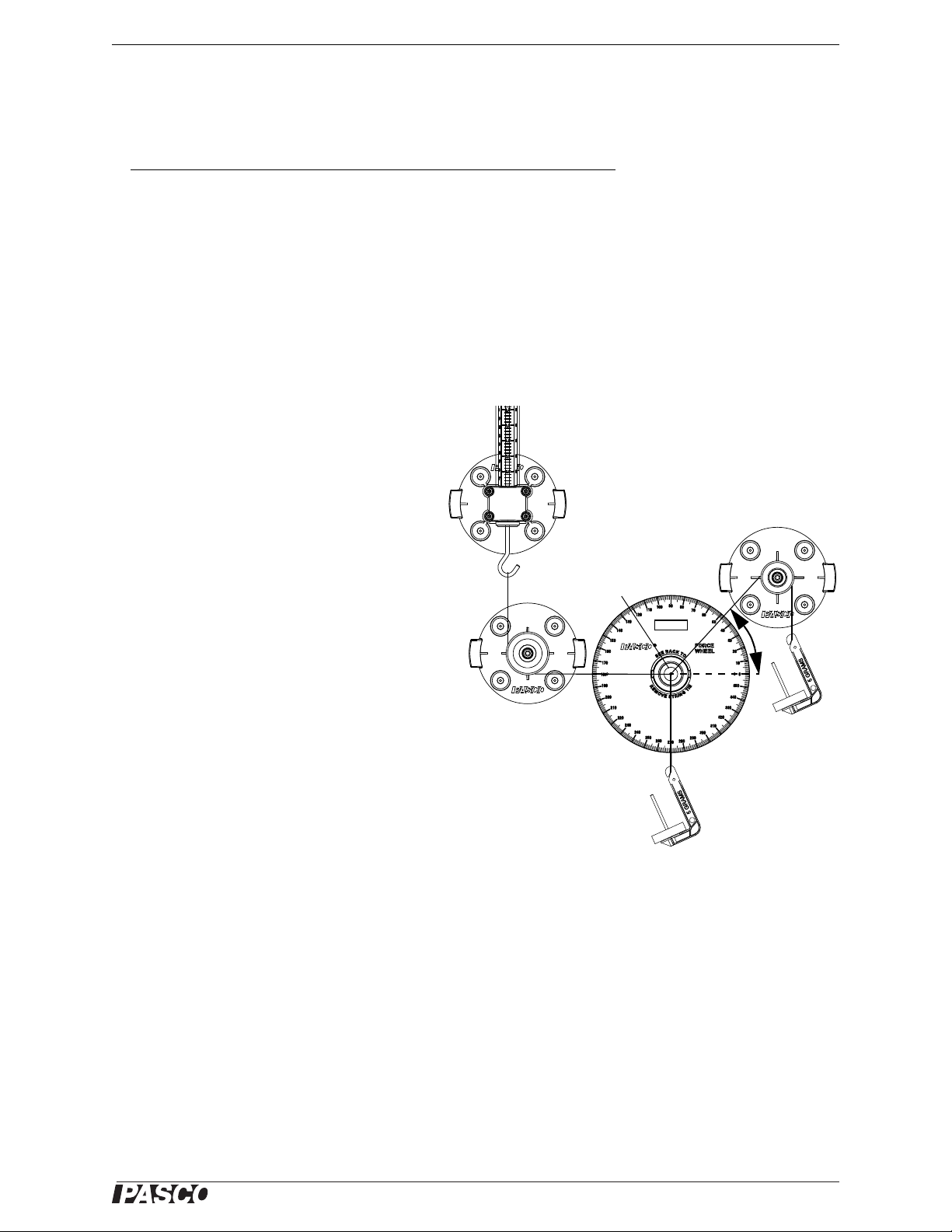
Figure 6.5: Using the Torque Wheel
O
d
1
d
1
F
1
Line of
force
4. Perform the calculations to determine the torque, 1, provided by the Spring Scale, and the percent difference
between
and 2. [The percent difference is the difference of the two torques divided by the average of the
1
two torques.]
• T o provide a consistent mathematical definition of torque,
and 2 must be determined according to the same
1
formula.
5. Apply the generalized definition of torque ( = F d sin ) to the calculation of
What is the angle between the force, F
, and the lever arm, d2?] Does the calculated value using the general-
2
ized definition change the results?
Analyzing Non-Parallel Forces
Imagine two non-parallel forces acting on an object at different distances
from its pivot point. The figure shows a diagram for a calculation of
torque provided by two non-parallel forces. The force F
torque
produces a torque
about the point O with a magnitude of F1 d1 sin 1. The force F2
1
about the point O with a magnitude of F2 d2 sin 2.
2
However, it would be misleading to simply add the two torques together
to determine the total torque because
and 2 cause rotation about point
1
O in opposite directions. When adding two or more torques, add together
the magnitudes of all the torques that tend to cause clockwise rotation,
then add together the magnitudes of all the torques that tend to cause
counterclockwise rotation. For the system to be balanced, the sum of the
clockwise torques must equal the sum of the counterclockwise torques.
Remember that the perpendicular distance, d
, from the pivot point to the
force is equal to d sin and that the angle is measured between the lever
arm, d, and the line of force.
produces a
1
in step 2 previously. [Hint:
2
Torque Wheel
A Torque Wheel provides an easy method for creating an equilibrium
among several non parallel forces. Figure 6.5 shows a force F applied at
an angle to the line from the center of the Torque Wheel to the point of
application of the force. The torque can be calculated as = F d sin .
However, as shown, d sin is just the perpendicular distance, d
between the center of the Torque Wheel and the line of force, when that
line is extended far enough.
Imagine a To rque Wheel with tw o non-parallel forces. The angle
between the force F
tance d
fore, the torque
The radial scale on the Torque Wheel label allows you to measure the
perpendicular distance from the pivot point to the line of force. Each
concentric circle on the label is 2 mm larger in radius. Each Torque
Indicator Arm is transparent and has a centerline that shows the line
of force.
and the lever arm d1 is . The perpendicular dis-
from the pivot point O to the line of force is d1 sin . There-
1
1
produced by F1 is F1 d1
,
012-12876B 35
Page 40

Statics System Exp. 6: Torque—Non-Parallel Forces
®
F
1
F
2
F
3
d
1
d
2
d
3
Pivot
point
Torque
Indicator
Arm
Figure 6.6: Set up the Torque Wheel
Torque
Wheel
Radial
scale
Set Up the Torque Wheel
Remove the Balance Arm and set up the
Torque Wheel on the Statics Board as shown
in the diagram. Use pulleys, thread, and hanging masses to apply three torques to the wheel.
Use the radial scale on the T orque Wheel label
to measure the perpendicular distance from
each line of force to the pivot point. Record
the distances in the data table. Calculate and
record the forces. Calculate and record the
torque for each force using = F d
. Be sure
to indicate whether the torque is clockwise or
counterclockwise.
Subtract the sum of the clockwise torques
from the sum of the counterclockwise torques
to determine the total net torque.
Data Table
Force, F (N) Perpendicular Distance, d
1
2
3
(m) Torque,
= F d
(N•m)
Total Torque = ________________
Question
Within the limits of your experimental error, is the total net torque equal to zero when the Torque Wheel is in equilibrium.
Extension
Repeat the procedure with different forces and angles.
36
012-12876B
Page 41

®
Model No. ME-9502 Exp. 7: The Inclined Plane
Figure 7.1: The Inclined Plane
F
F
Object
Inclined
plane
F
Figure 7.2: Equipment Setup
Inclined
Plane
Pulley
Spring
Scale
Cart
100-g
mass
Keep the thread
parallel to the plane.
Exp. 7: The Inclined Plane
Equipment Needed
Item Item
Statics Board Inclined Plane and Cart
Pulley (2) Mounted Spring Scale
Mass and Hanger Set Thread
Introduction
Suppose you must design a ramp with a cable to hold a
heavy object on an inclined ramp. For a given angle of
inclination of the ramp, how much force must the
cable deliver to hold the object on the ramp? How
much force must the ramp be able to support?
You could solve this problem by building ramps and
cable and testing them, or by testing scale models.
Alternatively, you could use your knowledge of forces
and vectors to solve the problem mathematically. In
the diagram, for example, the weight, F, of the object
on the inclined plane can be resolved into two components: one perpendicular to the plane, F
the plane, F
. The angle, , is the angle of inclination of the inclined plane. In this experiment, you will compare
the mathematical solution with data taken directly from a scale model.
, and one parallel to
Experiment
1. Add a 100-g mass to the cart and measure and record the total mass of the cart. Calculate and record the
weight of the cart-plus-mass.
• total mass of cart = _______________ weight of cart = _________________
2. Set up the Inclined Plane on the Statics Board. Start with the plane at 15°. Put the cart on the Inclined Plane
and use thread connected under a pulley to the Spring Scale to hold the cart in place on the ramp.
012-12876B 37
Page 42

Statics System Exp. 7: The Inclined Plane
®
measured - calculatedmeasured + calculated2 x 100%
Figure 7.3: Normal Force Equipment Setup
The force provided by the Spring Scale, F
the Inclined Plane, F
The calculated component of force that is parallel to the Inclined Plane, F
measured
, equals the component of the force of gravity that is parallel to
calculated
, is F sin
, where is the angle of the plane.
3. Adjust the angle of inclination of the Inclined Plane to each of the values shown in the table. For accurate values, adjust the pulley and Spring Scale so that the thread remains parallel to the plane. At each value, record
the measured value, F
measured
4. At each value, calculate the magnitude of the force parallel to the plane, F
, of the force parallel to the plane.
calculated
= F sin and record the
calculated value.
5. Calculate the percent difference between the measured and calculated values of the force parallel to the plane.
Angle F
15°
30°
45°
60°
75°
*The Percent Difference is the absolulte value of the ratio of the difference of the measured and calculated values, divided by the
average of the measured plus calculated values, converted to a percentage.
measured
F
calculated
= F sin Percent Difference*
Question
How well does the calculated force based on the vector model compare to your measured force?
Normal Force
The force that the Inclined Plane provides to support the cart is called the normal force (a force perpendicular –
“normal” – to the surface.) In the vector model of the force, the component of force that is perpendicular to the
plane, F
surface.
To measure the force of the cart on the Inclined Plane, reset the Inclined Plane to 15°. Replace the Spring Scale
with a mass hanger connected by a thread over the pulley to the cart. Add masses to the mass hanger until the cart
and the hanging mass are in equilibrium. (In other words, the force provided by the tension in the thread equals the
component of the cart’s weight that is parallel to the plane.)
, is F cos . The normal force is equal to the force of the cart on the Inclined Plane, perpendicular to its
38
012-12876B
Page 43

®
Model No. ME-9502 Exp. 7: The Inclined Plane
Figure 7.4: Measure the Normal Force
Tie the thread to the
hole in the post.
Record the total mass of the mass hanger and calculate and record the weight.
• total mass of mass hanger = _______________ weight of mass hanger = _________________
• How does the weight of the mass hanger compare to value of F
calculated
, the component of the cart’s weight
that is parallel to the plane? (See the data table for the value at 15°.)
Add a second pulley to the Statics Board and set up the Spring Balance above the pulley. Tie a thread to the hole at
the top of the post of the cart. Arrange the pulley so the thread from the post is in line with the post, and therefore
is perpendicular to the plane. Arrange the Spring Scale so that the angle of the thread from the pulley up to the
scale is vertical.
Pull the Spring Scale up until the force just barely lifts the mass cart off the Inclined Plane.
Record the value of the Spring Scale as the perpendicular force, F
F
Calculate the value of the perpendicular force as predicted by the vector model, F
value
F
Question
How well does the calculated force based on the vector model compare to your measured force?
measured
calculated
= __________________
= __________________
calculated
= F cos Record the
012-12876B 39
Page 44

Statics System Exp. 7: The Inclined Plane
®
40
012-12876B
Page 45

®
Model No. ME-9502 Exp. 8: Slidin g Fr iction
Plumb bob
Figure 8.1: Equipment Setup
Friction
Block
The thread must
be parallel to the
Inclined Plane.
Level the
Inclined Plane
Mass
Pulley
Mass
Hanger
Exp. 8: Sliding Friction
Equipment Needed
Item Item
Statics Board Inclined Plane and Friction Block
Pulley Mounted Spring Scale
Mass and Hanger Set Thread
Theory
Friction is a force between two objects that resists motion between the two objects. Static friction (or sticking friction) is friction between objects that are not moving relative to each other. For example, static friction can prevent
an object from sliding down an inclined plane. If a net external force on an object is greater than the force of static
friction, the object begins to slide. Sliding friction (or kinetic friction) occurs when two objects are moving relative
to each other. In most cases, the static friction between two objects is greater than the sliding friction between the
two objects. Once sliding begins, if the sliding object’s motion is constant, then the external force equals the force
of sliding friction.
An explanation of friction assumes that surfaces are atomically close to each other over a small fraction of their
overall area. The surfaces that are atomically close to each other will exert retarding forces on each other. This
contact area is proportional to the normal force, and therefore the friction force is proportional to the normal force,
or f F
is called the coefficient of friction, . The friction force is f = F
that is between zero and one for several common surface-to-surface combinations and is determined empirically.
where f is the friction force and FN is the normal force. The ratio of the friction force to the normal force
N
. The coefficient of friction is a unitless number
N
In this experiment you will investigate how the normal force, the contact materials, and the contact area affect the
sliding friction.
Procedure
1. Use the Spring Scale to measure the weight of the Friction Block and then record the value.
•weight, W, of friction block = _________________
2. Mount the Inclined Plane on the Statics Board and use the plumb bob to level the plane. Set the Friction Block
on the Inclined Plane and use thread to connect it over a pulley to a mass hanger as shown.
3. Adjust the pulley so that the thread is parallel to the Inclined Plane.
4. Add or subtract masses on the mass hanger until the Friction Block moves at a very slow, constant speed
when you give it a small push.
012-12876B 41
Page 46

Statics System Exp. 8: Sliding Friction
®
• If the Friction Block stops, the mass is too light. If the Friction Block accelerates, the mass is too heavy.
• The weight of the hanging mass that is sufficient to pull the Friction Block at a constant speed is f
, the force
k
of the sliding (kinetic) friction between the Friction Block and the Inclined Plane.
Variables
Change the following factors and measure the sliding friction force.
• Normal Force: Add mass to the top of the Friction Block to increase the normal force between the block and
the Inclined Plane.
• Contact Material: Two sides of the Friction Block are bare wood. Two other sides are covered with felt.
Compare the sliding friction force for a wood surface to the sliding friction force for an equally sized felt surface.
• Contact Area: The top and bottom surfaces have a larger area than the side surfaces. Compare the sliding
friction force for a larger area to the sliding friction force for a smaller area.
Reminders for each trial:
• Carefully adjust the mass on the mass hanger until the weight of the hanging mass is enough so that the Friction Block moves at a very slow, constant speed after you give it a small push.
• Record the total mass of the Friction Block, M, and the hanging mass, m, (total mass of the mass hanger and
added masses).
• Calculate and record the normal force, F
force, f
(weight of the hanging mass).
k
, of the Friction Block on the Inclined Plane and the sliding friction
N
• Calculate and record the coefficient of friction, , which is the ratio of the sliding friction force, f
the normal force, F
N
Data Table
Trial Added Mass
(kg)
1 0.000
2 0.050
3 0.100
4 0.150
5 0.200
6 0.250
Trial Surface Total Mass,
7 Wood, Large
8 Felt, Large
Total Mass,
M, of Block
M, of Block*
Normal Force,
F
= Mg
N
Normal Force,
F
= Mg
N
Hanging
Mass, m
Hanging
Mass, m
Friction
force, fk = mg
Friction
force, fk = mg
, divided by
k
Coefficient of
friction, = fk/F
Coefficient of
friction, k = fk/F
N
N
9 Wood, Small
10 Felt, Small
*For trials 7 through 10, let the total mass of the Friction Block be constant.
42
012-12876B
Page 47

®
Model No. ME-9502 Sliding Friction on an Incline d Plane
Figure 8.2: The Inclined Plane
F
F
Object
F
Inclined
plane
F
F
F
Friction
Block
f
k
Direction
of motion.
Inclined
plane
T
Figure 8.3: Force Diagram
Questions
1. In trials 1 through 6, what happens to the sliding friction as the normal force increases?
2. In trials 1 through 6, what happens to the coefficient of friction as the normal force increases?
3. How does the sliding friction for the large wood surface compare to the sliding friction for the large felt sur-
face? How does the sliding friction for the small wood surface compare to the sliding friction for the small felt
surface?
4. Based on your measurements, does the sliding friction between two objects depend on the materials that are in
contact?
5. How does the sliding friction for the large wood surface compare to the sliding friction for the small wood
surface? How does the sliding friction for the large felt surface compare to the sliding friction for the small
felt surface?
6. Based on your measurements, does the sliding friction between two objects depend on the area of contact
between the objects?
Sliding Friction on an Inclined Plane
If the Friction Block is not on a horizontal surface, will the
coefficient of sliding friction,
, be different?
k
When an object is on the Inclined Plane at an angle, one component of the object’s weight (F = mg) is parallel to the surface of
the plane (F
the plane (F
), and another component of F is perpendicular to
. In theory , this perpendicular component is equal
to the normal force of the surface of the plane.
If there was no friction between the object and the plane, the
parallel component of the object’s weight would accelerate the
object down the plane. However, because there is friction
between the object and the plane, the force of friction (f = F
)
N
opposes the parallel component of force. In other words, the vector for the force of friction would point up the
plane as the object slides down the plane.
Imagine that the object is being pulled up the plane by the
tension of a thread connected to a hanging mass. Would the
sliding friction (f
= kFN) oppose the parallel component of
k
the object’s weight, or would the vector for the sliding friction be in the same direction as the parallel component? Both
forces would point down the plane as the object is pulled up
the plane. If the object is pulled at a constant speed, then the
net force on the object is zero. Would the tension in the
thread, T, equal the sum of the parallel component and the
sliding friction?
Prediction
How will the sum of the parallel component of the block’s weight (F) plus the sliding friction (fk) compare to the
weight of the hanging mass?
012-12876B 43
Page 48

Statics System Sliding Friction on an Inclined Plane
®
Figure 8.4: Friction on an In clin ed Plan e Se tup
Friction
Block
The thread
must be parallel
to the plane.
Hanging
mass
Procedure
1. Measure and record the
weight, W, of the Friction Block.
• weight, W =__________
2. Mount the Inclined
Plane on the Statics
Board and set the angle,
, to 15°. Set up the pulley, mas s hanger , thread,
and Friction Block as
shown in the figure.
Make sure that the
thread is parallel to the
Inclined Plane.
3. Carefully adjust the mass on the mass hanger until the weight of the hanging mass is enough so that the Friction Block moves at a very slow, constant speed up the inclined after you give it a small push.
4. Record the total mass of the hanging mass, m, (mass of the mass hanger and added masses).
Calculations
• Remember that the weight of the Friction Block, W = F = Mg.
5. Calculate and record the parallel component, F
6. Calculate the perpendicular component, F
force, F
7. Use the normal force, F
.
N
, and the coefficient of sliding friction, k, for the surface material of the block
N
(either wood or felt) to calculate the sliding friction force, f
8. Calculate the weight of the hanging mass, F
9. Calculate and record the sum of the parallel component of the block’s weight, F
force, f
.
k
= Mg sin , of the block’s weight.
= Mg cos , of the block’s weight and record this as the normal
= kFN.
k
= mg and record this as the tension in the thread, T.
hanging
, and the sliding friction
Data Table
Angle,
Block
Mass, M
Hanging
Mass, m
Parallel Component,
F
= Mg sin
Normal Force,
F
= F
= Mg cos
N
Friction Force,
f
= k F
k
Tension,
N
T = mg
• Sum of the parallel component of the block’s weight, F, and the sliding friction force, fk = ______________.
Question
How does the tension in the thread compare to the sum of the parallel component of the block’s weight and the
sliding friction force?
44
012-12876B
Page 49

®
Model No. ME-9502 Static Friction on an Inclined Plane
F
F
Object
F
Inclined
plane
f
s
Figure 8.5: Static Friction Diagram
Mg sin sMg cos=
s
Mg sin
Mg cos
--------------------
tan==
Figure 8.6: Increase the Angle
Static Friction on an Inclined Plane
Imagine that the Friction Block is placed on the Inclined Plane, and one end of the plane is tilted upward until the
parallel component of the block’s weight begins to pull the block down the plane. Static friction holds the block in
place on the plane until the parallel component of the block’s weight is larger than the static friction. If the block
will almost — but not quite — start sliding, then the static friction is as large as possible and equals the parallel
component of the block’s weight.
One way to measure the coefficient of static friction,
find the maximum angle at which the plane can be tilted
before the block begins sliding down the plane. The component of the weight of the block that is parallel to the plane, F
is Mg sin , where M is the mass of the block. The normal
force, F
weight, or F
coefficient of static friction,
force. Therefore, f
, is the perpendicular component of the block’s
N
= Mg cos . The force of static friction, fs, is the
s
= s Mg cos .
, multiplied by the normal
s
When the block is at rest, the static friction force equal s th e
component of the block’s weight that is parallel to the incline,
or . Solving for the coefficient of
static friction,
, gives the following:
s
Procedure
1. Mount the Inclined Plane on the Statics
Board and set the angle to zero. Place the
Friction Block on the Inclined Plane.
2. Carefully raise one end of the Inclined Plane
until the Friction Block just begins to slide.
Record the angle, .
, is to
k
,
3. Switch the Friction Block to a different surface material and repeat the procedure.
Data Table
Surface Material Angle Coefficient of Static Friction
Wood
Felt
Calculations
• Calculate the coefficient of static friction for both wood and felt.
Question
• How does the coefficient of static friction for wood compare to the coefficient of static friction for felt?
012-12876B 45
Page 50

Statics System Static Friction on an Inclined Plane
®
46
012-12876B
Page 51

®
Model No. ME-9 502 Exp. 9: Simple Harmonic Motion–Mass on a Spring
Equilibrium
position
Figure 9.1: Spring Constant
T 2
M
k
---- -=
Figure 9.2: Setup
Spring
Scale
120 g
Mass
hanger
Exp. 9: Simple Harmonic Motion–Mass on a Spring
Equipment Needed
Item Item
Statics Board Mounted Spring Scale
Mass and Hanger Set Thread
Stopwatch (ME-1234)
Theory
Imagine a mass hanging from a spring. At rest, the mass hangs in
a position such that the spring force just balances the gravitational force on the mass (its weight). When the mass is pulled
below this original point (called the equilibrium position), the
spring exerts a force to pull it back up. When the mass is above
this original point, gravity pulls it down. The net force on the
mass is therefore a restoring force because it always acts to
accelerate the mass back toward its equilibrium position.
Previously you may have investigated Hooke’s Law , which states
that the force exerted by a spring is proportional to the distance
beyond its normal length to which it is stretched. (This also is
true for the compression of a spring.) This relationship is stated
as F = -kx, where F is the force exerted by the spring, x is the
displacement of the end of the spring from the equilibrium position, and k is the constant of proportionality, called the spring
constant.
Whenever an object is acted on by a restoring force that is proportional to the displacement of the object from its
equilibrium position, the resulting motion is called Simple Harmonic Motion (SHM). When the si mple harmonic
motion of a mass, M, on a spring is analyzed mathematically using Newton’s Second Law (and calculus), the
period of the motion, T, is as follows:
The period, T, is the amount of time for one complete oscillation (down-up-down). In this
experiment you will investigate this equation for the period of simple harmonic motion.
Procedure
1. Measure and record k, the spring constant for the spring in the Spring Scale (see Exp:
Hooke’s Law).
• spring constant, k = _________________ (N/m)
2. Mount the Spring Scale on the Statics Board so that the scale is perfectly vertical. Use
thread to hang a mass hanger from the scale, and add 120 g of mass to the hanger (for
a total hanging mass of 125 g (0.125 kg).
• Practice the following: Pull the mass hanger down several centimeters and release it
smoothly so that the mass hanger oscillates up and down without moving from side to
side.
012-12876B 47
Page 52

Statics System Exp. 9: Simple Harmonic Motion–Mass on a Spring
®
T 2
M
k
---- -=
3. Pull the mass hanger down and release it smoothly. Let it oscillate a few times before taking any measurements. When the oscillations are smooth and regular, measure the time for at least ten complete oscillations
(down-up-down). If possible, measure the time for as many oscillations as you can before the amplitude of the
oscillations becomes too small. Record the number of oscillations and the total time.
4. Calculate and record the Measured Period, T
measured
, by dividing the total time by the number of oscillations.
5. Repeat the measurement for the 125 g mass five times. Calculate and record the Average Measured Period.
6. Use M and k to calculate the Theoretical Period, T
theoretical
, and record the result.
7. Repeat the procedure using masses of 175 g and 225 g (total mass including the mass hanger).
Data Table
Mass (kg) Oscillations Total Time (s) Measured Period (s) Theoretical Period (s)
0.125 kg
0.125 kg
0.125 kg
0.125 kg
0.125 kg
Average Measured Period (s)
0.175 kg
0.175 kg
0.175 kg
0.175 kg
0.175 kg
Average Measured Period (s)
0.225 kg
0.225 kg
0.225 kg
0.225 kg
0.225 kg
Average Measured Period (s)
Questions
1. How well does the theoretical value for the period of oscillation compare to the measured period of oscillation?
2. Does the equation for the period of a mass on a spring provide a good mathematical model for the physical
reality? Why or why not?
48
012-12876B
Page 53

®
Model No. ME-9 502 Exp. 9: Simple Harmonic Motion–Mass on a Spring
M
total
T2k
4
2
-------- -
=
T
new
2
M
total
k
-------------- -=
Extension
In addition to the hanging mass, there is other mass that is oscillating up and down. The rod inside the Spring Scale
moves up and down as well. A portion of the spring itself moves as the hanging mass oscillates. Would this unaccounted for mass make a difference in your calculation of the theoretical period, T
theoretical
?
To find out, used the equation for the period of oscillation to calculate what the total oscillating mass, M
should be based on the spring constant and the Average Measured Period, T
measured
, for each mass. Use the for-
total
,
mula,
where T is the Average Measured Period and k is the spring constant.
Hanging Mass (kg) Average Measured Period (s) Calculated Total Mass (kg) New Theoretical Period (s)
0.125 kg
0.175 kg
0.225 kg
After calculating the total mass based on the average measured period and the spring constant, recalculate the theoretical period based on the calculated total mass and the spring constant:
Compare the calculated total mass, M
, to the hanging mass, M. Approximately how much “extra” mass is
total
oscillating in addition to the hanging mass?
•M
= _____________
extra
Question
1. For each trial, how well does the new theoretical value for the period of oscillation compare to the average
measured period of oscillation?
2. Does the equation for the period of an oscillating mass on a spring provide a good mathematical model for the
physical reality? Why or why not?
012-12876B 49
Page 54

Statics System Simple Harmonic Motion–Beam on a Spring
®
Hinge
Beam
Spring
L
Figure 9.3: Beam on a String
T
M
k
---- -=
I
--
=
kxL–
mL
2
3
--------------
=
kxL–
a
T
mL
2
3L
----------------
=
kx–
a
T
m
3
----------
=
a
T
3k
m
----- -
x–=
2x–
3k
m
----- -
x–=
2
3k
m
----- -
=
3k
m
----- -=
T 2
m
3k
----- -=
Simple Harmonic Motion–Beam on a Spring
Imagine a horizontal beam that is supported by a hinge at one
end and a vertical spring at the other end. If the end of the
beam is pulled down, the spring exerts a restoring force,
F = -kx, to return the beam to its equilibrium position. The
beam will oscillate up and down with a period, T
mass on a spring, the period, T, is as follows:
where M is the total oscillating mass and k is the spring constant. What is the period for a beam on a spring?
The beam rotates about the hinge as the end attached to the spring oscillates. The force of the spring on the oscillating end of the beam, F = -kx, produces a torque on the beam. Let L be the length of the lever arm of the beam.
The torque due to the spring is = FL. A net torque causes angular acceleration, , that is directly proportional to
the torque, , and inversely proportional to the rotational inertia, I. That is,0,
beam
. For a
or = I. Setting the two expressions for torque equal to each other gives FL = I. Assume that the beam is like a
thin rod pivoted around one end. The rotational inertia of the thin rod is I = 1/3 m L
2
where m is the mass of the
beam. Since the force on the beam is F = -kx, the equation FL = I becomes:
The angular acceleration, , and the tangential (linear) acceleration, a
related. The tangential acceleration, a
the lever arm, L, so a
= L, or = aT/L. The expression becomes:
T
= r where r is the radius of rotation. In this case, the radius of rotation is
T
, of the oscillating end of the beam are
T
which simplifies to
Solving for the tangential acceleration gives:
The tangential acceleration, a
= -2x, so the expression becomes:
T
Since the angular frequency, = 2/T, the period, T = 2/or
50
012-12876B
Page 55

®
Model No. ME-9502 Simple Harmonic Motion–Beam on a Spr ing
Spring
Scale
Pivot
Protractor
Figure 9.4: Equipment Setup
In this part of the experiment you will investigate this equation for the simple harmonic motion of a beam on a
spring.
Procedure
1. Mount a Protractor on one end of the Balance Arm. Measure and record the total mass of the arm plus protractor.
• mass, m = ____________
2. Ad d the Pivot to the other end of the Balance Arm and mount the Balance Arm on the Statics Board.
3. Mount the Spring Scale on the Statics Board so that the scale is perfectly vertical. Use thread to connect the
Angle Indicator on the Protractor to the bottom hook of the Spring Scale.
4. Adjust the Balance Arm and the Spring Scale so that the ar m is horizontal and the scale is vertical and directly
above the center of the protractor.
5. Push the balance arm down and release it smoothly. Measure the time for at least ten complete oscillations
(down-up-down). Record the number of oscillations and the total time.
6. Calculate and record the Measured Period, T
measured
, by dividing the total time by the number of oscillations.
7. Repeat the measurement five times. Calculate and record the Average Measured Period.
8. Use m and k to calculate the Theoretical Period, T
theoretical
, and record the result.
012-12876B 51
Page 56

Statics System Simple Harmonic Motion–Beam on a Spring
®
Data Table
Trial Oscillations Total Time (s) Measured Period (s) Theoretical Period (s)
1
2
3
4
5
Average Measured Period (s)
Questions
1. How well does the theoretical value for the period of oscillation compare to the average measured period of
oscillation?
2. Does the equation for the period of a beam on a spring provide a good mathematical model for the physical
reality? Why or why not?
Extension
The rod and part of the spring in the Spring Scale oscillate up and down as the beam oscillates. Use your results
from the first part of this experiment to calculate the total mass that oscillates: the arm and protractor plus the mass
of the parts of the Spring Scale that also oscillate. Recalculate the theoretical period, T
theoretical
.
• How does the re-calculated theoretical period compare to the average measured period?
52
012-12876B
Page 57

®
Model No. ME-9502 Exp. 10: Simple Harmonic Motion –The Simple Pendulum
Figure 10.1: Pendulum
L
L
mg
F
F
radial
F
tangential
mg sin
mg cos
x
Equilibrium
position
Pivot
point
T
T
Mass
String
T 2
m
mg
L
-------
------- 2
L
g
-- -==
Exp. 10: Simple Harmonic Motion–The Simple Pendulum
Equipment Needed
Item Item
Statics Board Utility Mount and Cord Clip
Thread Mass and Hanger Set
Stopwatch (ME-1234)
Theory
Simple harmonic motion is not limited to masses on springs.
In fact, it is one of the most common and important types of
motion found in nature. From the vibrations of atoms to the
vibrations of airplane wings, simple harmonic motion plays an
important role in many physical phenomena.
A swinging pendulum, for example, shows behavior that is
very similar to that of a mass on a spring. By making comparisons between these two phenomena, some predictions can be
made about the period of oscillation for a pendulum.
The figure shows a simple pendulum with a string and a mass
at an angle from the vertical position. Two forces act on the
mass: the force of the string, T, and the force of gravity. The
gravitational force, F = mg, can be resolved into two components. One component, F
component, F
tangential
, is perpendicular to the string and tan-
, is along the string. The other
radial
gent to the arc of the mass as it swings. The radial component of the weight, mg cos , equals the force, T, through
the string. The tangential component of the weight, mg sin , is in the direction of motion and accelerates or decelerates the mass.
Using the congruent triangles in the figure, it can be seen that the displacement of the mass from the equilibrium
position is an arc whose length, x, is approximately L tan . If the angle, , is relatively small (less than 20°), then
it is very nearly true that sin = tan . Therefore, for small swings of the pendulum, it is approximately true that
F
tangential
F
tangential
= mg tan = mg x/L. Since the tangential force is a restoring force, the equation should be
= - mg x/L. Comparing this equation to the equation for the restoring force of a mass on a spring,
F = -kx, it can be seen that the quantity mg/L has the same mathematical role as k, the spring constant. On the
basis of this similarity, you can say that the period of oscillation for a pendulum is as follows:
where m is the mass, g is the acceleration due to gravity, and L is the length of the pendulum from the pivot point
to the center of mass of the hanging mass.
In this part of the experiment you will investigate this equation for the period of the simple harmonic motion of a
pendulum.
012-12876B 53
Page 58

Statics System Exp. 10: Simple Harmonic Motion–The Simple Pendulum
®
Fig. 10.2: Setup
Utility
Mount
Mass
Cord
Clip
Thread
Procedure
1. Place the Utility Mount near the top edge of the Statics Board. Loop a thread approximately 45 cm long through a Cord Clip and attach the Cord Clip to the mount.
2. Attach a 10 g mass to the thread and adjust the length of the thread so that the pendulum is as long as possible on the board.
3. Measure and record L, the length of the pendulum from the pivot point to the center
of mass of the hanging mass. Record m, the hanging mass.
4. Set the mass swinging but keep the angle of the swing reasonably small (less than
20°). Measure the time for 30 oscillations. Record the total time.
5. Repeat the measurement five times.
6. Change the mass. Repeat the procedure for a 20 g hanging mass and then a 50 g hang-
ing mass.
7. Change the length. Repeat the procedure for the original mass and two different pendulum lengths; one-half of the original length and then one-quarter of the original
length.
Data Table
Mass 1 (kg) Length 1 (m) Oscillations Total Time (s) Measured Period (s) Theoretical Period (s)
0.010
Average Measured Period (s)
Mass 2 (kg) Length 1 (m) Oscillations Total Time (s) Measured Period (s) Theoretical Period (s)
0.020
Average Measured Period (s)
Mass 3 (kg) Length 1 (m) Oscillations Total Time (s) Measured Period (s) Theoretical Period (s)
0.050
54
Average Measured Period (s)
012-12876B
Page 59

®
Model No. ME-9502 Exp. 10: Simple Harmonic Motion –The Simple Pendulum
T 2
L
g
-- -=
Data Table
Mass 1 (kg) Length 2 (m) Oscillations Total Time (s) Measured Period (s) Theoretical Period (s)
0.010
Average Measured Period (s)
Mass 1 (kg) Length 3 (m) Oscillations Total Time (s) Measured Period (s) Theoretical Period (s)
0.010
Average Measured Period (s)
Calculations
1. Calculate and record the Measured Period by dividing the total time by the number of oscillations.
2. Calculate and record the Average Measured Period.
3. Calculate the Theoretical Period.
Questions
1. How well does the theoretical value for the period of oscillation for a simple pendulum compare to the measured period of oscillation?
2. Does the equation for the period of a simple pendulum provide a good mathematical model for the physical
reality? Why or why not?
3. How does increasing the mass of the simple pendulum affect the period of the pendulum?
4. How does changing the length of the simple pendulum affect the period of the pendulum?
012-12876B 55
Page 60

Statics System Exp. 10: Simple Harmonic Motion–The Simple Pendulum
®
56
012-12876B
Page 61

®
Model No. ME-9502 Exp. 11A: Simple Harmonic Motion–Physical Pendulum
Figure 11.1: Physical Pendulum
mg
mg sin
mg cos
Equilibrium
position
Pivot
point
Center of
mass
L
cm
T 2
I
L
cm
mg
-----------------=
T 2
M
k
---- -=
Fig. 11.2: Moment of Inertia
I
cm
1
12
----- -
mL
2
=
I
parallelIcm
mL
cm
2
+
1
12
----- -
mL2mL
cm
2
+==
T 2
1
12
----- -
mL
2
mL
cm
2
+
L
cm
mg
--------------------------------------- - 2
1
12
----- -
L
2
L
cm
2
+
L
cm
g
------------------------------ -==
Exp. 11A: Simple Harmonic Motion–Physical Pendulum
Equipment Needed
Item Item
Statics Board Balance Arm
Stopwatch (ME-1234)
Theory
A simple pendulum is a mass on the end of a “massless” length of
string. A physical pendulum is any rigid body that pivots at some
point of the body so that it can rotate freely in a vertical plane under
the force of gravity. Let L
the center of mass of the body.
The torque that causes the rotation is produced by the component of
the force of gravity that is perpendicular to the line that joins the
pivot point to the center of mass, mg sin . The torque is the product
of the lever arm, L
= L
mg sin For small angles, sin = , so the expression for
cm
cm
the torque becomes = L
be the distance from the pivot point to
cm
, and the perpendicular force, or
mg or= kwhere k = Lcm mg.
cm
Since the expression for torque matches the expression for the restoring force, F = -kx, on an object in simple harmonic motion, the period
of oscillation for the physical pendulum can be written as follows:
where I, the moment of inertia (rotational inertia) for the physical
pendulum, replaces M and L
mg replaces k in the equation for the
cm
period of oscillation of a mass on a spring,
Assume that the Balance Arm beam is a rectangular-type rod. For a rod pivoting
around an axis through its center of mass, the moment of inertia around the center
of mass is:
where m is the mass and L is the length of the rod.
What happens if the rod pivots around one end rather than its center of mass? If
the rod pivots around any other axis that is parallel to the axis through the center of mass, you can use the Parallel
Axis Theorem to calculate the moment of inertia around that parallel axis. The moment of inertia about the parallel
axis, I
of the rod and L
, is the sum of the moment of inertia around the center of mass, Icm, plus mL
parallel
is the perpendicular distance from the center of mass to the pivot point, or
cm
2
, where m is the mass
cm
The formula for the period of oscillation becomes
012-12876B 57
Page 62

Statics System Exp. 11A: Simple Harmonic Motion–Physical Pendulum
®
Pivot
point
Beam
Center of
mass
Fig. 11.3: Setup
L
cm
T 2
1
12
----- -
L
2
L
cm
2
+
L
cm
g
------------------------------ -=
In this part of the experiment you will investigate this equation for the period of the simple harmonic motion of a
physical pendulum with a fixed distance between the pivot point and the center of mass.
Procedure
1. Move the pivot of the Balance Arm to the 170 mm mark at one end of the beam,
and mount the pivot near the top of the Statics Board.
2. Measure and record the total length, L, of the beam of the Balance Arm and the
distance, L
3. Start the beam swinging but keep the angle of the swing reasonably small (less
than 20°).
4. Measure and record the total time for 10 oscillations.
5. Repeat the measurement a total of five times.
, from the pivot point to the center of mass (presumably at “0”).
cm
Data Table
• Length, L (m) = _________________ Distance, Lcm (m) = _______________
Trial Oscillations Total Time (s) Measured Period (s) Theoretical Period (s)
1
2
3
4
5
Average Measured Period (s)
Calculations
1. For each trial, calculate and record the Measured Period by dividing the total time by the number of oscillations. Calculate the Average Measured Period.
2. Calculate the Theoretical Period:
Questions
1. How well does the theoretical value for the period of oscillation compare to the measured period of oscillation?
58
012-12876B
Page 63

®
Model No. ME-9502 Exp. 11A: Simple Harmonic Motion–Physical Pendulum
I
parallelIcm
mL
cm
2
+
1
12
----- -
mL2mL
cm
2
+
1
12
----- -
mL2m
L
2
-- -
2
+
1
12
----- -
mL
2
1
4
-- -
mL
2
+
1
3
-- -
mL
2
== = = =
T 2
I
parallel
Lcmmg
------------------- -2
1
3
-- -
mL
2
Lcmmg
----------------- 2
1
3
-- -
mL
2
L
2
---
mg
------------- -2
2L
3g
------====
2. Does the equation for the theoretical period of this physical pendulum provide a good mathematical model for
the physical reality? Why or why not?
Try This
• If you assume that the distance L
the rod, then the formula for I
from the pivot point to the center of mass is L/2, exactly half the length of
cm
gives a simpler expression:
parallel
• Substituting this expression into the formula for the period of oscillation of a physical pendulum gives:
• Use this expression to re-calculate the theoretical period of the physical pendulum and compare the result to
the measured period of oscillation.
• How much difference is there between the re-calculated theoretical period and the previous theoretical
period?
012-12876B 59
Page 64

Statics System Exp. 11A: Simple Harmonic Motion–Physical Pendulum
®
2. Draw an arc.
3. Replace the
Balance Arm with the
Force Wheel and use
a thread from the
Force Wheel to
determine the angles.
4. Put a mark
every 5°.
Balance Arm
Pivot
1. Draw the
outline of the
pivot base.
Figure 11.4: Large Angle Oscillation Setup
Extension: Period of Oscillation for Large Angles
The motion of a physical pendulum is simple harmonic motion for small angles. When the angle becomes larger,
sin . How does the period of oscillation for a physical pendulum vary as the initial angle of swing increases?
Equipment Needed
Item Item
Statics Board Force Wheel
Balance Arm Stopwatch (ME-1234)
Pencil or Dry Erase Marker Pen Thread
Setup
1. Slide the Balance Arm pivot to one end of the beam, and mount the pivot in a top corner of the Statics Board.
2. Use a dry erase marker pen or a pencil to draw the outline of the pivot base onto the board.
3. Hold the dry erase pen or pencil at the end of the beam and perpendicular to the board, and move the beam
and pen so you draw an arc from the bottom corner of the board to the opposite top corner.
4. After you draw the arc, remove the Balance Arm and place the base of the Force Wheel into the outline of the
pivot base. Level the Force Wheel.
60
012-12876B
Page 65

®
Model No. ME-9502 Exp. 11A: Simple Harmonic Motion–Physical Pendulum
5. S tretch one of the threads from the Force Disk to the arc on the board. Arrange the thread so it is straight down
from the Force Wheel, and put a mark on the arc and label it as 0°.
6. Keep the thread taut and move it so the angle relative to vertical is 5°. Put a mark on the arc and label it.
7. Continue to move the thread along the arc and put a mark at every 5° interval until the string is horizontal.
8. Remove the Force Wheel and replace the Balance Arm on the board in its original position.
Procedure
1. Hold the beam of the Balance Arm so its center line points at the 5° mark on the arc. Release the beam and
measure the time for at least ten oscillations. Record the time and the number of oscillations.
2. Hold the beam so its center line points at the 10° mark and repeat the measurement.
3. Continue to measure and record the total time for at least ten oscillations at each angle until you reach 90°.
Data Table
Angle Oscillations Total Time (s) Period (s) Angle Oscillations Total Time (s) Period (s)
550
10 55
15 60
20 65
25 70
30 75
35 80
40 85
45 90
Analysis
1. Calculate and record the period for each angle by dividing the total time by the number of oscillations.
2. Create a graph of period versus angle.
Question
1. At what angle does the period of the physical pendulum begin to change?
2. Does the period increase or decrease as the initial angle increases?
012-12876B 61
Page 66

Statics System Exp. 11A: Simple Harmonic Motion–Physical Pendulum
®
62
012-12876B
Page 67

®
Model No. ME-9 502 Exp. 11B: Minimum Period of a Physical Pendulum
Figure 11.5: Physical Pendulum
mg
mg sin
mg cos
Equilibrium
position
Pivot
point
Center of
mass
L
cm
T 2
I
L
cm
mg
-----------------=
I
cm
1
12
----- -
ma
2b2
+=
I
cm
1
12
----- -
mL
2
=
I
parallelIcm
mL
cm
2
+
1
12
----- -
mL2mL
cm
2
+==
T 2
1
12
----- -
L
2
L
cm
2
+
L
cm
g
------------------------------ -=
Exp. 11B: Minimum Period of a Physical Pendulum
Equipment Needed
Item Item
Statics Board Balance Arm
Stopwatch (ME-1234)
Theory
The period of oscillation for a physical pendulum can be written as
follows:
where I is the moment of inertia (rotational inertia) for the physical
pendulum, L
point to the parallel axis at the center of mass, cm, and m is the mass
of the pendulum.
is the perpendicular distance from the axis at the pivot
cm
The moment of inertia, I
, for a rectangular-type rod about its center
cm
of mass is:
where a is the length and b is the thickness of the rectangular-type
rod. However, if the length, a, is much greater than the thickness, b,
then the following can be used as a very good approximation of the
moment of inertia around the center of mass:
where m is the mass and L is the length of the rod.
If the rod pivots around any other axis that is parallel to the axis through the center of mass, the Parallel Axis Theorem states that the moment of inertia about the parallel axis, I
the center of mass, I
center of mass to the pivot point, or
, plus mL
cm
2
, where m is the mass of the rod and Lcm is the perpendicular distance from the
cm
, is the sum of the moment of inertia around
parallel
The formula for the period of oscillation becomes
At what distance, L
In this experiment you will determine the distance, L
minimum period of oscillation for the physical pendulum.
, does the period of oscillation, T, become a minimum?
cm
, from the pivot point to the center of mass that gives the
cm
012-12876B 63
Page 68

Statics System Exp. 11B: Mi nimum Period of a Physical Pendulum
®
Pivot
point
Beam
Center of
mass
Fig. 11.6: Setup
Procedure
1. Move the pivot of the Balance Arm to a position one centimeter (cm) above the
midpoint of the beam (presumably the center of mass of the beam). Mount the pivot
on the Statics Board.
2. S tart the beam swinging but keep the angle of the swing reasonably small (less than
20°)..
3. Measure and record the total time for 10 oscillations.
4. Change the position of the beam so that the pivot point is one centimeter farther
from the center of mass. Repeat the measurement for the total time of oscillation.
5. Increase the distance, L
6. Increase the distance, L
, by one centimeter again and repeat the procedure.
cm
, by one centimeter until you reach the 170 mm mark on
cm
the beam.
7. Record the total length, L, of the beam.
• T otal length, L = ____________ m
Data Table
Trial Distance, Lcm (m) Oscillations Total Time (s) Measured Period (s)
1
2
3
4
5
64
6
7
8
9
10
11
12
13
14
15
16
17
012-12876B
Page 69

®
Model No. ME-9 502 Exp. 11B: Minimum Period of a Physical Pendulum
T 2
1
12
----- -
L
2
L
cm
2
+
L
cm
g
------------------------------ -=
L
cm
1
12
--------- -
L=
Calculations
1. For each distance, Lcm, calculate and record the Measured Period by dividing the total time by the number of
oscillations.
2. Create a graph of Measured Period versus distance, L
, to determine which length gives the minimum
cm
period.
• Minimum L
= _______________
cm
3. Use calculus to find the derivative of the period:
• Set the derivative equal to zero and solve for L
• Calculate and record the value for L
• Theoretical L
= _______________
cm
based on the total length, L.
cm
to confirm that this distance is .
cm
Questions
1. Based on the graph, for which distance from the pivot point to the center of mass (Lcm) is the period a mini-
mum?
2. How does the value from the graph for the distance that gives minimum period compare to the theoretical
(calculated) value for the distance?
3. What would happen if you move the pivot point to the beam’s center of mass and then pulled the beam aside
at a small angle less than 20°? Assume that the pivot is perfectly frictionless.
012-12876B 65
Page 70

Statics System Exp. 11B: Mi nimum Period of a Physical Pendulum
®
66
012-12876B
Page 71

®
Model No. ME-9 502 Exp. 11C: Simple Harmonic Motion–Beam on a Spring
Hinge
Beam
Spring
L
lever
Figure 11.3: Beam on a Spring
T
M
k
---- -=
I
--
=
kxL
lever
–
a
T
L
lever
--------------
I=
a
T
kL
lever
2
I
------------------- -
x=
kL
lever
2
I
------------------- - L
lever
k
I
--==
T
2
L
lever
--------------
I
k
--=
Exp. 11C: Simple Harmonic Motion–Beam on a Spring
Equipment Needed
Item Item
Statics Board Mounted Spring Scale
Mass and Hanger Set Balance Arm and Protractor
Stopwatch (ME-1234) Thread
Theory
Imagine a horizontal beam that is supported by a hinge at one
end and a vertical spring at the other end. If the beam is displace, the spring exerts a restoring force, F = -kx, to return the
beam to its equilibrium position. The beam will oscillate up
and down with a period, T
For a mass on a spring, the period, T, is as follows:
beam
.
where M is the oscillating mass and k is the spring constant. What is the period for a beam on a spring?
The beam rotates at the hinge as the spring oscillates up and down. The force of the spring on the beam, F = -kx,
produces a torque on the beam. Let L
is = FL
. A net torque causes angular acceleration, , that is directly proportional to the torque, , and
lever
be the length of the lever arm of the beam. The torque due to the spring
lever
inversely proportional to the moment of inertia, I. That is,
or = I. Setting the two expressions for torque equal to each other gives FL
= I or -kxL
lever
= I where x is
lever
the displacement of the spring up and down as it oscillates.
The angular acceleration, , and the tangential (linear) acceleration, a
acceleration, a
a
= L
T
lever
Solving for a
This expression has the form of a
= r where r is the radius of rotation. In this case, the radius of rotation is the lever arm, L
T
, or = aT/L
gives:
T
.The expression becomes:
lever
2
=
x, where is the angular frequency, so is:
T
, of the beam are related. The tangential
T
lever
, so
Since the angular frequency, = 2/T, the period, T = 2/or
012-12876B 67
Page 72

Statics System Exp. 11C: Simple Harmonic Motion–Beam on a Spring
®
I
cm
1
12
----- -
ML
2
=
I
parallelIcm
ML
cm
2
+
1
12
----- -
ML2ML
cm
2
+==
Spring
Scale
Pivot
base
Protractor
Figure 11.7: Equipment Setup
Thread
Center of
mass
Balance Arm
beam
where I is the moment of inertia and k is the spring constant. If you assume that the beam is like a rectangular-type
rod, then the moment of inertia about the center of mass of the rod is:
where M is the mass and L is the length of the rod. The Parallel Axis Theorem predicts that the moment of inertia
about an axis at the end of the rod is
where L
Of course, any other mass added to the beam would alter the moment of inertia. For example, if a point mass, m, is
at a distance, r, from the pivot point, its moment of inertia is I = mr
is the distance from the center of mass of the rod to the parallel axis (the pivot point).
cm
2
. The moment of inertia would be the sum.
Procedure
1. Measure and record the mass of the of the Balance Arm beam. Measure and record the mass of a Protractor.
2. Place the Pivot at the 170 mm mark on the Balance Arm beam. Mount the Protractor on the beam at the 110
mm mark. Mount the Balance Arm beam on the Statics Board.
3. Mount the Spring Scale on the Statics Board so that the scale is perfectly vertical. Use thread to connect the
Angle Indicator on the Protractor to the bottom hook of the Spring Scale.
4. Adjust the Balance Arm and the Spring Scale so that the arm is horizontal and the scale is directly above the
center of the protractor.
5. Push the Balance Arm beam down to a small angle (less than 20°) and release it smoothly. Measure the time
for ten complete oscillations (or as many oscillations as possible). Record the number of oscillations and the
total time.
6. Calculate and record the Measured Period, T
measured
, by dividing the total time by the number of oscillations.
7. Repeat the measurement for the first position of the Protractor five times.
8. Change the position of the Protractor by moving it 10 millimeters (mm) farther away from the pivot point and
repeat the measurements.
9. Repeat the procedure for 90 mm, 80 mm, and 70 mm for a total of five distances.
68
012-12876B
Page 73

®
Model No. ME-9 502 Exp. 11C: Simple Harmonic Motion–Beam on a Spring
II
beam
mr
2
+
1
12
----- -
ML2ML
cm
2
mr
2
++==
II
beam
mr
2
+
1
12
----- -
ML2ML
cm
2
mL
lever
2
++==
T
2
L
lever
--------------
I
k
--
2
L
lever
--------------
1
12
----- -
ML
2
ML
cm
2
mL
lever
2
++
k
--------------------------------------------------------------------- -==
10. Measure and record the length of the beam, L, and the distance from the pivot point to the center of mass
(c.o.m.) of the beam, L
cm
.
11. See the experiment Hooke’s Law to find the spring constant, k, of the Spring Scale and record its value.
Calculations
1. Calculate and record the Measured Period for each trial.
2. Calculate and record the Average Measured Period for each lever arm length.
Assume that the Protractor is a point mass, m, at a distance r from the axis of rotation. Its moment of inertia added
to the beam’s moment of inertia gives the following:
Since the distance r from the axis of rotation is also the length of the lever arm, L
becomes:
and the period of oscillation, T, becomes:
3. Calculate the Theoretical Period, T
theoretical
, for each trial and record the result.
Data
• mass of beam, M = ____________ mass of protractor, m = ________________
• length, L = _____________ distance from pivot point to c.o.m., L
• spring constant, k = ________________
= ________________
cm
, the moment of inertia
lever
012-12876B 69
Page 74

Statics System Exp. 11C: Simple Harmonic Motion–Beam on a Spring
®
Data Table
L
(m) Oscillations Total Time (s) Measured Period (s) Theoretical Period (s)
lever
0.060
Average Measured Period (s)
0.070
Average Measured Period (s)
0.080
0.090
0.100
Average Measured Period (s)
Average Measured Period (s)
Average Measured Period (s)
Questions
1. How well does the theoretical value for the period of oscillation compare to the average measured period of
oscillation for each trial?
2. Does the equation for the period of a beam on a spring provide a good mathematical model for the actual
period of a beam on a spring? Why or why not?
70
012-12876B
Page 75

®
Model No. ME-9 502 Exp. 11C: Simple Harmonic Motion–Beam on a Spring
2
1
12
----- -
ML
2
ML
cm
2
mL
lever
2
++
k
--------------------------------------------------------------------- -
Extension
• Plot a graph of period, T, versus the reciprocal of L
slope’s value to the following:
. Determine the slope of the line and compare the
lever
012-12876B 71
Page 76

Statics System Exp. 11C: Simple Harmonic Motion–Beam on a Spring
®
72
012-12876B
Page 77

®
Model No. ME-9502 Exp. 12: Simple Machines–The Lever
Figure 12.1: Lever
Figure 12.2: Equipment Setup
Spring
Scale
Pivot
Balance
Arm
Protractor
Protractor
Large
Pulley
Hanging
Mass
Thread
M
1
Exp. 12: Simple Machines–The Lever
Equipment Needed
Item Item
Statics Board Mounted Spring Scale
Mass and Hanger Set Balance Arm and Protractors
Large Pulley Thread
Pencil or Dry Erase Marker Pen
Theory
The workings of a lever can be understood using the
concept of torque. When the torque produced by the
applied force (called the “effort”) becomes greater than
the torque of the object being lifted (called the “load”),
the lever will rotate about its pivot point (sometimes
called the “fulcrum”), raising the load. However, levers
can also be explained in terms of work and the conservation of energy.
In physics, the precise mathematical definition of work is the force applied to an object multiplied by the distance
over when that force acts, or W = Fd where W is the work, F is the applied force, and d is the displacement of the
object in the direction of the force. (If a force is applied to an object, but the object does not move in the direction
of the force, then, technically, no work is done.) Whenever work is done on an isolated system, the energy of the
system will change by exactly the amount of work that was performed, or
E = W where E is the change of
energy.
In this experiment, you will apply a measurable amount of work to a lever and observe the change in the gravitational potential energy of the load.
Setup
1. Put a Protractor at each end of the Balance Arm beam and mount the Balance Arm on the Statics Board with
the beam centered in the pivot.
012-12876B 73
Page 78

Statics System Exp. 12: Simple Machines–The Lever
®
Figure 12.3: Raise the Spring Scale
Spring
Scale
Pivot
d
2
Protractor
Large
Pulley
Hanging
Mass
Thread
Outline
d
1
F
2
M
1
2. Mount a Large Pulley and Spring Scale at one end of the Balance Arm and use thread to connect the Spring
Scale to the Protractor on the Balance Arm.
3. Use thread to hang a mass hanger from the other Protractor and add 200 g of mass to the hanger.
4. Adjust the Large Pulley and the Spring Scale so that the Balance Arm beam is horizontal and level.
Procedure
1. Make and record the necessary measurements to show that the torques produced by the Spring Scale and the
weight of the Hanging Mass are balanced.
2. Use a pencil or dry erase marker pen to outline the base of the Spring Scale and the position of the top of the
Hanging Mass on the Statics Board.
3. Slowly push the Spring Scale upward. (If you perform this movement slowly enough, the reading on the
Spring Scale will not vary appreciably.)
4. Mark the new positions of the Hanging Mass and the Spring Scale.
74
5. Measure and record the distances, d
Also record F
, the reading on the Spring Scale, and M1 and W1, the mass and weight of the Hanging Mass.
2
6. Move the protractor with the hanging mass to a new location about halfway to the pivot point and repeat the
experiment. Measure and record the new values for d
(distance Hanging Mass moved) and d2 (distance Spring Scale moved).
1
, d2, and F2.
1
012-12876B
Page 79

®
Model No. ME-9502 Exp. 12: Simple Machines–The Lever
Figure 12.4: Class II Lever
Applied
force
Load
L
cm
L
1
L
2
Data Table
Item Trial 1 Trial 2 Item Trial 1 Trial 2
Distance hanging mass moved, d
Distance Spring Scale moved, d
Force of Spring Scale, F
2
1
2
Mass of hanging mass, M
Weight of hanging mass, W
1
1
Calculations
1. Calculate and record the work done on the system as you raised the Spring Scale, where Work = F2 d2.
2. Calculate and record the change in potential energy of the Hanging Mass as it was raised in the Earth’s gravi-
tational field, where E
Trial Work Change of potential energy
1
2
= M1 g d1 and g = 9.8 N/kg.
potential
Questions
1. How did the work done on the system compare to the change in potential energy of the system?
2. How does a lever make it easier to perform work, such as raising a heavy load? Explain in terms of conserva-
tion of energy.
Extension
The type of lever that has the fulcrum between the load (hanging mass) and the applied force (Spring Scale) is
called a Class I Lever. A Class II Lever has the load between the fulcrum and the applied force, and the Class III
lever has the applied force between the fulcrum and the load.
Fulcrum
012-12876B 75
Page 80

Statics System Exp. 12: Simple Machines–The Lever
®
Figure 12.6: Class III Lever
Load
Applied
force
L
cm
A wheelbarrow is an example of a Class II Lever, and the human forearm is an example of a Class III Lever.
Fulcrum
When a lever is in equilibrium, the sum of the clockwise torques about the pivot point (fulcrum) is equal to the
sum of the counterclockwise torques about the pivot point.
Make and record the measurements that are necessary to determine if the sum of the clockwise torques equals the
sum of the counterclockwise torques for the Class II and Class III levers. Will you need to take the mass of the protractors and the mass of the Balance Arm beam into account?
Diagram your results and show your measurements and calculations on a separate sheet of paper.
Data Table
Table 16.1:
Lever clockwise torque counterclockwise torque Net torque
Class II
Class III
Questions
1. For the Class II Lever, is the net torque equal to zero when the lever is in equilibrium?
2. For the Class III Lever, is the net torque equal to zero when the lever is in equilibrium?
76
012-12876B
Page 81

®
Model No. ME-9502 Exp. 13: Simple Machine s–The Inclined Plane
Figure 13.1: Inclined Plane
height
F
parallel
= W sin
W
Fup = W
A
B
Figure 13.2: Equipment Setup
Inclined
Plane
Pulley
Spring
Scale
Mass
Cart
100-g
mass
Keep the thread
parallel to the plane.
Exp. 13: Simple Machines–The Inclined Plane
Equipment Needed
Item Item
Statics Board and Pulley Mounted Spring Scale
Mass and Hanger Set Inclined Plane and Mass Cart
Pencil or Dry Erase Marker Pen Thread
Introduction
The inclined plane, like the lever, is often used to help
raise heavy objects. In a previous experiment, you analyzed this use of the inclined plane in terms of the
forces that are involved. In this experiment you will
take a second look at the inclined plane, using the concepts of work and conservation of energy as you
applied them in previous experiments.
The work to lift an object with a weight, W, is the product of the weight and the height. To push the same
object up the inclined plane requires a smaller force, W
sin
, than the object’s weight, but the distance over which the force acts is longer. The angle is the incline of the
plane.
Procedure
1. Put a 100 g mass on the peg of the Mass Cart and use the Spring Scale to measure the total weight, W, of the
cart plus mass.
• Weight, W = ______________
2. Put the Inclined Plane on the Statics Board at a relatively small angle (such as 15°). Put a Pulley and the
Spring Scale on the board near one end of the Inclined Plane. Put the Mass Cart on the Inclined Plane and use
thread to connect the end of the Mass Cart to the Spring Scale.
Mark the outline of
the Spring Scale.
012-12876B 77
Page 82

Statics System Exp. 13: Simple Machines–The Inclined Plane
®
Fig. 13.3: Measure d
1
d
1
Outline
Figure 13.4: Calculate height
d
1
d1 sin
Original
position
3. Measure and record the magnitude of the force, F
angle
of the Inclined Plane.
• Force, F
= _____________ Angle,
1
, exerted by the Spring Scale on the Mass Cart, and the
1
4. Use a pencil or dry erase marker pen to outline the base of the Spring Scale on the Statics Board.
5. Slowly raise the Spring Scale – slowly enough that there is no appreciable change
in the reading on the Spring Scale.
6. Measure and record the distance, d
• Distance, d
= _______________
1
, that the Spring Scale pulled the Mass Cart.
1
Calculations
1. Calculate and record the height that the Mass Cart was lifted as it was pulled up
the Inclined Plane by the Spring Scale.
•Height, d
sin = ________________
1
Question
Procedure
78
2. Calculate and record the amount of work done by the Spring Scale.
• Work = F
= _________________.
1 d1
3. Calculate and record the change in gravitational potential energy of the Mass Cart.
• E = Weight x height = W d
sin = __________________.
1
• How does the change in gravitational potential energy of the Mass Cart compare to the work done by the
Spring Scale?
1. Carefully hang the Mass Cart plus the 100 g mass from the Spring Scale. Record the force, F2, exerted by the
Spring Scale.
• Force, F
= ______________
2
012-12876B
Page 83

®
Model No. ME-9502 Exp. 13: Simple Machine s–The Inclined Plane
d1 sin
Outline
Original
position
Fig. 13.5: Raise the Mass Cart
2. Slowly push the Spring Scale straight up a distance, d1 sin the height to
which the Mass Cart was raised when it was on the Inclined Plane. (Raise
the Spring Scale slowly so that there is no appreciable change in the reading of the Spring Scale.)
Calculations
1. Calculate and record the amount of work that was done on the Mass Cart by
lifting it straight up by a distance of d
sin
1
• Work = F d = F
sin = ___________________
2 d1
2. Calculate and record the change in gravitational potential energy of the
Mass Cart.
• E = Weight x height = W d
sin = __________________.
1
Questions
1. How does the work done on the Mass Cart when it was on the Inclined
Plane compare to the work done when it was lifted directly by the Spring Scale?
2. How does an inclined plane make it easier to perform work, such as raising a heavy load? In other words,
what is the advantage of using the inclined plane?
012-12876B 79
Page 84

Statics System Exp. 13: Simple Machines–The Inclined Plane
®
80
012-12876B
Page 85

®
Model No. ME-9502 Exp. 14: Simple Machines–The Pulley
Fig. 14.1: Simple Pulley
Mass
Force
Figure 14.2: Equipment Setup
Pulley
Spring
Scale
Hanging
Mass
Pulley
Exp. 14: Simple Machines–The Pulley
Equipment Needed
Item Item
Statics Board and Pulley Mounted Spring Scale
Large Pulley and Small Pulleys (2) Double Pulley Block
Mass and Hanger Set Thread
Theory
In previous experiments, you used pulleys to change the direction of applied
forces. However, systems of pulleys can be arranged to translate relatively small
applied forces into much larger forces, much the same way as a lever or inclined
plane. In this experiment you will take a second look at pulleys and investigate
how systems of pulleys can be used to amplify the applied force as work is done.
In an ideal pulley system there would be not friction in the pulleys. For example,
the applied force would be transferred completely to the hanging mass.
As with the lever and the inclined plane, pulley systems can be understood by
analyzing either the forces acting on the system or the work performed on and by
the system. In this experiment you will investigate several pulley systems.
Procedure
The effects of friction are more noticeable in this experiment than with the lever or the inclined plane. Start by
investigating the effects of friction in the pulleys.
1. Put 200 g of mass on a mass hanger and use the Spring Scale to
measure the total weight, W, of the mass hanger plus mass. Record
your measurement.
• Weight, W = ______________
2. Put the Spring Scale and two Pulleys on the Statics Board as
shown and use thread to attach the Spring Scale to the hanging
mass. Record the reading of the force, F, on the Spring Scale.
• Force, F = _______________
Question
• How does the force reading, F, on the Spring Scale for the pulley
setup compare to the weight, W, of the hanging mass?
3. Set up each of the three pulley systems shown below. For each
pulley system, perform work on the system by slowing raising the Spring Scale. Measure and record the following:
Symbol Description Symbol Description
F Force reading on the Spring Scale d
W/F Ratio of weight of hanging mass to force Work Work done by raising the Spring Scale (F x d
d
1
2
Distance that the Spring Scale is raised E Change in gravitational potential energy (W x d2)
Distance that the hanging mass is raised
1
012-12876B 81
)
Page 86

Statics System Exp. 14: Simple Machines–The Pulley
®
Figure 14.3: Pulley Systems
d
1
Outline
d
2
ABC
Note that the drawings are not to scale. Allow more vertical distance between the components.
Small
Pulley
Large
Pulley
Double
Pulley
Hanging
Mass
Loop the
thread around
the pulley.
Original
position
4. Use a pencil or dry erase marker pen to outline the base of the Spring Scale. Also mark the position of the top
of the hanging mass.
5. Slowly raise the Spring Scale – slowly enough that there is no appreciable change in the reading on the Spring
Scale.
6. Measure and record the distance, d
d
, that the hanging mass was raised.
2
Data Table
System W F W/F d
A
B
C
Questions
1. How does the relationship of weight (W) and force (F) compare to the relationship of the distance the Spring
Scale was raised (d
) and the distance the hanging mass was raised (d2)?
1
, that the Spring Scale was raised. Also measure and record the distance,
1
2. Compare the value of W/F to the number of threads that crosses the dotted line in the figure of the pulley sys-
82
tem.
012-12876B
1
d
2
Work E
Page 87

®
Model No. ME-9502 Exp. 15: Forces on a Boom
Fig. 15.1: Suspended Mass
Cable
Mass
c.o.m.
Pivot
Boom
normal
clockwise
WL cosWcmL
cm
cos+=
counterclockwise
TL
cm
cos=
T
WL cosW
cmLcm
cos+
L
cm
cos
---------------------------------------------------------------------- -
=
Exp. 15: Forces on a Boom
Equipment Needed
Item Item
Statics Board Mounted Spring Scale and Pulley
Balance Arm and Protractors) Thread
Mass and Hanger Set
Theory
A boom supported by a cable has a mass suspended at its upper end. The
lower end of the boom is supported by a pivot.
For example, if the mass is 100 kg and the boom has a mass of 50 kg, what is
the tension, T, in the cable? Assume that the cable is attached at the boom’s
center of mass and is at an angle relative to the boom. The boom is at an angle
of 50° to the horizontal.
For the boom to be in equilibrium, all of the translational forces (F
and Fy)
x
and all of the torques must add up to zero. One torque is produced by the tension in the cable. Another torque is produced by the weight of the beam. A
third torque is produced by the weight of the hanging mass.
where W is the weight of the hanging mass, L is the lever arm from the pivot point to the place where the hanging
mass is attached, W
is the weight of the boom, Lcm is the lever arm from the pivot point to the center of mass,
boom
is the angle of the boom, T is the tension in the cable, and is the angle of the cable relative to the normal of the
boom.
If the boom is in equilibrium, the net torque is zero. The expression for the tension, T, in the cable becomes:
012-12876B 83
Page 88

Statics System Exp. 15: Forces on a Boom
®
Figure 15.2: Equipment Setup
Pulley
Spring
Scale
Hanging
Mass
Balance
Arm
Protractor
Protractor
Pivot
F
y
F
x
Thread
W
W
beam
Pivot
Procedure
1. Set up the Balance Arm with the
pivot at one end, a protractor at the
midpoint, and a second protractor
at the other end. Mount the Balance Arm in a lower corner of the
Statics Board.
2. Mount the Spring Scale and a Pulley on the board and use thread to
attach the Spring Scale to the protractor at the midpoint of the
beam.
3. Use thread to attach a hanging
mass to the protractor at the end of
the beam.
4. Make and record the necessary
measurements.
Data Table
Item Value
Angle, , of Balance Arm
Angle, , of thread
Weight, W, of hanging mass
Weight, W
Weight of protractor
Lever arm, L
Lever arm, L, to hanging mass
Tension, T, in the thread
, of beam
beam
, pivot to c.o.m.
cm
Calculations
1. Calculate the sum of the clockwise torques about the pivot point.
• torque
clockwise
= _____________________
2. Calculate the theoretical tension, T, in the thread.
•Tension
Question
theoretical
= ________________________
• How does the force reading on the Spring Scale compare to the theoretical value for the tension in the cable?
84
012-12876B
Page 89

®
Model No. ME-9502 Exp. 16: Modifie d Atwood’s Machine
Mass
2
Mass
1
M2g
M
1
Pulley
Thread
Fig. 16.1: Atwood’s FBD
T
T
M1g
M
2
T1M1g– F
net
M1a==
T
2M2
g– F
net
M2a–==
ag
M
2M1
–
M
2M1
+
---------------------
=
a
2d
t
2
----- -
=
Exp. 16: Modified Atwood’s Machine
Equipment Needed
Item Item
Statics Board Small Pulley (2)
Mass and Hanger Set Thread
Stopwatch Dry-erase Marker Pen or Pencil
Theory
The acceleration of an object depends on the net applied force and the
object’s mass. In an Atwood’s Machine, the difference between two hanging masses determines the net force acting on the system of the two
masses. The net force accelerates both of the hanging masses; the heaver
mass is accelerated downward and the lighter mass is accelerated upward.
The Atwood’s Machine was invented in 1784 by the Reverend George
Atwood to demonstrate the principles of acceleration and net force. In an
ideal Atwood’s Machine, two unequal masses are attached to a flexible,
massless string which passes over a frictionless, massless pulley. A real
Atwood’s Machine is not as simple as its ideal counterpart. Strings and
pulleys are not massless and pulleys are not frictionless. The rotational
inertia of the pulley complicates the demonstration.
In the free body diagram (FBD) of the Atwood’s Machine, T is the tension in the string, Mass
Mass
, and g is the acceleration due to gravity. Using the convention that up is positive and down is negative, the
1
is greater than
2
net force equations for the two masses are:
Ideally (where the string is massless and doesn’t stretch and the pulley is massless and frictionless), the tension, T,
is the same for both hanging masses. Let T
The theoretical acceleration is the difference in the two forces (M
= T2 and solve for the theoretical acceleration, a:
1
g - M1g) divided by the sum of the two masses.
2
In this experiment you will investigate the acceleration of the masses in an Atwood’s Machine. You can determine
the acceleration, a, by measuring the time, t, it takes for one of the masses to fall a known distance, d.
Compare your measured acceleration to the theoretical acceleration.
012-12876B 85
Page 90

Statics System Exp. 16: Modified Atwood ’s M achine
®
Figure 16.2: Equipment Setup
Pulley
M
2
Thread
Mass
hanger
M
1
Mass
hanger
Pulley
Bottom edge of
mass hanger
Setup
1. Place the two Small Pulleys on the Statics Board near
the top edge of the board and close to each other.
Make sure that the two pulleys are level.
2. Connect a thread from one Mass Hanger to a second
Mass Hanger so the hangers are suspended over the
two pulleys.
• NOTE: Make the thread long enough so that the heavy
mass almost reaches the base of the Statics Board
when the light mass is almost up to the pulley.
3. Pull the M
M
mass hanger is just below the base of the pulley.
2
mass hanger down so that the top of the
1
Use a dry-erase marker or a pencil to put a horizontal
mark on the Statics Board for the position of the bottom edge of the M
mass hanger.
2
4. Measure vertically down from the first mark a distance of 20 cm (0.020 m) and put a second horizontal mark
on the board.
Procedure
Part 1: Keep Total Mass Constant
1. Put the following on the ‘light’ (M
ing on the ‘heavy’ (M
) mass hanger: 1 x 50-g, 3 x 20-g, 1 x 10-g, 1 x 5-g.
2
2. Including each 5-g mass hanger, record the total mass for M
3. Move the 1-g mass from the light mass hanger to the heavy mass hanger (so the difference in mass is 1 g). Pull
the light mass hanger down so that the bottom edge of the heavy mass hanger is aligned with the starting mark
on the Statics Board.
• NOTE: Stop the hangers from spinning or swinging.
4. Release the light mass hanger and start timing at the same instant. Stop timing when the bottom edge of the
heavy mass hanger reaches the finish mark on the Statics Board. Record the time, t
the trial two more times and record the results.
) mass hanger: 1 x 50-g, 3 x 20-g, 2 x 5-g, 2 x 2-g, 1 x 1-g. Put the follow-
1
and the total mass for M2 in the Data Table.
1
, in the Data T able. Repeat
1
5. For the second trial, return the 1-g mass to the light hanger and move one of the 2-g masses to the heavy
hanger (M = 2 g). Repeat the data recording procedure three times.
6. For the third trial, move the 1-g mass from the light hanger to the heavy hanger (M = 3 g) and repeat the pro-
cedure three times.
7. For the fourth trial, move the 1-g mass from the heavy hanger back to the light hanger and move the 2-g mass
from the light hanger over to the heavy hanger (M = 4 g) and repeat the procedure three times.
8. F or the f ift h trial , move th e 1-g mas s fro m the light hanger to the heavy hanger (M = 5 g) and repeat the pro-
cedure three times.
86
012-12876B
Page 91

®
Model No. ME-9502 Exp. 16: Modifie d Atwood’s Machine
Data Table 1: Constant Total Mass
Trial M1 (kg) M2 (kg)
1 0.001
2 0.002
3 0.003
4 0.004
5 0.005
M
(kg)
t
t
1
t
t
2
3
avg
a
theoreticalameasured
% diff.
Part 2: Keep Net Force Constant
1. P ut a 50-g mass on the ‘light’ (M
) mass hanger and put a 50-g mass and a 5-g mass on the ‘heavy’ (M2) mass
1
hanger.
2. Including each 5-g mass hanger, record the total mass for M
and the total mass for M2 in the Data Table.
1
3. Pull the light mass hanger down so that the bottom edge of the heavy mass hanger is aligned with the starting
mark on the Statics Board.
• NOTE: Stop the hangers from spinning or swinging.
4. Release the light mass hanger and start timing at the same instant. Stop timing when the bottom edge of the
heavy mass hanger reaches the finish mark on the Statics Board. Record the time, t
, in the Data T able. Repeat
1
the trial two more times and record the results.
5. For the second trial, add 20 g of mass to each hanger (but M still is 5 g). Repeat the data recording procedure
three times.
6. For the third trial, add another 20 g of mass to each hanger and repeat the procedure three times.
7. For the fourth trial, add another 20 g of mass to each hanger and repeat the procedure three times.
8. For the fifth trial, add another 20 g of mass to each hanger and repeat the procedure three times.
Data Table 2: Constant Net Force
Trial M
1 0.005
2 0.005
3 0.005
4 0.005
5 0.005
(kg) M2 (kg)
1
M
(kg)
t
t
1
t
t
2
3
avg
a
theoreticalameasured
% diff.
Calculations
1. Calculate and record the average time for each trial.
2. Calculate and record the theoretical acceleration and the measured acceleration for each trial.
012-12876B 87
Page 92

Statics System Exp. 16: Modified Atwood ’s M achine
®
% diff=
a
theoreticalameasured
–
a
theoretical
--------------------------------------------------------- -
100
3. Calculate and record the percent difference of the theoretical acceleration and the measured acceleration for
each trial.
4. For the Constant Total Mass data, calculate the net force (F
= M x g) for each trial. Plot a graph of net
net
force (vertical axis) versus measured acceleration (horizontal axis).
Questions
1. Describe the graph of net force versus measured acceleration. What does the slope of this graph represent?
2. How does the plot of net force versus measured acceleration relate to Newton’s Second Law?
3. Compare the percent difference for the theoretical and measured accelerations. What are some reasons that
might account for the percent difference?
88
012-12876B
Page 93

®
Model No. ME-9502 Technical Support
Technical Support
For assistance with any PASCO product, contact PASCO at:
Address: PASCO scientific
10101 Foothills Blvd.
Roseville, CA 95747-7100
Phone: 916-786-3800 (worldwide)
800-772-8700 (U.S.)
Fax: (916) 786-7565
Web: www.pasco.com
Email: support@pasco.com
For more information about the Statics System and the latest revision of this Instruction Manual, visit the PASCO
web site and enter ME-9502 into the Search window.
Limited Warranty For a description of the product warranty, see the PASCO catalog.
Copyright The PASCO scientific 012-12876B S tatics System Instruction Manual is copyrighted with all rights reserved. Permission is
granted to non-profit educational institutions for reproduction of any part of this manual, providing the reproductions are used only in
their laboratories and classrooms, and are not sold for profit. Reproduction under any other circumstances, without the written consent of PASCO scientific, is prohibited.
Trademarks PASCO and PASCO scientific are trademarks or registered trademarks of PASCO scientific, in the United States and/or
in other countries. All other brands, products, or service names are or may be trademarks or service marks of, and are used to identify, products or services of, their respective owners. For more information visit www.pasco.com/legal.
012-12876B 89
Page 94

Statics System Technical Support
®
90
012-12876B
 Loading...