

Page 1
®
Tension Protractor
ME-6855
Instruction M anua l and
Experiment Guide
012-10381A
Page 2

Table of Contents
Introduction . . . . . . . . . . . . . . . . . . . . . . . . . . . . . . . . . . . . . . . . . . . . . . . . . . . . . . . . . . . . . . . . . . . . . . . . . 1
About the Apparatus . . . . . . . . . . . . . . . . . . . . . . . . . . . . . . . . . . . . . . . . . . . . . . . . . . . . . . . . . . . . . . . . . . 1
Set-up . . . . . . . . . . . . . . . . . . . . . . . . . . . . . . . . . . . . . . . . . . . . . . . . . . . . . . . . . . . . . . . . . . . . . . . . . . . . . 2
Measuring Force and Angle . . . . . . . . . . . . . . . . . . . . . . . . . . . . . . . . . . . . . . . . . . . . . . . . . . . . . . . . . . . . 2
String Replacement. . . . . . . . . . . . . . . . . . . . . . . . . . . . . . . . . . . . . . . . . . . . . . . . . . . . . . . . . . . . . . . . . . . 3
About the Experiments . . . . . . . . . . . . . . . . . . . . . . . . . . . . . . . . . . . . . . . . . . . . . . . . . . . . . . . . . . . . . . . . 3
Expe r i ment 1: St atic Equ i librium with Un e qual A n g le s . . . . . . . . . . . . . . . . . . . . . . . . . . . . . . . . . . . . . . . . 4
Experiment 2: Boom in Static Equilibrium . . . . . . . . . . . . . . . . . . . . . . . . . . . . . . . . . . . . . . . . . . . . . . . . . . 7
Additional Experiment Suggestion: Hanging a Level Sign . . . . . . . . . . . . . . . . . . . . . . . . . . . . . . . . . . . . 11
Technical Support . . . . . . . . . . . . . . . . . . . . . . . . . . . . . . . . . . . . . . . . . . . . . . . . . . . . . . . . . . . . . . . . . . . 11
ii
®
Page 3
Tension Protractor
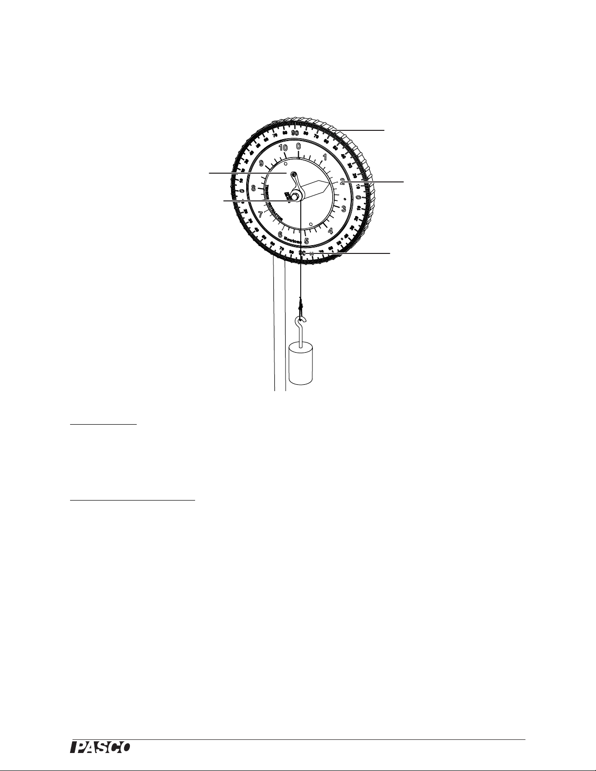
The string is secured
with a screw
The string is wrapped
around th e ce nt er pu lley
ME-6855
To zero the angle scal e,
rotate the outer ring
Force is indicated on the
inner scale, which is red to
match th e red po inter
Angle is indicated on the
outer scale
A mass can be hung from
the wire hook
Figure 1: Front view
Included Part s
• Tension Protractor
• String, 15 cm
• Wire hook
Other Parts Recommended
• 90 cm Steel Rod (PASCO part ME-8738)
• Large Table Clamp (ME-9472)
• Additional string (SE-8050)
• Hooked Mass Set (SE-8759)
Introduction
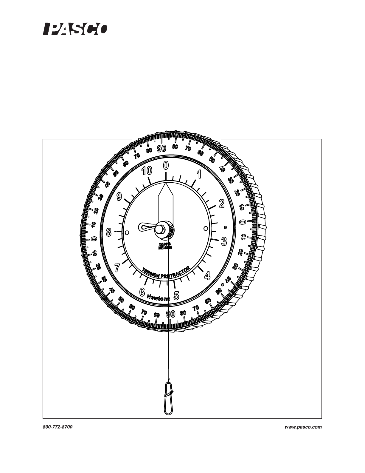
The Tension Protractor is used to measure s tring tension and angle si mu ltaneously. It eliminates the need for separate
spring scales and protractors in equilibrium experiments.
About the Apparatus
The Tension Protractor consists of a torsion spring scale and a protractor.
The string is attac hed to the rotating part of the protractor and wrapp ed twice around a small pulley (see Figure 1).
When the string is pulled, the torsion spring stretches and the red point er rotates. The string tension is read on the
®
1
Page 4
Tension Protrac tor Set-up
inner red scale as indicated by the red pointer. The force scale measures from 0.0 N to
10.0 N in 0.1 increm en ts. The force measu r ement is accurate to ±4% of the reading.
The string can be pull ed at any angle in the plane of the prot ractor. The strin g angle i s read
where the strin g cr o sses the outer degree scale. The ang le scal e is marked from 0° to 90°
in each of four quadrants. Horizontal (to the left or right) is 0° and vertical (stra ight up or
straight do wn) is 90 °. Note tha t the a ngle marki ngs a re sli ght ly offs et i n orde r to ali gn with
the string, which doe s not originate from the center of the circle but rather from a point
tange n t to th e p ulley.
Set-up
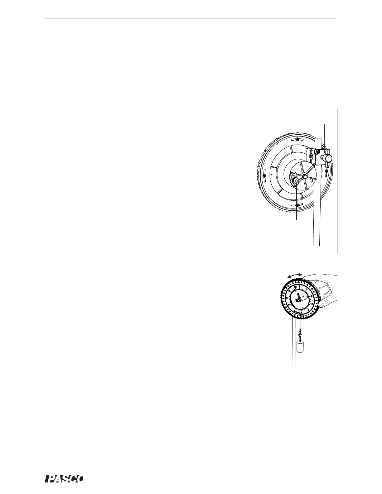
Mounting the Tension Protracto r on a Rod
Mount the Tension Protractor on a horizonta l or a vertical rod using the att ac hed
rod clamp as shown in Figure 2.
Zeroing the Force Scale:
After attaching the Tension Protractor to a rod, follow these steps to ensure that
the red pointe r ind i ca tes 0 N when n o f o rc e is applie d .
1. Allow the string to hang freely with no force applied.
2. Loosen the thumb scr ew on the back of the Tension Protractor (Fi gure 2).
3. Move the screw up or down to set the red pointer to zero on the face of the
Tension Protractor.
4. Tighten the thumb screw.
Zeroing the Angle Scale
After attaching the Tension Protractor to a rod, follow these steps to ensure that the string
crosses 90° when it is hanging vertica lly.
Clamp the protractor to a
vertical or hor i zon tal rod
To zero the
force scale,
loosen and
move the
thumbscrew
Figure 2: Back view
1. Hang a small mass on the string to act as a plumb bob (Figure 3).
2. Turn the outer ring or the protractor to rotate the angl e scale (it is held in place by fric-
tion). Align the 90° mark with the string.
Measuring Force and Angle
1. Ensure that the string is wrapped around the pulley twice so that the string is always
tangent to the pulley regardless of the string angle or tension.
2. Hang a mass from the wire hook (as in Figure 1), or set up an arra ngem ent of string,
masses and o ther obj ects to ap ply tensi on. See th e expe riments on t he foll owin g pages
for examples.
3. Read the magnitude of force on the inner red scale as indicated by the red pointer.
4. Read the angle on the outer s cale where the string crosses it.
®
Figure 3: Zero the
angle sc ale
2
Page 5

Tension Protract or String Replacement
String Repl acement
The Tension Protractor is designed for use with Braided Physics String (PASCO part
SE-8050). Usin g stri ng of a di f ferent dia meter wil l caus e err or in the forc e read ing. Fol low
these steps to replace the string.
1. Use a #0 or #1 phillips screwd river to remove the screw on the face of the Tension
Protractor.
2. Remove the old stri ng.
3. Tie a loo p at the end of the new string.
4. Put the screw through the loop and replace the screw in the face of the protra ctor.
5. Wr ap the string twice around the pulley in the c lockwise direction.
6. Tie the wire clip to the end of the new string. If the wire clip is lost, it can be replaced
with a small paper clip.
About the Experiments
The experiment s in this ma nual use one or two Tension Protractors and other equipment,
such as rods, clamps , and masses that are commonly f ound in introductory labs.
1. Static Equilibrium with Unequal Angle s (page 4): Examine the forces required
to hang a weight in s tatic equilibrium using two strings at different a ngles.
2. Boom in Static Equilibrium (page 7): Examine the two require ments for a boom
in equilibrium . The boom is pivoted at one end and a string suspends the oth er end.
3
®
Page 6

Tension P rotractor Experiment 1: Static Equilibriu m with Unequal An gles
Experiment 1: Static Equilibrium with Unequal Angles
Equipme nt N ee ded
Suggested Part
• (2) Tension Protractors ME-6855
• (2) Large Table Clamps ME-9472
• (3) 90 cm Steel Rods ME-8738
• (2) Multi Clamps SE-9442
• Hooked Mass Set SE-8759
• Braided Physics String SE-8050
• Balance SE-8723
Purpose
The purpose of this experiment is to verify that the vector
sum of the forces acting on an ob ject in equilibrium is zero.
Pre-lab Question
If an object is suspended by two strings at two different
angles, as shown in Figure 1.1, which string will have the
greater te nsion?
Theory
The vector sum of the forces acting on an object in equilibrium is zero:
String #1
String #2
Figure 1.1
(eq. 1-1)
∑
F
0=
i
i
This requires that the sum of the force componen ts in the x- and y-dir ections must each
separately be zero:
(eq. 1-2)
(eq. 1-3)
∑
∑
F
i
i
0=
ix
F
0=
iy
For example, if three forces are acting on an object (as s hown in Figure 1.2), Equatio n 1-2
yields
(eq. 1-4)
(eq. 1-5)
F
cos F
2
F
–0=
2xF1x
θ
2
θ
cos–0=
1
1
This can also be inte rpreted as requir ing the magnit udes of the x-compon ents of the force s
to be equal and opposite:
(eq. 1-6)
F
2x
F1x=
F
F
1x
2y
1
F
1y
θ
θ
1
F
F
2
2
F
2x
(eq. 1-7)
4
F
θ
cos F
2
θ
2
cos=
1
1
F
F3y=
3
Figure 1.2
®
Page 7

Tension P rotractor Experimen t 1: Static Equil ibrium with Unequ al Angles
Similarly, Equation 1- 3 y ields
(eq. 1-8)
(eq. 1-9)
F
1yF2yF3y
sin F
F
1θ1
–+0=
sin F3–+0=
2θ2
Or, the sum of the magnitudes of the forces up must equal the sum of the magnitudes of
the forces down:
+ F3y=
(eq. 1-10)
(eq. 1-11)
F
sin F
F
1θ1
1yF2y
sin+ F3=
2θ2
Procedure
1. Clamp two rods (90 cm long) vertically to the table, approximately 80 cm apart.
Attach two Tension Protractors (oriented with zero degrees horizontal) to a cross rod,
and clamp this rod between the vertical rods as shown in the Figure 1.3 (but don’t
attach th e ma ss ye t ).
Figure 1.3: Set-up
2. Zero the force scale of each Tension Protract or: Without anything a ttached to the Ten-
sion Protractor st ring, adjust the thumb screw in the back until the force scale reads
zero.
3. Zero the angle scale of each Tension Protractor: Hang a small ma ss (10 g) from the
hook. Rotate the outer ring to align the 90° ma rk with the string (Figure 1.4).
4. Cut a string a bout 60 cm long. Tie a loop about 25 cm from one end so that the s tring
length on one side of the loo p is about 20 cm and the st ring lengt h on the other side of
the loop is 35 cm. Tie one end of the strin g to the wire hook on one of the Tension
Protractor s and tie the other end of the string to the wire hook of the other Tension
Protractor. Hang a 500 g mass from the string loop (Figure 1.3).
5. Read the magnitude of force an d the angle for eac h string and record them in
Table 1.1.
®
Figure 1.4: Zero the
angle sc ale
5
Page 8

Tension P rotractor Experiment 1: Static Equilibriu m with Unequal An gles
6. Remove the hooked mass and use a balance to find it s ex act mass. Record it in
Table 1.1.
Table 1.1: Data
Magnitude of Force (N ) Angle (°) Hanging Mass (kg)
Tension 1
Tension 2
Analysis
1. Calculate the weight of the hanging mass and record it in Table 1.2.
2. Calculate the x- and y-component s of the tension of each str ing. Record them in
Table 1.2.
Table 1.2: Calculations
Weight of Hanging Mass
x-component of Tension 1
x-component of Tension 2
y-component of Tension 1
y-component of Tension 2
3. Calculate the sum of the forces to the left and the sum of forces to the right. Calculate
the per cent difference between them. Record these values in Tab le1.3.
4. Calculate the sum of the upward forces and the sum of the downward forces. Calcu-
late the percent difference between them. Record these values in Table 1.3.
Table 1.3: Results
Left
Sum of x-components
Right
Upward
Sum of y-components
Downward
5. Estimate th e pre cision of the tension and angle measurements. Are the res ulting
forces being compared the same within the range of the precision?
Percent Difference
6
®
Page 9

Tension P rotractor Experiment 2: Boom in Stat ic Equilibrium
Experiment 2: Boom in Static Equilibrium
Equipme nt N ee ded
• Tension Protractor ME-6855
• Large Table Clamp ME-9472
• Multi Clamp SE-9442
• Hooked Mass Set SE-87 59
• Braided Physics String SE-8050
•Level SE-8729
• (2) 90 cm Steel Rods ME-8738
• Balance SE-8723
• Meter Stick with a hole in each end
(requires drilling 8 mm or 5/16 inch
holes)
• short rod, about 6 mm (1/4 inch) in
diameter and 15 cm (6 inches) long
Suggested Part
SE-8729
Purpose
The purpose of this experiment is to examine the two requ irements for a boom to be in
equilibrium and us e them to determine the forces acting on the boom at the pivot .
Pre-lab Questions
1. What are the two requiremen ts for an ext ended object to be in equilib rium?
2. Does the tensio n of the string shown in Figure 2.1 cause a clockwise or counterclock-
wise torque about the pivot?
3. Does the hanging mass shown in Figure 2.1 cause a clockwise or counterclockwise
torque about the pivot point?
4. Where does the weight of the boom (in this case, the meter sti ck) a ct?
5. Which angle will you meas ure with the Tension Protractor (in Figure 2.1)?
Theory
There are two requirements for an object in equil ibrium:
1. The vector sum of the forces acting on the object in equilibrium is zero:
∑
∑
F
0=
i
i
τ
0=
i
i
(eq. 2-1)
2. The vector sum of the torque s acting on the object in equilibrium is zero:
(eq. 2-2)
Counterclockwise torques are de fined to be positive and cloc kwise torques are negat ive.
Torque is calculated using , where r is the lever arm distance measured
from the pivo t to the point where the force (F) is applie d, and θ is the angle between the
lever arm (r) and the applied force (F).
7
τ r θsin()F=
®
Page 10

Tension P rotractor Experiment 2: Boom in Stat ic Equilibrium
Requir ement #1 also implie s that the sum of the force componen ts in the x- and
y-directions must each separately be zero:
(eq. 2-3)
(eq. 2-4)
∑
∑
F
i
i
0=
ix
F
0=
iy
Another way of stating Requirement #2 is that t he sum of all the c lockwise torques equals
the sum of all the counterclockwise torques:
(eq. 2-5)
∑
τ
clockwise
∑
=
τ
counterclockwise
Procedure
1. Measure the masses of the meter stick and a hooked mass (use th e mas s marke d
500 g). Record these masses in Table 2.1.
2. Balance t he meter stick on a sharp edge, such a s the edge of a table, to find the ce nter
of mass of the meter stick. Record the position of the center of mass in Table 2.1. T his
is the point at which it is assumed that the total weight of the meter stick acts.
3. Clamp one of the long rods (90 cm lo ng) vertically to the table (see Figure 2.1).
Attach a right-a ngle clamp to the rod near the table. Clamp the short rod to the vertical rod to act as a pivot.
4. Slide the hole at one end of the meter stick over the short rod. The meter stick should
pivot freely on the rod.
Tension Prot ractor
string
right- angle clamp
meter stick
short rod acting
as pivot poi nt
hooke d mass
Figure 2.1: Set-up
5. Tie a loo p o f string loosely around the meter stick. This will be used to hang the
hooked mass.
®
8
Page 11

Tension P rotractor Experiment 2: Boom in Stat ic Equilibrium
6. Clamp the Tension Protractor near the top of the vertical rod.
7. Zero the force scale of the Tension Protractor: Without anything attached to the Ten-
sion Protractor st ring, adjust the thumb screw in the back until the force scale reads
zero.
8. Zero the angle scale of the Tension Protractor: Ha ng a small mass (10 g) from the
hook. Rotate the outer ring to align the 90° ma rk with the string (Figure 2.2).
9. Tie a string to the hook of the Tension Protractor . Use a piece of string that is long
enough to reach the free end of the meter stick with the stick being approximately
horizontal. Tie the other end of the string to the end of the mete r sti ck, keeping the
meter stic k approx imat ely hori zonta l. Keep t he mete r sti ck and th e face of the Tension
Protractor in the same plane, and keep the pivot rod perpendicular to that plane.
10. Hang the 500 g mass from the loop of string arou nd the meter s tick a t about t he 60 cm
mark.
11. Use the level to determ ine if the meter stick is horizontal. Make the stick level (horizontal) by changing th e height of the pivot clamp or the height of th e Tension Protractor. Or, for s mall adjustments, move the hangi ng mass, but keep it be tween the 55 cm
Figure 2.2: Zero the
angle sc ale
and 65 cm marks.
12. Record the angl e of the string in Table 2.1.
13. Record the tension in the string in Table 2.1.
14. Record the distance from the pivot to the point where the stri ng is attached to the
meter stick in Table 2.1.
15. Record the distance from the pivot to the hanging mass in Table 2.1.
16. Record the distance from the pivot to the center of mass of the meter stick in
Table 2.1.
Table 2.1: Data
Mass of meter stick
Mass of hooked mass
Center of mass of meter stick
Angle of string
Tension
Distance from pivot to string
Distance from pivot to hanging mass
Distance from pivot to center of mass of meter stick
Analysis
1. Calculate the clockwise torques about the pivot caused by the hanging mass and the
stick and record them in Table 2.2. Calculat e the total clockwise torque and record it
in Table 2.2.
2. Calculate the counterclockwise torque about the pivot caused by the tension in the
string and record it in Table 2.2. (Don’t forget to account for the ang le!) Calculate the
total cou nterclockwise torque and record it in Table 2.2.
9
®
Page 12

Tension P rotractor Experiment 2: Boom in Stat ic Equilibrium
3. Compare the total clockwise torque to the total counterclockwise torque by calculating the pe r cent difference. Record the perc en t difference in Table 2.2. Are they the
same? Should they be the same?
Table 2.2: Calculations and Results
Torque caused by hang ing wei ght
Torque ca u s ed by met e r st ick
T otal clockwise torque
Torque ca u s ed by st rin g
T otal counterclockwise torque
Percent difference
4. Calculate the known horizontal forces. Use Equation 2-3 to de termine the unknown
horizontal forc e at the pivot and record it in Table 2.3.
5. Calculate the known vertical f orces. Use Equation 2-4 to det erm ine the unknown vertical fo rc e at th e pi v o t an d re co r d it in Table 2.3 .
6. Calculate the magnitude and dire ction of the force at the pivot. Specify whether you
are measuring the angle from the horizontal or the vertical. Draw a diagram showing
the angle of the force. Record the magnitude and angle in Table 2.3.
T able 2.3: Forces at the Pivot
Horizontal pivot force
Vertical pivot force
Magnitude of pivot force
Angle of pivot force
Questions
1. How do the clockwise tor q ues compare to the counterclockwise torques?
2. Is the direction of the pivot force parallel to the meter stick?
3. Using the convention that counterclockwise torques are positive and clockwise
torques are negat ive, sum the torques about the center of mass of the meter sti ck.
What do you expect the sum to be?
®
10
Page 13

Tension P rotractor Additional Exp eriment Sugg estion: Hanging a L evel Sign
Auth
Additional Experiment Suggestion: Hanging a Level Sign
Using a set-up similar to that of Experiment 1, hang a rectangular sign board from two different-leng th s trings. Attach the strings to the sign as shown. Adjust the posi tions of the
Tension Protractors to make the sign is le vel. Confirm that the two requirements for equilibrium are satisfied. Predict what would happen if the two unequal length strings were
attached to the uppe r corners of the sign.
Technical Support
For assistance with any PASCO product, contact PASCO at:
Address: PASCO scientific
10101 Foothills Blvd.
Roseville , CA 95747-7100
Phone: 916-786-3800 (worldwide)
800-772-8700 (U. S.)
Fax: (916) 786-7565
Web: www. pasco.com
Email: support@pasco.com
For more information ab out the Tension Protrac tor and the latest revision of this Instruction Manual, vi sit:
www.pasco.com/go?ME-6855
Limited Warranty For a description of the product warranty, see the PASCO catalog. Copyright
The PASCO scientific 012-10381A
reserved. Permission is granted to non-profit educational institutions for reproduction of any part of this
manual, providing the reproductions are used only in their laboratories and classrooms, and are not
sold for profit. Reproduction under any other circumstances, without the written consent of PASCO scientific, is prohibited. Trademarks PASCO and PASCO scientific are trademarks or registered
trademarks of PASCO scientific, in the United States and/or in other countries. All othe r brands , products, or service names are or may be trademarks or service marks of, and are used to identify, products or services of, their respective owners. For more information visit www.pasco.com/legal.
Tension Prot ractor Instruction Manual
is copyrighted w ith all rights
or: Ann Hanks
11
®
 Loading...