

Page 1

®
Parallel Spring Bracket
ME-6844
Instruction Sheet
012-09843A
Included Equipment Part Number
Suspension Bracket
ME-6844
Parallel Hook Bar
Thumbscrews (2 pieces) 617-016
Additional Equipment Recommended
Series/Parallel Spring Set ME-6842
Equal Length Spring Set ME-8970
Hooked Mass Set SE-8759
Large Table Clamp ME-9472
45 cm Rod ME-8736
Meter Stick SE-8695
800-772-8700 www.pasco.com
Introduction
The Parallel Spring Bracket allows springs to be combined in
series and parallel. Masses can be hung in offset positions to
compensate for springs of different strengths.
The Parallel Spring Bracket is ideal for:
• exploring how spring constants add when springs are
arranged in series or in parallel,
• demonstrating the analogy between combinations of springs
and combinations of capacitors, and
• exploring torque acting on the hook bar by placement of the
mass and springs at different positions.
Page 2
Parallel Spring Bracket ME-6844
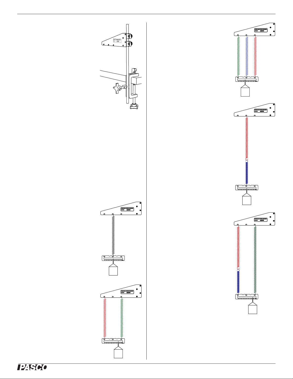
Set-up
1. Assemble the suspension bracket, a
large table clamp and a rod as illustrated. The table clamp (rather than a
base) and a relatively short rod are
recommended for maximum stability.
2. Hang any combination of springs
from the suspension bracket.
3. Attach the parallel hook bar to the
bottom of the spring combination.
4. Hook a mass onto the notched slot of
the parallel hook bar. The mass should be large enough to
stretch all springs at least slightly.
5. Move the mass left or right along the notched slot to find the
position that makes the hook bar as close to horizontal as
possible.
6. Check that all springs are stretched. You should be able to
see between the coils of every spring. If one of the springs is
not stretched, increase the hanging mass.
Three Parallel
Three different springs (40 N/m, 20 N/m,
and 10 N/m) from the Series/Parallel
Spring Set are combined in parallel.
Series
Two springs are linked end-to-end to
form a series combination.
Sample Configurations
Single Spring
Though the hook bar is not necessary to
attach a mass to a single spring, it does
provide a convenient point from which to
measure changing displacement.
Two Parallel
Two springs (10 N/m and 40 N/m) from
the Series/Parallel Spring Set (ME-6842)
are combined in parallel. The hanging
mass is placed off center to make the
hook bar level.
Series and parallel
Two short springs from the Series/Parallel Spring Set are linked in series. That
combination is in parallel with a single
long spring from the Equal Length Spring
Set (ME-8970). When not stretched, the
long spring is twice the length of each of
the short springs.
®
2
Page 3

Parallel Spring Bracket ME-6844
Parallel Springs of Different Length
A long spring
from the Equal
Length Spring Set
and a short spring
from the
Series/Parallel
Spring Set are
combined in parallel. Both springs have
the same spring constant
(40 N/m). The initial mass
is placed off-center to make
the hook bar level; however
addition mass is added to the
center to stretch both springs
equally.
When the system oscillates, the hook
bar rocks. However, if the mass is hung
from the center (so that the hook bar is not
level) it oscillates without rocking.
A similar effect can be achieved using two identical springs with
one vertically offset using string.
3. Measure the distance from the floor to the bottom of the
hook bar again.
4. Calculate the change in force (the weight of the additional
mass), ∆F.
5. Calculate the change in position of the hook bar, ∆x.
6. Calculate the resultant spring constant using
(eq. 1)
∆F
k
-------=
∆x
The above equation lacks the negative sign usually found in
expressions of Hooke’s Law because F in this case is the applied
force rather than the force exerted by the springs.
For better precision, increase the hanging mass incrementally and
make a graph of ∆F versus ∆x. The slope of the best-fit line is k.
Addition of Spring Constants
The combination of springs is analogous to the combination of
capacitors. The equivalent spring constant of two or more springs
in parallel is
Modified Series
With this combination of springs, string, and pulleys, the balance point of the hanging mass is
always at the center of the hook bar regardless of
the spring constants or lengths.
Measurements and Calculations
Spring Constant
Use the following method to measure the spring constant of a
spring or combination of springs.
1. With the initial mass hanging from the hook bar (so that all
springs are slightly stretched), measure the distance from the
floor to the bottom of the hook bar.
2. Add some mass (typically about 500 g) to the hanging mass.
(eq. 2)
k
k1k2k3…+++=
eq
combination
For springs in series, the equivalent spring constant is
1
1
(eq. 3)
1
-------
k
-----
k
eq
1
-----
k
1
----- …+++=
k
2
3
combination
Force and Torque
The objects
attached to the
hook bar (springs
and hanging
mass) each exerts
a torque and a
force on it. When
the system is
static, the net
torque and net
force are both
zero.
When the hook
bar has two
springs and one
mass attached to
it, it is possible to
determine the
three separate
forces:
F
mg
s1
r
s2
r
m
parallel
series
F
s2
®
3
Page 4

Parallel Spring Bracket ME-6844
(eq. 4)
F
Fs1Fs2mg–+0==
net
The axis about which the torques are measured is chosen to be at
the “0 cm” mark. Spring #1 is attached at the axis, therefore its
torque is zero. The net torque is
(eq. 5)
Solving for F
(eq. 6)
τ
netrs2Fs2rm
yields:
s2
mg–0==
r
m
------
F
s2
mg=
r
s2
Combining equations 4 and 6 gives us:
r
m
1
------–
(eq. 7)
F
s1
mg=
r
s2
Period of Oscillation
The period of oscillation of a mass on a spring (or combination of
springs) is
T 2π
The mass, m , should include the hanging mass, the mass of the
hook bar, and 1/3 of the mass of the springs.
m
----=
k
Storage
To keep the bracket and hook bar together when not in use, clamp
the hook bar under the thumbscrews as illustrated.
Technical Support
For assistance with any PASCO product, contact PASCO at:
Address: PASCO scientific
10101 Foothills Blvd.
Roseville, CA 95747-7100
Phone: 916-786-3800 (worldwide)
800-772-8700 (U.S.)
Fax: (916) 786-7565
Web: www.pasco.com
Email: support@pasco.com
To demonstrate this relationship for any combination of springs,
use a stop watch to measure the period of oscillation. Increase the
hanging mass in steps. Make a graph of T
of the best-fit line is 4π
2
/k.
2
versus ∆m. The slope
Sensor-based Measurement
To measure the spring
constant using a rotary
motion sensor (RMS)
and a force sensor, set
up the equipment as
illustrated. Pull the
force sensor to stretch
the spring combination.
Make a graph of force
(measured by the force
sensor) versus linear
position (measured by
the RMS). The slope of
the best-fit line is the
spring constant.
Limited Warranty For a description of the product warranty, see the
PASCO catalog.
Copyright The PASCO scientific 012-09843A
Instruction Sheet
granted to non-profit educational institutions for reproduction of any part of
this manual, providing the reproductions are used only in their laboratories
and classrooms, and are not sold for profit. Reproduction under any other
circumstances, without the written consent of PASCO scientific, is prohibited.
Trademarks PASCO, PASCO scientific, DataStudio, PASPORT, and
Xplorer GLX are trademarks or registered trademarks of PASCO scientific,
in the United States and/or in other countries. All other brands, products,
or service names are or may be trademarks or service marks of, and are
used to identify, products or services of, their respective owners. For more
information visit www.pasco.com/legal.
is copyrighted with all rights reser ved. Permission is
Parallel Spring Bracket
®
4
 Loading...