

Page 1

®
Instruction Manual
Projectile
Launcher
Base
Ballistic Pendulum
Vertical upright
Trigger String
Included: Ramrod, 2-D Collision Accessory,
Steel Balls (2), Plastic Balls (3)
Not shown: Safety Glasses (2 pair)
Angle indicator
Ballistic Pendulum/
Projectile Launcher
ME-6830, ME-6831
012-05375C
*012-05375*
Page 2

®
The cover page shows the PASCO Ballistic Pendulum with the Short Range Projectile Launcher mounted on the
vertical part of the base. The Ballistic Pendulum is designed for traditional ballistic pendulum exp eriments and
can also be used for projectile motion experiments and demonstrations. When the Projectile Launcher is used for
projectile motion experiments, the launch angle at the upper launch position can vary from 0 to 90 degrees, and
the firing height is fixed for any launch angle. The Launcher can also mounted in a horizontal position that is
height-adjustable. The vertical base of the Ballistic Pendulum also has a dedicated position for the Launcher fo r
Ballistic Pendulum experiments. This manual contains copy-ready experiments and demonstrations for the ballistic pendulum and projectile launcher.
ii
Page 3

®
Table of Contents
Equipment . . . . . . . . . . . . . . . . . . . . . . . . . . . . . . . . . . . . . . . . . . . . . . . . . . . . . . . . . . . .1
Assembly . . . . . . . . . . . . . . . . . . . . . . . . . . . . . . . . . . . . . . . . . . . . . . . . . . . . . . . . . . . . .2
Introduction . . . . . . . . . . . . . . . . . . . . . . . . . . . . . . . . . . . . . . . . . . . . . . . . . . . . . . . . . . . 2
General Operation of the Projectile Launcher . . . . . . . . . . . . . . . . . . . . . . . . . . . . . . . . . 4
Ballistic Pendulum Theory . . . . . . . . . . . . . . . . . . . . . . . . . . . . . . . . . . . . . . . . . . . . . . . . 6
Installation of the Optional Photogate Bracket. . . . . . . . . . . . . . . . . . . . . . . . . . . . . . . . . 8
Installation of the Two-Dimensional Collision Attachment. . . . . . . . . . . . . . . . . . . . . . . . 9
Expectations for the Projectile Launcher . . . . . . . . . . . . . . . . . . . . . . . . . . . . . . . . . . . . . 9
Expectations for the Ballistic Pendulum. . . . . . . . . . . . . . . . . . . . . . . . . . . . . . . . . . . . . . 9
EXPERIMENTS
1. Projectile Motion . . . . . . . . . . . . . . . . . . . . . . . . . . . . . . . . . . . . . . . . . . . . . . . . . . . . 11
2. Projectile Motion Using Photogates. . . . . . . . . . . . . . . . . . . . . . . . . . . . . . . . . . . . . . 15
3. Projectile Range versus Angle. . . . . . . . . . . . . . . . . . . . . . . . . . . . . . . . . . . . . . . . . . 19
4. Projectile Path . . . . . . . . . . . . . . . . . . . . . . . . . . . . . . . . . . . . . . . . . . . . . . . . . . . . . . 23
5. Conservation of Energy . . . . . . . . . . . . . . . . . . . . . . . . . . . . . . . . . . . . . . . . . . . . . . . 27
6. Conservation of Momentum. . . . . . . . . . . . . . . . . . . . . . . . . . . . . . . . . . . . . . . . . . . . 31
7. Vary Angle to Maximize Height . . . . . . . . . . . . . . . . . . . . . . . . . . . . . . . . . . . . . . . . . 35
8. Projectile Velocity—Approximate Method). . . . . . . . . . . . . . . . . . . . . . . . . . . . . . . . . 37
9. Projectile Velocity—Exact Method) . . . . . . . . . . . . . . . . . . . . . . . . . . . . . . . . . . . . . . 39
DEMONSTRATIONS
10. Do 30° and 60° Launch Angles give the Same Range? . . . . . . . . . . . . . . . . . . . . . 43
11. Simultaneously Fire Two Balls Horizontally at Different Speeds. . . . . . . . . . . . . . . 45
12. Shoot through Hoops. . . . . . . . . . . . . . . . . . . . . . . . . . . . . . . . . . . . . . . . . . . . . . . . 47
13. Elastic and Inelastic Collisions. . . . . . . . . . . . . . . . . . . . . . . . . . . . . . . . . . . . . . . . . 49
Teacher’s Guide. . . . . . . . . . . . . . . . . . . . . . . . . . . . . . . . . . . . . . . . . . . . . . . . . . . . . . . 51
Technical Support, Warranty, and Copyright. . . . . . . . . . . . . . . . . . . . . . . . . . . . . . . . . 57
iii
Page 4

®
Projectile Launcher
iv 012-05375C
Page 5

Ballistic Pendulum / Projectile Launcher
®
ME-6830, ME-6831
Equipment
The ME-6830 Ballistic Pendulum / Projectile Launcher includes the following:
Included Equipment Part Number
Ballistic Pendulum and Base (unassembled) 003-05374
Short Range Projectile Launcher Assembly 003-10550
Plastic Balls, 25 mm diameter (3) see ME-6802*
2-D (two-dimensional) Collision Accessory see ME-6802*
Ramrod see ME-6802*
Steel Balls, 25 mm diameter (2) 699-064
Safety Glasses (2 pair) 699-066
Trigger String (45 cm (18”)) 699-067
Hex Key 726-046
Required Equipment Part Number
C-Clamp, Large SE-7285
Recommended Equipment Part Number
Launcher Spares Kit* ME-6802
Time-of-Flight Accessory ME-6810
Projectile Catcher Accessory ME-6815
Photogate Mounting Bracket ME-6821A
Shoot-the-Target ME-6853
Photogate Head ME-9498A
Laser Sight Accessory OS-8527A
*The ME-6802 Launcher Spares Kit includes: Ramrod (2), Plastic Balls
(10-pack), 2-D Collision Accessory (2), Sights (5-pack), Plumb Bob
(24-pack), Nylon Thread (1 spool), and Thumbscrews (10).
The ME-6831 Ballistic Pendulum does not include the Short Range
Launcher. The ME-6831 Ballistic Pendulum includes two steel balls and
the hex key.
ME-6802 Launcher Spares Kit
1
Page 6
Ballistic Pendulum / Projectile Launcher Assembly
®
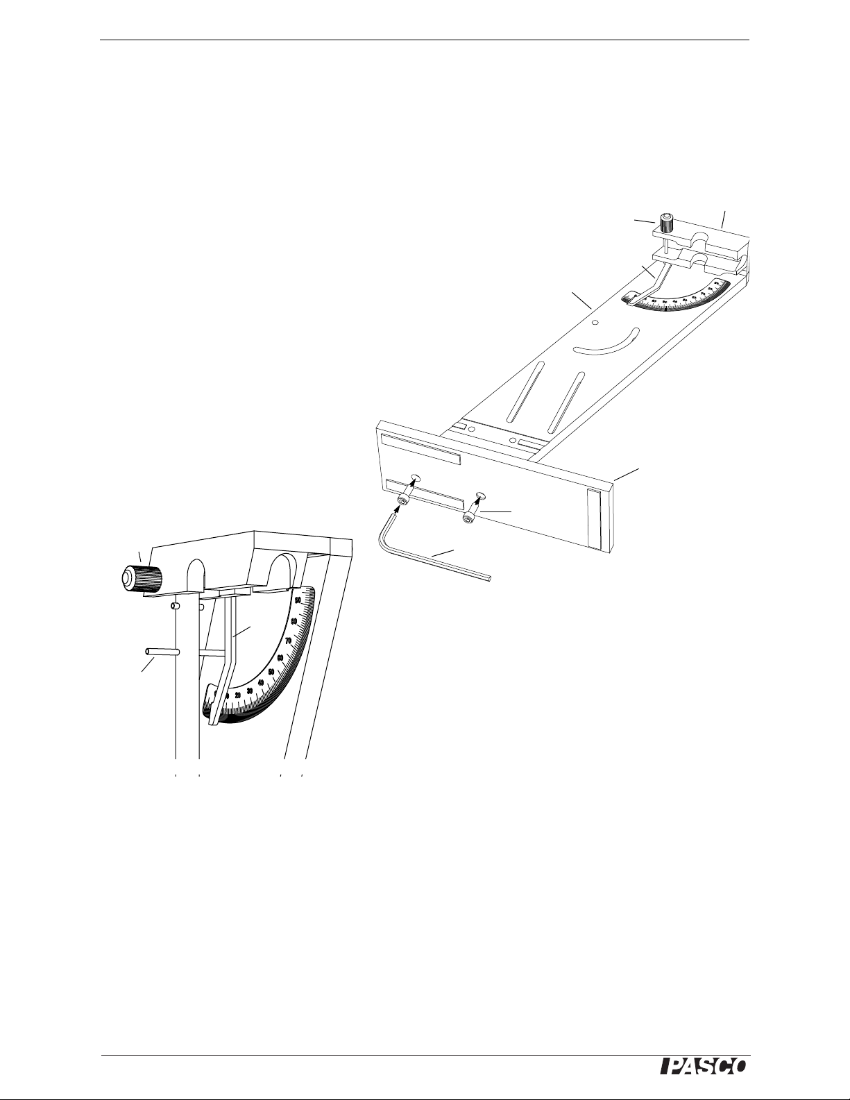
Upright
Base
Hex key
Socket head
screw
Axle
Angle Indicator
Assemble the Base
Angle
Indicator
Long pin
Axle
Mount the Ballistic Pendulum
Assembly
The Ballistic Pendulum / Projectile Launcher arrives in a custom-made package, and some assembly is required.
The package has several cut-outs for the Ballistic Pendulum and ramrod, base, upright and Projectile Launcher,
safety glasses, and miscellaneous small parts including a hex key (“Allen wrench”) used for assembly.
Assemble the Base
Unscrew the thumbscrew to temporarily
remove the Projectile Launcher from the
upright. Use the included hex key and the
two socket head screws to attach the base to
the upright. The screws are coated with a
strong adhesive that activates when they are
screwed into place.
Mount the Ballistic Pendulum
To attach the Ballistic Pendulum to the
upright, unscrew the axle from the yoke. The
Ballistic Pendulum has a hinge at the top of
the rod with a hole through it. Line up the
hole in the hinge with the axle hole in the
yoke, and screw the axle back into place.
Note that the long pin that extends from
either side of the Ballistic Pendulum rod
should be behind the angle indicator.
Yoke
Introduction
The PASCO Ballistic Pendulum / Projectile Launcher has been designed for ballistic pendulum and projectile
motion experiments and demonstrations. The only addition equipment required is a C-clamp for mounting the base
of the Ballistic Pendulum to a table or sturdy horizontal surface. The features of the Ballistic Pendulum include:
• Reliable Ball-Catcher Mechanism: The sensitive spring-loaded barb-type catch on the pendulum will catch
balls with a large range of speeds. In addition, the catcher holds the ball in line with the pendulum rod for best
accuracy.
• Removable Pendulum: All moving parts of the pendulum may be removed so that the mass and center of
mass can be measured accurately. In addition, the pendulum can be reversed so that elastic collisions can be
compared to inelastic collisions.
2
012-05375C
Page 7

®
Model No. ME-6830, ME-6831 Introduction
Wear Safety Glasses
• Variable-Mass Pendulum: The pendulum includes masses that can be removed so that the pendulum can be
used with lightweight balls over a wide range of speeds. Leave the masses on the pendulum when you use
heavyweight balls.
The features of the Projectile Launcher include:
• Launch at Any Angle: Balls can be launched from any angle from zero to ninety degrees measured from hor-
izontal (zero degrees). The angle is easily adjusted using thumbscrews and the built-in protractor and
plumb-bob give an accurate way to measure the angle of inclination.
• Three Range Settings: Each version of Projectile Launchers has three range settings. The Short Range Pro-
jectile Launcher ranges are approximately 1.2 m, 3 m, and 5 m when the launch angle is 45°. (The Long
Range Projectile Launcher ranges are approximately 2.5 m, 5 m, and 8 m. The Long Range Launcher has a
stronger spring and is useful for large classroom demonstrations.)
• Fixed Elevation Independent of Launch Angle: The Projectile Launcher can pivot at the muzzle end so the
elevation of the ball as it leaves the barrel does not change as the angle is varied. The upright part of the Ballistic Pendulum base has three positions for mounting the Launcher. At the top is a hole and curved slot for
use when you want to change the launch angle. The vertical slots let you mount the Launcher horizontall y at
different heights so you can fire a ball into targets such as a ball catcher on a PASCO Cart on a track. At the
bottom are two holes for use when you want to fire a ball horizontally into the Ballistic Pendulum.
• Repeatable Results: The piston keeps the ball from rubbing on the inside of the barrel as it travels so there is
no spin on the ball as it launches. When the base is secured to a table with a C-clamp, there is very little recoil.
The trigger is pulled with a string to minimize jerking.
• Barrel Sights and Safety Precautions: There are sites built-in to the barrel for
aiming the Projectile Launcher. View the sites by looking through the back end
of the barrel. WARNING: Never look down the front of the barrel because it
may be loaded. Safety glasses are provided, so use them. Look for the yellow
indicator through any of the five slots on the top of the barrel because the yellow indicator shows the position of the piston. If the indicator is between the
first and second slots (relative to the muzzle end), the piston is not cocked.
• Computer Compatible: One or two photogates can be attached to the Projec-
tile Launcher using the ME-6821A Photogate Mounting Bracket. When used
with a PASCO interface and data acquisition software, the photogates can measure the muzzle speed of the ball. Use a photogate and the ME-6810 Time of Flight Accessory to measure the
time of flight of the ball
• Compact Storage: When the barrel of the Launcher is aligned vertically with the base, the Launcher takes up
minimal space. The included ramrod and the Ballistic Pendulum base have hook-and-pile material that allows
the ramrod to be stored on the base.
012-05375C 3
Page 8

Ballistic Pendulum / Projectile Launcher General Operation of the Projectile La uncher
®
Trigger
String
Trigger
Protractor
Plumb Bob
Muzzle
Thumbscrews
Range
setting slots
(1 of 5)
Launcher Parts
Label details
Yellow Band in Wi ndow
Indicates Range
Launcher
on high
position
General Operation of the Projectile Launcher
Parts
Ready
• Attach the included Trigger String to the hole
in the Trigger . (For example, loop the string
through the hole and tie the ends together.)
• Always wear safety goggles when you are in a
room where a Projectile Launcher is being
used.
• Firmly clamp the base of the Ballistic Pendulum to a sturdy table or other surface.
• Mount the Projectile Launcher on the Ballistic
Pendulum base. Mount the Launcher to the
lower two holes in the base if you intend to
shoot horizontally at the ball catcher of the
Ballistic Pendulum.
• Use the hole and curved slot near the top of the
base when you want to adjust the Launcher’s
launch angle. Note: For this configuration, the
Launcher should be mounted on the ‘back
side’ of the Ballistic Pendulum base.
4
012-05375C
Page 9

®
Model No. ME-6830, ME-6831 Genera l Operation of the Projectile Launcher
Bore Sights
Front
site
Rear
site
Launcher
Aim
• If you have the Launcher mounted on the top position, you can adjust the angle of inclination above the horizontal by loosening the two thumbscrews and rotating the Launcher barrel to the desired angle. Use the plumb
bob and the protractor on the label to select the angle. Tighten both thumbscrews when the angle is set.
• You can ‘bore-sight’ through the barrel at a target, such as the ME-6853 Shoot-The
Target. Look through the back end of the barrel when the Launcher is not loaded.
There are two ‘tripod’ (three-spoke) sights inside the barrel, one at the end of the
barrel and one at the end of the piston (about midway in the barrel). Each sight has a
sighting hole at its center. Loosen the thumbscrews and C-clamp and adjust the
angle and position of the Launcher to align the centers of both sights on your target.
Tighten the thumbscrews and C-clamp when the Launcher is aimed.
Load
• T o load a ball in the Launcher when its mounted on the low position, either hold the
Ballistic Pendulum out of the way or rotate the pendulum until the rod is horizontal
and it catches in the component clip on the underside of the yoke.
• Place a ball in the muzzle of the Launcher. NOTE: Always cock the piston with a ball in the piston. You may
damage the piston if you use the ramrod without a ball in the piston.
• Remove the ramrod from its storage place on the edge of the upright. While looking through the range-setting
slots on the top side of the Launcher, push the ball down the barrel with the ramrod until the trigger catches
the edge of the piston at the desired range setting. (The trigger will “click” into place.)
• When the yellow indicator tape on the piston is visible in the middle range-setting slot, the piston is in the SHORT RANGE position.
When the indicator tape on the piston is visible in the next
range-setting slot (fourth from the muzzle), the piston is in the
MEDIUM RANGE position, and when the tape is visible in the last
range-setting slot, the piston is in the LONG RANGE position.
• Remove the ramrod and return it to the storage place on the edge of the upright.
• When the Projectile Launcher is loaded, the yellow indicator tape is visible through one of the range-setting
slots on the upper side of the barrel. Never look down the barrel! To check whether the Launcher is loaded,
look through the range-setting slots on the barrel.
Shoot
• Before shooting the ball, make certain that no one is in the way.
• T o shoot the ball, pull straight up on the trigger string that is attached to the trigger. You only need to pull about one centimeter.
• The trigger will automatically return to its initial position after you release the
string.
Maintenance and Storage
• The Ballistic Pendulum/Projectile Launcher does not need any special maintenance. Do not oil the Launcher!
• To store the Launcher in the least amount of space, align the barrel vertically.
One way is to mount it in one of the two vertical slots. Tighten the thumbscrews
to hold the Launcher in place.
012-05375C 5
Page 10

Ballistic Pendulum / Projectile Launcher Ballistic Pendulum Theory
®
PE Mgh
cm
=
hR1 cos–=
PE MgR
cm
1 cos–=
KE
1
2
-- -
Mv
p
2
=
P
p
Mv
p
=
KE
P
p
2
2M
------- -
=
P
p
2MKE=
Ballistic Pendulum Theory
Overview
The ballistic pendulum is a classic method of determining the velocity of a projectile. It is also a good demonstration of many of the basic principles of physics.
The ball is fired into the ballistic pendulum, which then swings up a measured amount. From the height reached by
the pendulum, you can calculate its gravitational potential energy. The gravitational potential energy is equal to the
kinetic energy of the pendulum at the bottom of the swing, just after the collision with the ball.
You cannot equate the kin etic energy of the pendulum after the collision with the kinetic energy of the ball before
the swing since the collision between ball and pendulum is inelastic, and kinetic energy is not conversed in inelastic collisions. Momentum is conserved in all forms of collisions, so you know that the momentum of the ball
before the collision is equal to the momentum of the pendulum after the collision. Once you know the momentum
of the ball and the ball’s mass, you can determine the initial velocity.
There are two ways of calculating the velocity of the ball. The first method (called the “approximate method”)
assumes that the pendulum and the ball together act as a point mass located at their combined center of mass. This
method does not take rotational inertia into account. It is somewhat quicker and easier than the second method
(called the “exact method”), but not as accurate.
The second method (exact method) uses the actual rotational inertia of the pendulum in the calculations. The equations are slightly more complicated, and it is necessary to take more data in order to find the moment of inertia of
the pendulum, but the results are generally better.
Please note that the subscript “cm” used in the following equations stands for “center of mass”.
Approximate Method
Begin with the potential energy of the pendulum at the top of its swing after the collision with the ball:
where M is the combined mass of the pendulum and ball, g is the acceleration due to gravity, and h is the change
in height. Substitute for the change in height:
where R
energy is equal to the kinetic energy immediately after the collision:
where v
the equation is:
is the distance from the pivot point to the center of mass of the pendulum/ball system. This potential
cm
is the speed of the speed of the pendulum just after collision. The momentum of the pendulum just after
p
which you can substitute into the previous equation to give:
Solving this equation for the pendulum momentum gives:
6
012-05375C
Page 11
®
Model No. ME-6830, ME-6831 Ballistic Pendulum Theory
P
b
mv
b
=
mv
b
2M2gRcm1 cos–=
R
cm
cm
cm
h
cm
m
v
Figure 1
v
b
M
m
---- -
2gR
cm
1 cos–=
PE MgRcm1 cos–=
KE
1
2
-- -
I
2
=
L
p
I=
KE
L
p
2
2I
--------
=
L
p
2IKE=
LpmR
b
2
mRbv==
-Mg sin
-Mg
Figure 2
mRbv 2IMgRcm1 cos–=
v
1
mR
b
----------
2IM gR
cm
1 cos–=
I=
This momentum equal to the momentum of the ball just before the collision:
Setting these two equations equal to each other and replacing KE with our known potential energy gives:
Solve this for the ball’s velocity and simplify to get:
Exact Method
The potential energy is found in a way identical to the way
shown previously:
For the kinetic energy, you can use the equation for angular
kinetic energy instead of linear kinetic energy, and substitute
into it the equation for angular momentum:
where I is the moment of inertia of the pendulum/ball combination, and is the angular velocity immediately after
the collision.
As you did previously, solve this last equation for angular momentum:
This angular momentum is equal to the angular momentum of the ball before the collision, as measured from the
pendulum pivot point:
where R
general equal to R
is the distance from the pendulum pivot to the ball. (NOTE: This radius is not in
b
, which is the distance from the pivot point to the center of mass for
cm
the pendulum/ball system.)
These two angular momenta are equal to each other, so:
Solve for v:
Now you need to find I, the moment of inertia of the pendulum and ball. To do this, start with the rotational equivalent of Newton’s Second Law:
where is torque, I is moment of inertia, and is angular acceleration. The force on the center of mass of the pendulum is Mg, and the component of force directed towards the center of the pendulum swing is F = -Mg sin
Figure 2.)
012-05375C 7
See
Page 12

Ballistic Pendulum / Projectile Launcher Ballistic Pendulum Theory
®
I RcmMg sin–=
MgR
cm
I
------------------
–=
k
m
--- -
x– 2x–==
2
MgR
cm
I
------------------
=
I
MgR
cm
2
------------------
MgR
cm
T
2
4
2
------------------------
==
Projectile
Launcher
barrel
Square
Nut
Thumb
screw
Photogate
Photogate
Photogate
Mounting
Bracket
T-slot
Thumb
screw
Install the Optional Photogate Bracket
The torque on the pendulum is thus:
For small angles, , sin so if you make this substitution and solve for you get:
This angular equation is in the same form as the equation for linear simple harmonic motion:
So if you compare the two equations, linear and angular, you can see that the pendulum exhibits simple harmonic
motion, and that the square of the angular frequency (
2
) for this motion is:
Solving for I gives the desired result:
where T is the period of the pendulum.
• NOTE: You used a small-angle approximation to find the equation for I, but I does not depend on . This
means that you must measure the period T using small angle oscillations. Once you have calculated I with that
period, you may use that value of I regardless of the amplitude reached during other parts of the experiment.
Installing the Optional Photogate Bracket (ME-6821A)
The Photogate Bracket is an optional accessory for mounting one or two photogates on the Projectile Launcher to
measure the muzzle speed of the ball.
• Prepare the Photogate Bracket by loosening the thumbscrew near the end of the bracket. Leave the square nut
in place on the end of the thumbscrew. Use the smaller (0.75 in) thumbscrews that are stored on the bottom
side of the bracket to mount one or two photogates to the bracket
• Align the square nut of the bracket with
the T-shaped slot on the bottom of the
Launcher barrel and slide the nut into the
slot until the photogate nearest to the barrel is as close to the muzzle as possible
without blocking the photogate beam.
Tighten the bracket thumbscrew to secure
the bracket in place.
8
012-05375C
Page 13

®
Model No. ME-6830, ME-6831 Ballistic Pendulum Theory
Plumb bob
Tie a triple knot
in the end.
Thread through
the hole.
Make the string
long enough.
Vertex
Repairing the Plumb Bob
50°
Projectile
Launcher
barrel
Square
Nut
T-slot
Thumbscrew
2-D Collision Accessory
Repairing the Plumb Bob
If the string breaks that holds the plumb bob on the protractor of the
Launcher, replace it with an equal length of nylon thread (such as the thread
included in the ME-6802 Launcher Spares Kit). Make sure that the replacement string is long enough so that when the Launcher is inclined at an angle
of 50°, the string extends well below the corner of the Launcher. Carefully
thread the replacement string through the small hole at the vertex of the protractor and tie a triple knot at that end of the string. To put the plumb bob
onto the string, thread the string through the hole in the center of the plumb
bob and tie a triple knot in that end of the string.
Installing the 2-D (two dimensional) Collision Accessory
Introduction
The 2-D (two dimensional) Collision Accessory is a plastic
bar with a thumbscrew and square nut. The bar has a post
and you can balance a second ball on the post in front of the
muzzle. When the launched ball collides with the second
ball, they experience a two dimensional (2-D) collision.
Assembly
To assemble the Collision Accessory, insert the thumbscrew through the hole in the plastic bar and screw the
square nut onto the thumbscrew. Leave the square nut loose
on the thumbscrew until you install the Collision Accessory onto the Launcher.
To install the Collision Accessory onto the Launcher, slide
the square nut into the T-shaped slot on the bottom side of the barrel. Adjust the position of the Collision Accessory and then tighten the thumbscrew. Place a ball on the top of the post, loosen the thumbscrew slightly, and
rotate the Collision Accessory to one side or the other until the ball on the post is in a place where it will be hit by
the launched ball at the angle that you want.
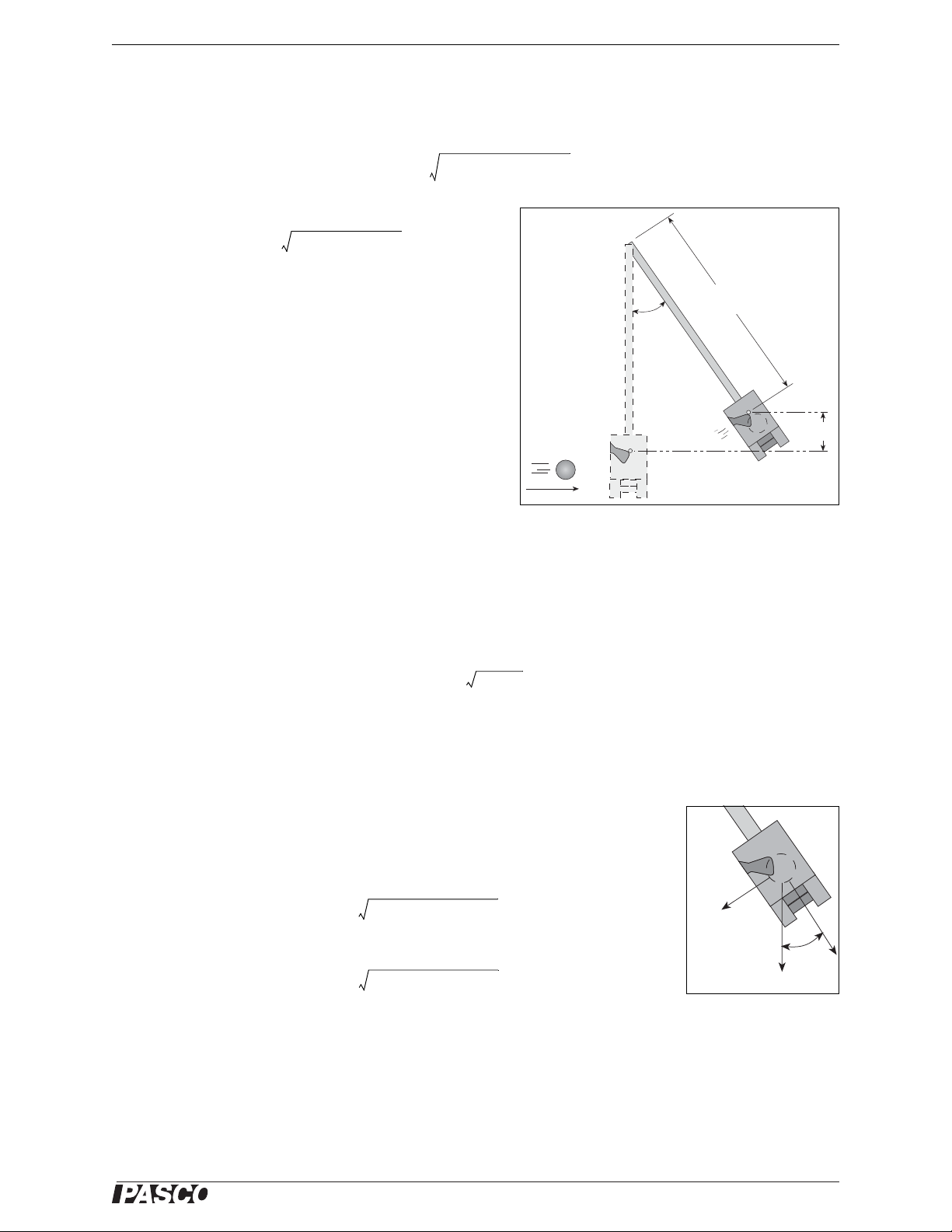
Expectations for the Projectile Launcher
• The muzzle speed will vary slightly with angle. The difference between muzzle speed when shot horizontally
versus vertically can be between zero to eight percent, depending on the range setting.
• Although the muzzle end of the Projectile Launcher does not change height with angle, it is about 30 centimeters (12 inches) above table level. If you desire to show that projectiles fired with the same muzzle speed but
at complementary angles will have the same range, you need to shoot to a horizontal target that is at the same
height as the muzzle.
• The scatter pattern of projectiles with the Projectile Launcher is minimized when the Projectile Launcher is
securely clamped to a sturdy table. Any wobble in the table will show up in the data.
• The angle of inclination can be determined to within one-half of a degree.
Expectations for the Ballistic Pendulum
• Angles reached by the swinging pendulum should be repeatable to within half a degree.
012-05375C 9
Page 14

Ballistic Pendulum / Projectile Launcher Ballistic Pendulum Theory
®
• Overall error in measurement of ball velocity should not exceed 2.5% (exact method) or 10% (approximate
method).
• NOTE: Adjustable leveling feet are not necessary for good results. Small deviations from the horizontal will
not cause significant error.
10
012-05375C
Page 15

®
Model No. ME-6830 Exp. 1: Projectile Motion
y
1
2
-- -
gt
2
=
t
2y
g
----- -=
v
0
x
t
--
=
yy0v0sint
1
2
-- -
gt
2
–+=
Exp. 1: Projectile Motion
Equipment Needed
Item Item
Projectile Launcher and plastic ball Plumb bob and string
Meter stick Carbon paper
White paper Sticky tape
Purpose
The purpose of this experiment is to predict and verify the range of a ball launched at an angle. The initial speed of
the ball is determined by shooting it horizontally and measuring the range of the ball and the height of the
Launcher.
Theory
T o predict where a ball will land on the floor when it is shot from the Launcher at some angle above the horizontal,
it is first necessary to determine the initial speed (muzzle velocity) of the ball. That can be determined by shooting
the ball horizontally from the Launcher and measuring the vertical and horizontal distances that the ball travels.
The initial speed can be used to calculate where the ball will land when the ball is shot at an angle above the horizontal.
• NOTE: For rest results, see the notes on “Repeatable Results” in the Introduction.
Initial Horizontal Speed
For a ball shot horizontally with an initial speed, v
, the horizontal distance travelled by the ball is given by x = v0t,
0
where t is the time the ball is in the air. (Neglect air friction.)
The vertical distance of the ball is the distance it drops in time t given by:
The initial speed can by determined by measuring x and y. The time of flight, t, of the ball can be found using
and the initial horizontal speed can be found using .
Initial Speed at an Angle
To predict the horizontal range, x, of a ball shot with an initial speed, v
, at an angle, , above the horizontal, first
0
predict the time of flight from the equation for the vertical motion:
where y
the quadratic equation for t and then use x = v
is the initial height of the ball and y is the position of the ball when it hits the floor. In other words, solve
0
cost where v0 cos is the horizontal component of the initial
0
speed.
Setup
1. Put the Launcher in the top position on the Ballistic Pendulum upright. Clamp the Ballist ic Pendulum/Projectile Launcher to a sturdy table or other horizontal surface. Mount the Launcher near one end of the table and
aimed away from the table.
012-05375C 11
Page 16
Projectile Launcher Exp. 1: Projectile Motion
®
Bottom
of ball
AB–
AB+
2
-------------
-------------
x100
2. Adjust the angle of the Projectile Launcher to zero degrees so the ball will by launched horizontally.
Part A: Determining the Initial Horizontal Speed of the Ball
1. Put a plastic ball in the Projectile Launcher and use the ramrod to cock it at the long range position. Fire one
shot to locate where the ball hits the floor. At that point, tape a piece of white paper to the floor. Place a piece
of carbon paper (carbon-side down) on top of the white paper and tape it in place.
• When the ball hits the carbon paper on the floor, it will leave a mark on the white paper.
2. Fire ten shots.
3. Measure the vertical distance from the bottom of the ball as it leaves the barrel to the
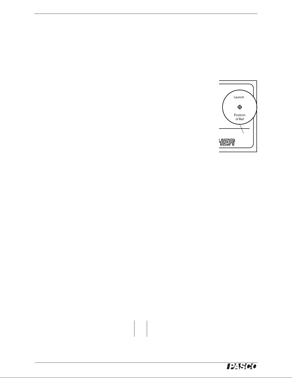
floor. Record this distance in the Data Table.
• The “Launch Position of Ball” in the barrel is marked on the label on the side of the
Launcher.
4. Use a plumb bob to find the point on the floor that is directly beneath the release point
on the barrel. Measure the horizontal distance along the floor from the release point to
the leading edge of the piece of white paper. Record the distance in the Data Table.
5. Carefully remove the carbon paper and measure from the leading edge of the white
paper to each of the ten dots. Record these distances in the Data Table and find the average. Calculate and record the total horizontal distance (distance to paper plus average distance from edge of
paper to dots).
6. Using the vertical distance, y, and the total horizontal distance, x, calculate the time of flight, t, and the initial
horizontal speed of the ball, v
. Record the time and speed in the Data Table.
0
Part B: Predicting the Range of a Ball Shot at an Angle
1. Adjust the angle of the Projectile Launcher to an angle between 30 and 60 degrees. Record this angle in the
second Data Table.
2. Using the initial speed and vertical distance from the first part of this experiment, calculate the new time of
flight and the new horizontal distance based on the assumption that the ball is shot at the new angle you have
just selected. Record the predictions in the second Data Table.
3. Draw a line across the middle of a white piece of paper and tape the paper on the floor so that the line on the
paper is at the predicted horizontal distance from the Projectile Launcher. Cover the white paper with carbon
paper (carbon side down) and tape the carbon paper in place.
4. Shoot the ball ten times.
5. Carefully remove the carbon paper. Measure the distances to the ten dots and record the distances in the sec-
ond Data Table.
Analysis
1. Calculate the percent difference between the predicted theoretical distance (“A”) and the actual average distance (“B”) when shot at an angle.
2. Estimate the precision of the predicted range. How many of the final 10 shots landed within this range?
12
012-05375C
Page 17
®
Model No. ME-6830 Exp. 1: Projectile Motion
Data Table A: Determine the Initial Speed
Vertical distance = __________ ___ Horizontal distance to edge of paper = _________________
Calculated time of flight = ________________ Initial speed = _____________
Trial Distance
1
2
3
4
5
6
7
8
9
10
Average
Total Distance
Data Table B: Predict the Range
Angle above horizontal = _____________ Horizontal distance to edge of paper = _________________
Calculated time of flight = ________________ Predicted range = _____________
Trial Distance
1
2
3
4
5
6
7
8
9
10
Average
Total Distance
012-05375C 13
Page 18

Projectile Launcher Exp. 1: Projectile Motion
®
Notes
14
012-05375C
Page 19

®
Model No. ME-6830 Exp. 2: Projectile Motion Usin g Photogates
yy0v0sint
1
2
-- -
gt
2
–+=
Exp. 2: Projectile Motion Using Photogates
Equipment Needed
Item Item
Projectile Launcher and plastic ball Plumb bob and string
Photogate Head ME-9498A (2) Photogate Mounting Bracket ME-6821A
PASCO Interface or Timer* PASCO Data acquisition software*
Meter stick Carbon paper
White paper Sticky tape
*See the PASCO web site at www.pasco.com for information about PASCO interfaces, timers, and data acquisition software.
Purpose
The purpose of this experiment is to predict and verify the range of a ball launched at an angle. Photogates are
used to determine the initial speed of the ball.
Theory
T o predict where a ball will land on the floor when it is shot from the Launcher at some angle above the horizontal,
it is first necessary to determine the initial speed (muzzle velocity) of the ball. The speed can be determined by
shooting the ball and measuring a time using photogates. To predict the range, x, of the ball when it is shot with an
initial speed at an angle, , above the horizontal, first predict the time of flight using the equation for the vertical
motion:
where y
equation to find the time, t. Use x = (v
is the initial height of the ball and y is the position of the ball when it hits the floor. Solve the quadratic
0
cos t to predict the range.
0
• NOTE: For best results, see the notes on “Repeatable Results” in the Introduction.
Setup
1. Put the Launcher in the top position on the Ballistic Pendulum upright. Clamp the Ballist ic Pendulum/Projectile Launcher to a sturdy table or other horizontal surface. Mount the Launcher near one end of the table aimed
away from the table.
2. Adjust the angle of the Projectile Launcher to an angle between 30 and 60 degrees and record the angle.
3. Attach the photogate mounting bracket to the Launcher and attach two photogates to the bracket. Check that
the distance between the photogates is 0.10 m (10 cm).
4. Plug the photogates into an interface or a timer.
Procedure
Part A: Determining the Initial Speed of the Ball
1. Put a plastic ball in the Projectile Launcher and use the ramrod to cock it at the long range position.
2. Setup the data acquisition software or the timer to measure the time between the ball blocking the two photo-
gates.
3. Shoot the ball three times and calculate the average of these times. Record the data in Data Table 2.1.
012-05375C 15
Page 20

Projectile Launcher Exp. 2: Projectile Motion Using Photogates
®
Bottom
of ball
yy0v0sint
1
2
-- -
gt
2
–+=
4. Calculate the initial speed of the ball based on the 0.10 m distance between the photogates. Record the value.
Data Table: Part A
Table 2.1: Determine the Initial Speed
Trial Time
1
2
3
Average Time
Initial Speed
Part B: Predicting the Range of a Ball Shot at an Angle
1. Keep the angle of the Projectile Launcher at the original angle above horizontal.
2. Measure the vertical distance from the bottom of the ball as it leaves the barrel to the
floor. Record this distance in Data Table 2.2.
• The “Launch Position of Ball” in the barrel is marked on the label on the side of the
Launcher.
3. Use the vertical distance, the angle, and the initial speed to calculate the time of flight.
Record the value.
4. Use the time of flight, t, angle, , and initial speed, v
(range, x = (v
cos t). Record the predicted range.
0
, to predict the horizontal distance
0
5. Draw a line across the middle of a white piece of paper and tape the paper on the floor so the line is at the predicted horizontal distance. Cover the white paper with carbon paper and tape the carbon paper in place.
6. Use a plumb bob to find the point on the floor that is directly beneath the release point on the barrel. Measure
the horizontal distance along the floor from the release point to the leading edge of the piece of white paper.
Record the distance in the Data Table.
7. Shoot the ball ten times.
8. Carefully remove the carbon paper and measure from the leading edge of the white paper to each of the ten
dots. Record these distances in the Data Table and find the average. Calculate and record the total horizontal
distance (distance to paper plus average distance from edge of paper to dots).
Angle above horizontal = ______________ Horizontal distance to edge of paper = _______________
Calculated time of flight = _________________ Predicted range = ________________
16
012-05375C
Page 21

®
Model No. ME-6830 Exp. 2: Projectile Motion Usin g Photogates
AB–
AB+
2
-------------
-------------
x100
Data Table: Part B
Table 2.2: Confirm the Predicted Range
Trial Distance
1
2
3
4
5
6
7
8
9
10
Average
Total Distance
Analysis
1. Calculate the percent difference between the predicted theoretical distance (“A”) and the actual average distance (“B”) when shot at an angle.
1. Estimate the precision of the predicted range. How many of the final 10 shots landed within this range?
012-05375C 17
Page 22

Projectile Launcher Exp. 2: Projectile Motion Using Photogates
®
Notes
18
012-05375C
Page 23

®
Model No. ME-6830 Exp. 3: Projectile Rang e versus Angle
θ
x
υ
0
Figure 3.1: Shooting on a level surface
v
y
0 v0singt
peak
–==
t 2t
peak
2
v
0
sin
g
----------------
==
θ
x
υ
0
y
0
Figure 3.2: Shooting from a table
yy0v0sint
1
2
-- -
gt
2
–+=
Exp. 3: Projectile Range versus Angle
Equipment Needed
Item Item
Projectile Launcher and plastic ball Plumb bob and string
Meter stick or measuring tape Box to make landing area same elevation as muzzle
Graph paper Carbon paper
White paper Sticky tape
Purpose
The purpose of this experiment is to determine how the range of the ball depends on the launch angle. The angle
that gives the greatest range is determined for two cases: for shooting on level ground and for shooting off a table.
Theory
The range is the horizontal distance, x, between the muzzle of the Launcher and the place where the projectile hits,
given by x = (v
above horizontal, and t is the time of flight. See the figure.
cos t, where v0 is the initial speed of the projectile as it leaves the muzzle, is the launch angle
0
For the case in which the projectile hits on a surface that is the same level as the level of the muzzle of the
Launcher, the time of flight of the projectile will be twice the time it takes for the projectile to reach the peak of its
trajectory. At the peak, the vertical speed is zero, so:
where v
is the initial speed of the projectile. Solving for the time gives an expression for the total time of flight as:
0
For the case in which the projectile is launched at an
angle above horizontal from a table onto the floor, the
time of flight is found using the equation for vertical
motion:
where y
is the initial height of the projectile in the
0
Launcher and y is the vertical position of the ball when
it hits the floor.
Setup
1. Put the Launcher in the top position on the Ballistic Pendulum upright. Clamp the Ballist ic Pendulum/Projectile Launcher to a sturdy table or other horizontal surface. Mount the Launcher near one end of the table, but
aim it toward the center of the table rather than away from the table.
012-05375C 19
Page 24

Projectile Launcher Exp. 3: Projectile Range versus Angle
®
CAUTION!
DO NOT LOOK
DOW
N BARREL!
CAUTION!
DO NOT LOOK
DOW
N BARREL!
C
A
U
T
IO
N!
DO
N
O
T LO
O
K
D
O
W
N
T
H
E
B
A
R
R
E
L.
L
O
N
G
R
A
N
G
E
M
E
D
I
U
M
R
A
N
G
E
S
H
O
R
T
R
A
N
G
E
P
o
s
i
t
i
o
n
o
f
B
a
l
l
L
a
u
n
c
h
SHORT RANGE
PROJECTILE LAUNCHER
ME-6800
Y
e
llow Ban
d i
n W
indow
Ind
ic
ates R
an
ge.
90
8
0
7
0
6
0
5
0
40
3
0
20
1
0
0
WEAR
SAFETY
GLASSES
WHEN IN USE.
U
s
e
2
5
m
m
b
a
l
l
s
O
N
L
Y
!
Figure 3.3: Shooting to a level surface
2. Adjust the angle of the Projectile Launcher to
10 degrees.
3. Put a plastic ball into the Projectile Launcher
and cock it to the medium or long range setting.
• Note: In general, the experiment will not work
as well on the short range setting because the
muzzle speed is more variable with the change
in angle.
4. Fire one shot to locate where the ball hits. Place
a box or other horizontal surface at that location
so the ball will hit the top of the box at the same
level as the muzzle of the launcher.
Procedure
Part A: Shooting to a Level Surface
1. Fire one shot to locate where the ball hits the top of the box. Tape a piece of white paper on the box at this
location. Tape a piece of carbon paper (carbon-side down) on top of the white paper.
• When the ball hits the carbon paper it will leave a mark on the white paper underneath.
2. Fire five shots.
3. Use a measuring tape to measure the horizontal distance from the muzzle to the leading edge of the paper. (If
a measuring tape is not available, use a plumb bob to find the point on the table that is directly beneath the
release point on the barrel and mea sure the distance along the table from the muzzle to the leading edge of the
paper.) Record the distance in the Data Table.
4. Carefully remove the carbon paper. Measure from the leading edge of the paper to each of the five dots and
record these distances in the Data Table.
5. Increase the launch angle by 10 degrees and repeat all the steps.
6. Keep repeating for angles up to and including 80 degrees (the complementary angle of 10 degrees).
Table 3.1: Shooting to a Level Surface
Angle 1020304050607080
1
2
3
4
5
Horizontal Distance
Average
Paper distance
Total distance
Part B: Shooting Off the Table
1. Turn the Projectile Launcher so it will launch the ball to the floor.
20
012-05375C
Page 25

®
Model No. ME-6830 Exp. 3: Projectile Rang e versus Angle
2. Repeat the procedure and record the data in the Data Table.
Table 3.2: Shooting off the Table
Angle 1020304050607080
1
2
3
4
Horizontal Distance
5
Average
Paper distance
Total distance
Analysis
1. Find the average of the five distances in each case and record the results in the Data Tables.
2. Add the average distance to the distance from the Launcher to the leading edge of the white paper to get the
total distance (range) in each case. Record the results in the Data Tables.
3. For each Data Table, plot the range versus the angle and draw a smooth curve through the points.
Questions
1. From the graph, what angle give the maximum range for each case?
2. Is the angle for the maximum range greater or less for shooting off the table?
3. Is the maximum range further when the ball is shot off the table or on the level?
Notes
012-05375C 21
Page 26

Projectile Launcher Exp. 3: Projectile Range versus Angle
®
22
012-05375C
Page 27

®
Model No. ME-6830 Exp. 4: Projectile Path
t
x
v
0
---- -
=
y
1
2
-- -
gt
2
=
2
2v
0
2
--------
x
2
=
g
2v
0
2
--------
CAUTIO
N!
D
O NO
T LOO
K
DO
W
N BA
RREL!
CAUTIO
N!
D
O NO
T LOO
K
DO
W
N BA
RREL!
C
A
U
T
I
O
N
!
D
O
N
O
T
L
O
O
K
D
O
W
N
T
H
E
B
A
R
R
E
L
.
L
ON
G
RANGE
ME
DIUM
R
AN
GE
SHOR
T
RANG
E
P
o
s
i
t
i
o
n
o
f
B
a
l
l
L
a
u
n
c
h
SHOR
T RANGE
PROJECTILE LAUNCHER
ME-6800
Y
e
l
l
o
w
B
a
n
d
in
W
i
n
d
o
w
In
d
i
c
a
t
e
s
R
a
n
g
e
.
9
0
8
0
7
0
6
0
50
4
0
3
0
2
0
1
0
0
W
E
A
R
S
A
F
E
T
Y
G
L
A
S
S
E
S
W
H
E
N
I
N
U
S
E
.
U
s
e
2
5
m
m
b
a
ll
s
O
N
L
Y
!
Figure 4.1: Launcher setup
Target board
y
x
Exp. 4: Projectile Path
Equipment Needed
Item Item
Projectile Launcher and plastic ball Movable vertical target board*
Meter stick or measuring tape Sticky tape
Graph paper Carbon paper
White paper
*The target board should be as tall as the distance from the muzzle to the floor.
Purpose
The purpose of this experiment is to determine how the vertical distance a projectile drops is related to the horizontal distance the projectile travels when the projectile is launched horizontally .
Theory
The range is the horizontal distance, x, between the muzzle of the Launcher and the place where the projectile hits,
given by x = v
t, where v0 is the initial speed of the projectile as it leaves the muzzle and t is the time of flight.
0
If the projectile is launched horizontally, the time of flight of the projectile will be
The vertical distance, y, that the projectile falls during time, t, is given by
where g is the acceleration due to gravity. Substituting for t in the second equation gives
2
A plot of y versus x
will give a straight line with a slope equal to .
Setup
1. Clamp the Projectile Launcher
to a sturdy table or other horizontal surface. Mount the
Launcher near one end of the
table with the Launcher aimed
away from the table.
2. Adjust the angle of the Projec-
tile Launcher to zero degrees
so the ball will be launched
horizontally.
3. Fire a test shot on medium
range to determine the initial
position of the vertical target
board. Place the target board
on the floor so that the ball hits the board near the bottom. See Figure 4.1
012-05375C 23
Page 28

Projectile Launcher Exp. 4: Projectile Path
®
4. Cover the target board with white paper. Tape carbon paper over the white paper.
Procedure
1. Measure the vertical height from the floor to the muzzle and record the height in the Table 4.1. Mark this
height on the target.
2. Measure the horizontal distance from the muzzle of the Launcher to the target board and record it in the Data
Table.
3. Shoot the ball.
4. Move the target board about 10 to 20 cm closer to the Launcher.
5. Repeat steps 2 through 4 until the height of the ball when it strikes the target board is about 10 to 20 cm below
the height of the muzzle.
Data Table 4.1
Height of Muzzle = ____________________
Table 4.1: x, y Data
Horizontal (x) Vertical (y) x
2
Analysis
1. On the target board, measure the vertical distances from the muzzle level mark down to the ball marks and
record them in Table 4.1.
2. Calculate x2 for all the data points and record them in the Data Table.
3. Plot a graph of y versus x2 and draw the best-fit light through th e data points.
4. Calculate the slope of the graph and record it in Table 4.2.
5. From the slope of the graph, calculate the initial speed of the ball as it leaves the muzzle. Record the initial
speed in Table 4.2.
6. Pick any x, y data point from Table 4.1. Use the vertical distance, y, to calculate the time, t. Calculate the ini-
tial speed using this time and the horizontal distance, x. Record the results in Table 4.2.
24
012-05375C
Page 29

®
Model No. ME-6830 Exp. 4: Projectile Path
AB–
AB+
2
-------------
------------------ -
x100
7. Calculate the percent difference between the two initial speeds that were found using the different methods.
Record the percent difference in Table 4.2. (To calculate the percent difference, let A be one of the initial
speed values and let B be the other initial speed value.)
Data Table 4.2
Table 4.2: Compare Methods for Initial Speed
Item Value
Slope of graph
Initial speed from slope
Time of flight
Initial speed from x,y
Percent difference
Question
1. From the graph, was the best-fit line straight?
2. What does the shape of the best-fit line on the y versus x
2
graph tell you about the relationship of y and x2?
3. If you plotted a graph of y versus x, how would the graph differ from the y versus x
4. What shape is the path of the projectile?
2
graph?
012-05375C 25
Page 30

Projectile Launcher Exp. 4: Projectile Path
®
Notes
26
012-05375C
Page 31

®
Model No. ME-6 830 Exp. 5: Conservation of Energy
CAUTION!
DO NOT LOOK
DOWN BARREL!
CAUTION!
DO NOT LOOK
DOWN BARREL!
CAUTION!
DO NOT LOOK
DOWN THE BARREL.
LONG
RANGE
MEDIUM
RANGE
SHORT
RANGE
Position
of Ball
Launch
SHORT RANGE
PROJECTILE LAUNCHER
ME-6800
Yellow Band in Window
Indicates Range.
90
8
0
7
0
6
0
5
0
40
3
0
20
10
0
WEAR
SAFETY
GLASSES
WHEN IN USE.
Use 25 mm
balls ONL Y!
Figure 5.1: Conservation
of Energy
final
position
initial
position
h
v
0
KE
1
2
-- -
mv
0
2
=
GPE mgh=
y
x
υ
0
Figure 5.2: Find the initial speed
y
1
2
-- -
gt
2
=
t
2y
g
----- -=
v
0
x
t
--
=
Exp. 5: Conservation of Energy
Equipment Needed
Item Item
Projectile Launcher and plastic ball Plumb bob and string
Meter stick or measuring tape Sticky tape
White paper Carbon paper
Photogate Head ME-9498A (2) optional* Photogate Mounting Bracket ME-6821A optional*
*Use the Photogates and Photogate Mounting Bracket with a PASCO Interface or Timer to measure the initial speed of the ball
directly (see Experiment 2).
Purpose
The purpose of this experiment is to confirm that the initial kinetic energy of a
projectile shot straight up is transformed into an equal amount of gravitational
potential energy.
Theory
The total mechanical energy of a projectile is the sum of its gravitational potential energy and its kinetic energy. In the absence of friction, total mechanical
energy is conserved. When a projectile is shot straight up, the initial gravitational
potential energy (GPE) can be defined as zero. The initial kinetic energy (KE)
depends on the mass, m, of the projectile and the initial speed, v
:
0
When the projectile reaches its maximum height, h, the speed of the projectile is
zero and therefore the kinetic energy is zero. The gravitational potential energy
depends on the mass of the projectile and the height:
where g is the acceleration due to gravity. If friction in the form of air resistance is ignored, the initial kinetic
energy should equal the final gravitational potential energy.
The initial speed of the projectile must be determined in order to calculate the initial kinetic energy. To calculate
the initial speed, v
, of a projectile fired horizontally, the horizontal distance travelled by the projectile is x = v0t
0
where t is the time that the projectile is in the air.
The vertical distance that projectile drops in
time, t, is given by
The initial speed of the projectile can be calculated by measuring x and y and using y to calculate the time, t. The time of flight of the
projectile can be found using
and then the initial speed can be found using
012-05375C 27
Page 32

Projectile Launcher Exp. 5: Conservation of Energy
®
Setup
1. Clamp the Projectile Launcher to a sturdy table or other horizontal surface. Mount the Launcher near one end
of the table with the Launcher aimed away from the table.
2. Point the Launcher straight up and fire a test shot on medium range to make sure that the ball doesn’t hit the
ceiling. (If it does, use the short range setting for this experiment or put the Launcher closer to the floor.)
3. Adjust the angle of the Projectile Launcher to zero degrees so the ball will be launched horizontally.
Procedure
Part A: Determine the Initial Speed (without photogates)
1. Put the plastic ball into the Launcher and cock it to the medium range setting. Fire one shot to locate where the
ball hits the floor. At that position, tape a piece of white paper to the floor. Place a piece of carbon paper (carbon-side down) on top of the white paper and tape it in place
• When the ball hits the carbon paper, it will leave a mark on the white paper.
2. Fire ten shots.
3. Measure the vertical distance from the bottom of the ball as it leaves the barrel to the floor. Record this dis-
tance in the Table 5.1. Use the distance to calculate the time of flight and record it.
• The “Launch Position of Ball” in the barrel is marked on the label on the side of the Launcher.
4. Use a plumb bob to find the point on the floor that is directly beneath the release point on the barrel. Measure
the horizontal distance along the floor from the release point to the leading edge of the piece of white paper.
Record the distance in Table 5.1.
5. Carefully remove the carbon paper. Measure from the leading edge of the white paper to each of the ten dots
and record these distances in Table 5.1.
6. Find the average of the ten distances and record it.
7. Using the horizontal distance and the time of flight, calculate the initial speed of the ball. Record the speed.
Table 5.1:
Item Value Item Value
Vertical distance Calculated time of flight
Horizontal distance to edge of paper Initial speed
28
012-05375C
Page 33

®
Model No. ME-6 830 Exp. 5: Conservation of Energy
Table 5.1
Trial Distance Trial Distance
16
27
38
49
510
Average
Total distance
Alternate Method for Determining the Initial Speed of the Ball (using photogates)
1. Attach the photogate mounting bracket to the Launcher and attach two photogates to the bracket. Check that
the distance between the photogates is 0.10 m (10 cm).
2. Plug the photogates into an interface or a timer.
3. Adjust the angle of the Launcher to 90 degrees (straight up).
4. Put a plastic ball in the Projectile Launcher and use the ramrod to cock it at the medium range setting.
5. Setup the data acquisition software or the timer to measure the time between the ball blocking the two photo-
gates.
6. Shoot the ball three times and calculate the average of these times. Record the data in the Table 5.2.
7. Calculate the initial speed of the ball based on the 0.10 m distance between the photogates. Record the value.
Table 5.2
Table 5.2: Initial Speed Using Photogates
Trial Time
1
2
3
Average Time
Initial Speed
012-05375C 29
Page 34

Projectile Launcher Exp. 5: Conservation of Energy
®
KE GPE–
KE GPE+
2
--------------------------
-------------------------- -
x100
Part B: Measure the Height of the Ball
1. Adjust the angle of the Launcher to 90 degrees (straight up).
2. Shoot the ball on the medium range setting several times and then measure the maximum heigh t attained by
the ball. Record the maximum height in Table 5.3.
3. Determine the mass of the ball and record it in Table 5.3.
Analysis
1. Calculate the initial kinetic energy and record it in Table 5.3.
2. Calculate the final gravitational potential energy and record it in Table 5.3.
3. Calculate the percent difference between the initial kinetic energy and the final gravitational potential energy
and record it in Table 5.3.
Table 5.3: Results
Item Value
Maximum height of ball
Mass of ball
Initial Kinetic Energy
Final Potential Energy
Percent difference
Questions
1. How does the initial kinetic energy compare to the final gravitational potential energy?
2. How does friction in the form of air resistance affect the result for the conservation of energy?
3. When the Launcher is cocked, it has elastic potential energy. If energy is conserved, how should the elastic
potential energy compare to the initial kinetic energy?
30
012-05375C
Page 35

®
Model No. ME-6830 Exp. 6: Conservation of M omentum
υ
0
m
1
m
2
(υ = 0)
(a)
θ
1
υ
1
m
1
θ
2
υ
2
m
2
(b)
Figure 6.1: Conservation of Momentum
(a) before collision (b) after collision
P
before
m1v0x
ˆ
=
x
ˆ
P
after
m1v1xm2v
2x
+xˆm1v1ym2v
2y
+y
ˆ
+=
m1v
1y
m2v
2y
–=
m1v
0
m1v1xm2v
2x
+=
1
2
-- -
m
1v0
2
1
2
-- -
m
1v1
2
1
2
-- -
m
2v2
2
+=
Exp. 6: Conservation of Momentum
Equipment Needed
Item Item
Projectile Launcher and 2 plastic balls 2-D Collision Accessory
Meter stick or measuring tape Sticky tape
White paper, large sheet Carbon paper (2 or 3 sheets)
Protractor Plumb bob and string
Purpose
The purpose of this experiment is to confir m that moment um is conserved for elastic and inelastic collisions in two
dimensions.
Theory
A ball is shot toward another ball that is initially at rest,
resulting in a collision after which the two balls move in
different directions. In the system consisting of just the
balls, both balls are falling under the influence of gravity
so momentum is not conserved in the vertical direction.
However, there is no net force in the horizontal plane (if
air resistance is ignored), so momentum is conserved in
the horizontal plane.
Before collision, since all the momentum is in the direction of Ball #1 (m
), it is convenient to define the x-axis in
1
this direction. Momentum before the collision is:
where v
is the initial speed of Ball #1 and is the unit vector in the x-direction. The momenta of the two balls
0
after the collision consists of both horizontal and vertical components, so the momentum after the collision is:
where v
= v1 cos 1, v1y = v1 sin 1. v2x = v2 cos 2, and v2y = v2 sin 2.
1x
Since there is no momentum in the y-direction before the collision, there is zero net momentum in the y-direction
after the collision. Therefore, t
Equating the momentum in the x-direction before the collision to the momentum in th e x-directi on after the collision gives:
In a perfectly elastic collision, kinetic energy is conserved as well as momentum.
Also, when energy is conserved, the paths of two balls of equal mass will be at right angles to each other after the
collision.
012-05375C 31
Page 36

Projectile Launcher Exp. 6: Conservation of Momentum
®
Target
ball
“tee”
Setup
1. Clamp the Projectile Launcher to a sturdy table. Mount the
Launcher near one end of the table with the Launcher
aimed inward toward the table.
2. Adjust the angle of the Projectile Launcher to zero degrees
so the ball will be launched horizontally onto the table.
3. Cover the table with white paper (such as butcher paper).
NOTE: The paper must reach the base of the Launcher.
4. Fire a test shot on the short range setting to make sure that
the ball lands on the table. Tape a piece of carbon paper
(carbon-side down) over the spot where the ball lands.
5. Mount the 2-D Collision Accessory to the front of the
Launcher.. Put a target ball on the post (“tee”) of the accessory.
6. Loosen the thumbscrew and rotate the 2-D Collision Accessory slightly to one side.
• The “tee” must be located so that the launched ball does not rebound into the Launcher but does hit the target
ball so that both balls land on the table at the same time.
• Tighten the thumbscrew to hold the accessory in place.
7. Load the Launcher and fire a test shot to check that both balls hit the table at the same time. Tape a piece of
carbon paper on the white paper at each spot where the two balls land on the table.
Procedure
A. No Collision
1. Put “ball 1” into the Launcher and cock it to the short range setting. Do not put a target ball on the “tee”.
2. Shoot the ball straight ahead and repeat the procedure five times.
B. Elastic Collision
1. Use two balls. Load Ball 1into the Launcher at the short range setting. Place Ball 2 on the “tee” of the 2-D
Collision Accessory.
2. Shoot Ball 1 so it collides with the target ball (Ball 2). Repeat the procedure five times.
C. Inelastic Collision
1. Use two balls. Load Ball 1into the Launcher at the short range setting. Put a small loop of sticky tape
(sticky-side out) on Ball 2 and place it on the “tee”.
2. Orient the tape side of Ball 2 so that it will be struck by the launched ball (Ball 1), causing an inelastic collision.
3. Fire a test shot to locate where the two balls hit the table. Tape a piece of carbon paper to the white paper.
4. Shoot Ball 1 and if the two balls stick together but miss the carbon paper, relocate the carbon paper and shoot
once more.
32
012-05375C
Page 37

®
Model No. ME-6830 Exp. 6: Conservation of M omentum
• Since the tape does not produce the same inelastic collision each time, it is only useful to record this collision
once.
5. Use a plumb bob to locate on the paper the spot directly below the point of contact of the two balls. Mark this
spot on the paper as the “point-of-contact” spot. Carefully remove the carbon paper from the white paper.
Analysis
The time of flight for each shot is the same because the vertical distance for each shot is the same. Therefore, the
horizontal length of each path is proportional to the speed of the ball. Since the masses are the same, the horizontal
length of each path is also proportional to the momentum of the ball.
A. No Collision
1. Draw straight lines from the “point-of-contact” spot to each of the dots made by the ‘no collision’ shots.
2. Measure each straight line and record the length. Find the average of the five lengths and record the length as
the “initial x-momentum” in Table 6.1 and Table 6.2. (For example, if the length is 65 cm, record “65” as the
value for the “initial x-momentum” but do not include any units.)
B. Elastic Collision
1. Draw a straight line from the “point-of-contact” through the center of the group of dots made by the ‘no colli-
sion’ shots. (This is the center line from which all of the angles will be measured.)
2. Draw straight lines from the “point-of-contact” spot to each of the dots made by the ‘elastic collision’ shots.
(There should be five lines on each side of the center line.)
3. Measure from the “point-of-contact” to each of the dots made by Ball 1. Find the average of the five lengths.
Draw a straight line from the “point-of-contact” through the center of the group of dots made by Ball 1.
4. Measure the angle from the centerline to the straight line for Ball 1. Use this angle and the average length of
the line for Ball 1 to calculate the x-component for Ball 1 and the y-component for Ball 1. Record the values.
5. Measure from the “point-of-contact” to each of the dots made by Ball 2. Find the average of the five lengths.
Draw a straight line from the “point-of-contact” through the center of the group of dots made by Ball 2.
6. Measure the angle from the centerline to the straight line for Ball 2. Use this angle and the average length of
the line for Ball 2 to calculate the x-component for Ball 2 and the y-component for Ball 2. Record the values.
7. Add the x-momentum for Ball 1 and the x-momentum for Ball 2 and record the result in Table 6.1 as “Final
x-momentum”.
8. Calculate the initial kinetic energy of Ball 1 and the sum of the kinetic energy of Ball 1 and Ball 2 after the
collision.
9. Calculate the percent differences.
Table 6.1: Data for the Elastic Collisions
Item Value Item Value Percent difference
Initial x-momentum.
Ball 1
Final y-momentum,
Ball 1
Initial kinetic energy,
Ball 1
Final x-momentum,
Ball 1 + Ball 2
Final y-momentum,
Ball 2
Final kinetic energy,
Ball 1 + Ball 2
012-05375C 33
Page 38

Projectile Launcher Exp. 6: Conservation of Momentum
®
C. Inelastic Collision
1. Draw straight lines from the “point-of-contact” spot to the dots made by the ‘inelastic collision’ shot. (Th e re
should be two lines.)
2. Measure from the “point-of-contact” to each of the dots made by the ‘inelastic collision’ shot.
3. Measure the angle from the centerline to the straight line for each dot of the ‘inelastic collision’ shot.
4. Use the angle and the length of the lines for the shot to calculate the x-component and the y-component for
each ball in the ‘inelastic collision’ shot. Record the values.
5. After the collision, add the x-momentum for Ball 1 and the x-momentum for Ball 2 and record the result in
Table 6.2 as “Final x-momentum”.
6. Calculate the initial kinetic energy of Ball 1 and the sum of the kinetic energy of Ball 1 and Ball 2 after the
collision.
7. Calculate the percent differences.
Table 6.2: Data for the Inelastic Collisions
Item Value Item Value Percent difference
Initial x-momentum.
Ball 1
Final y-momentum,
Ball 1
Initial kinetic energy,
Ball 1
Final x-momentum,
Ball 1 + Ball 2
Final y-momentum,
Ball 2
Final kinetic energy,
Ball 1 + Ball 2
Questions
1. Was momentum conserved in the x-direction for each type of collision?
2. Was momentum conserved in the y-direction for each type of collision?
3. W as kinetic energy conserved for the elastic collision?
4. W as kinetic energy conserved for the inelastic collision?
5. For the elastic collision, was the angle between the paths of the balls after the collision equal to 90 degrees as
expected?
6. For the inelastic collision, what was the angle between the paths of the balls after the collision? Why is it less
than 90 degrees?
34
012-05375C
Page 39

®
Model No. ME-6830 Exp. 7: Vary the Angle to Maxim ize the Height
θ
C
A
U
TIO
N!
D
O
N
O
T LO
O
K
D
O
W
N BAR
R
E
L!
C
A
U
TIO
N!
D
O
N
O
T LO
O
K
D
O
W
N BAR
R
E
L!
CAUTION!
DO NOT LOOK
DOWN THE
L
O
N
G
R
A
N
G
E
M
E
D
I
U
M
R
A
N
G
E
S
H
O
R
T
R
A
N
G
E
P
o
s
i
t
i
o
n
o
f
B
a
l
l
L
a
u
n
c
h
SHOR
T RANGE
P
R
O
J
E
C
T
IL
E
L
A
U
N
C
H
E
R
ME-6800
Y
e
l
l
o
w
B
a
n
d
i
n
W
i
n
d
o
w
In
d
ic
a
t
e
s
R
a
n
g
e
.
9
8
7
6
5
4
3
2
1
0
WEAR
SAFETY
GLASSES
WHEN IN USE.
Us
e 25 m
m
ba
lls
ON
L
Y
!
Figure 7.1: Maximizing Height
Range
Initial
height
Angle
Initial
speed
y
y
0
v
0
x
yy0v0sint
1
2
-- -
gt
2
–+=
xv0cost=
t
x
v
0
cos
-----------------
=
yy0x
gx
2
2v
o
2
2
cos
---------------------- -
–tan+=
dy
d
------
x
2
gx2
2
sectan
v
0
2
----------------------------------
–sec 0==
max
tan
v
0
gx
----- -
2
=
Exp. 7: Vary the Angle to Maximize the Height
Equipment Needed
Item Item
Projectile Launcher and plastic ball Board to protect wall
Meter stick or measuring tape Sticky tape
White paper, large sheet Carbon paper (several sheets)
Plumb bob and string
Purpose
The purpose of this experiment is to find the launch angle that will maximize the height on a vertical wall for a
projectile launched at a fixed horizontal distance from the wall.
Theory
When the ball is shot at an angle at a fixed distance, x, from a
target such as a vertical wall, the ball hits the wall at a height y
given by:
where y
is the initial height of the ball, v0 is the initial speed
0
of the ball as it leaves the muzzle, is the angle of inclination
above horizontal, g is the acceleration due to gravity, and t is
the time of flight. The range is the horizontal distance, x,
between the muzzle of the Launcher and the place where the
ball hits, given by
Solving this equation for the time of flight, t, gives
Substituting for t in the equation for y gives
T o find the angle, , that gives the maximum height, y, find the first derivative of the equation for y and set it equal
to zero. Solve for the angle, .
Solving for the angle, , gives:
Since the second derivative is negative for
the fixed distance, x, and the maximum height, y
max
, and x.
, the angle is a maximum. To find the initial speed of the ball, use
max
. Solve the y-equation for v0 and plug in the values for y
max
max
,
012-05375C 35
Page 40

Projectile Launcher Exp. 7: Vary the Angle to Maximize the Height
®
Difference
AB–
AB+
2
-------------
-------------
x100=
Setup
1. Clamp the Projectile Launcher to a sturdy table. Mount the Launcher near one end of the table with the
Launcher aimed toward a wall about 2 meters from the table.
2. Use a vertical board to the protect the wall and cover the board with white paper.
3. Fire a test shot to see where the ball hits the board and tape a piece of carbon paper (carbon-side down) at that
position.
Procedure
1. Shoot the ball at various angles and pinpoint whi c h angle gives the maximum height by checking the marks
on the white paper. (Move the carbon paper as necessary.)
2. Measure the angle that produces the maximum height and record its value in Table 7.1.
3. Measure the maximum height and record the value in the Data Table.
4. Measure the horizontal distance from the muzzle to the vertical board and record the value.
5. Measure the initial height of the ball where it leaves the muzzle and record the value..
Table 7.1: Data and Results
Item Value
Measured Angle for Maximum Height
Maximum Height
Horizontal Distance
Initial Height
Calculated Initial Speed
Calculated Angle for Maximum Height
Percent Difference between Angles
Analysis
1. Calculate the initial speed by solving the y-equation for v0 and substituting the values for y
from Table 7.1.
2. Calculate the angle for maximum height using the initial speed calculated in step 1 and the horizontal distance
from the wall to the launcher.
3. Calculate the percent difference between the measured angle and the calculated
angle. (Let A be one of the angles and B be the other angle).
max
,
max
, and x
Questions
1. For the angle that gives the maximum height, when the ball hits the wall, has it already reached the peak of its
trajectory?
2. For what distance from the wall would the height be maximized for a launch angle of 45°? What would the
maximum height be in this case?
36
012-05375C
Page 41

®
Model No. ME-6 830 Exp. 8: Projectile Velocity—Approximate Method
v
b
M
m
---- -
2gR
cm
1 cos–=
String loop
R
cm
Figure 8.1: Setup
Exp. 8: Projectile Velocity—Approximate Method
Equipment Needed
Item Item
Ballistic Pendulum/Projectile Launcher Steel ball
C-clamp Mass balance
String
Purpose
The muzzle velocity of the projectile launcher is determined by launching the ball into the ballistic pendulum and
observing the angle to which the pendulum swings.
As derived earlier in the manual, the equation for the velocity of the ball is approximately:
where M is the mass of the pendulum and ball combined, m is the mass of the ball, g is the acceleration due to
gravity, R
by the pendulum after the collision.
is the distance from the pivot point to the center of mass of the pendulum, and is the angle reached
cm
Setup
1. Put the Projectile Launcher on the Ballistic Pendulum upright at the level of the ball catcher (the low position). Make sure that the pendulum can hang vertically without touching the launcher.
2. Clamp the Ballistic Pendulum base to a sturdy table. Make sure that the clamp does not interfere with the pendulum swing.
Procedure
1. Latch the pendulum at 90° so it is out of the way temporarily, and then load the projectile launcher with the
steel ball. Allow the pendulum to hang freely, and move the angle indicator to zero degrees.
2. Fire the launcher and record the angle reached. If you want to do the experiment with a lower or higher angle,
add to or remove mass from the pendulum. Repeat these test measurements until you are satisfied with the
mass of the pendulum.
3. Once you have chosen the mass to use for your experiments, remove the pendulum from the upright by
unscrewing and removing the axle. Use a mass balance to find the mass of the pendulum and ball together.
Record this value as M in Table 8.1.
4. Measure the mass of the ball alone and record this as m.
• Tie a loop in a piece of string, and hang the pendulum horizontally from the loop. (See Figure 8.1.) With the
ball latched in position in the ball catcher, adjust the position of the pendulum in the loop until the pendulum
balances. Measure the distance from the pivot point to this balance point, and record the distance as R
cm
..
012-05375C 37
Page 42

Projectile Launcher Exp. 8: Projectile Velocity—Approximate Method
®
• NOTE: It may be easier to balance the pendulum on the edge of a ruler or similar object.
5. Reattach the pendulum to the upright, making sure that it is facing the right way. Be sure that the angle indicator is in front of the long pin of the pendulum.
6. Load the launcher, and then set the angle indicator to an angle one or two degrees less than the angle reached
in step 2. This will nearly eliminate the friction against the pendulum caused by the angle indicator, since the
pendulum will only move the angle indicator for a short distance.
7. Fire the launcher, and record the angle reached by the pendulum in T able 8.1. Repeat several times, setting the
angle indicator to an angle one or two degrees less than the previous angle reached by the pendulum each
time.
Table 8.1
M = ____________________ m = ____________________ Rcm = ___________________
Table 8.1: Data
Item Value
1
2
3
4
5
Average
Muzzle velocity
Calculations
1. Find the average angle reached by the pendulum and record the value in Table 8.1.
2. Calculate the muzzle velocity of the ball fired from the projectile launcher.
Questions
1. Is there another way to measure the muzzle velocity that you could use to check your results? You may want
to use that second method and compare the two answers.
2. What sources of error are there in this experiment? How much do these errors affect your result?
3. It would simplify the calculations if kinetic energy were conserved in the collision between the ball and the
pendulum (see “Ballistic Pendulum Theory” in the Introduction). What percentage of the kinetic energy is lost
in the collision between the ball and pendulum? Would it be valid to assume that energy was conserved in that
collision?
4. How does the angle reached by the pendulum change if the ball is not caught by the ball catcher? Y ou may test
this by turning the pendulum around so the ball strikes the back of the ball catcher. Is there more energy or
less energy transferred to the pendulum?
38
012-05375C
Page 43

®
Model No. ME-6830 Exp. 9: Projectile Velocity—Exact Method
v
b
1
mR
b
----------
2IMgR
cm
1 cos–=
I
MgR
cm
T
2
4
2
------------------------
=
Exp. 9: Projectile Velocity—Exact Method
Equipment Needed
Item Item
Ballistic Pendulum/Projectile Launcher and steel ball Ruler
C-clamp Mass balance
String Stopwatch
Purpose
The muzzle velocity of the projectile launcher is determined by launching the ball into the ballistic pendulum and
observing the angle to which the pendulum swings.
As derived earlier in the manual, the equation for the velocity of the ball is approximately:
where M is the mass of the pendulum and ball combined, m is the mass of the ball, g is the acceleration due to
gravity, R
pivot point to the ball, is the angle reached by the pendulum, and I is the moment of inertia of the pendulum with
the ball in the catcher.
is the distance from the pivot point to the center of mass of the pendulum, Rp is the distance from the
cm
The value of I can be found by measuring the period of small oscillations of the pendulum/ball combination and by
using the equation:
where T is the period.
Setup
1. Put the Projectile Launcher on the Ballistic Pendulum upright at the level of the ball catcher (the low position). Make sure that the pendulum can hang vertically without touching the launcher.
2. Clamp the Ballistic Pendulum base to a sturdy table. Make sure that the clamp does not interfere with the pendulum swing.
Procedure
1. Latch the pendulum at 90° so it is out of the way temporarily, and then load the projectile launcher with the
steel ball. Allow the pendulum to hang freely, and move the angle indicator to zero degrees.
2. Fire the launcher and record the angle reached. If you want to do the experiment with a lower or higher angle,
add to or remove mass from the pendulum. Repeat these test measurements until you are satisfied with the
mass of the pendulum.
3. Once you have chosen the mass to use for your experiments, remove the pendulum from the upright by
unscrewing and removing the axle. Use a mass balance to find the mass of the pendulum and ball together.
Record this value as M in Table 9.1.
4. Measure the mass of the ball alone and record this as m.
012-05375C 39
Page 44

Projectile Launcher Exp. 9: Projectile Velocity—Exact Method
®
String loop
R
cm
Figure 9.1: Setup
5. Tie a loop in a piece of string, and hang the pendulum horizontally from the loop. (See Figure 9.1.) With the
ball latched in position in the ball catcher, adjust the position of the pendulum in the loop until the pendulum
balances. Measure the distance from the pivot point to this balance point, and record the distance as R
cm
.
• NOTE: It may be easier to balance the pendulum on the edge of a ruler or similar object.
6. Measure the distance between the pivot point and the center of the ball. Record this as R
.
b
7. Remove the launcher so that the pendulum can swing freely. With the ball in the ball catcher, give the pendulum an initial displacement of 5° or less. Using the stopwatch, time how long it takes to go through ten oscillations. Divide this time by the number of oscillations and record the result as T in Table 9.1.
8. Calculate the value of I, and record it in Table 9.1.
9. Reattach the launcher and load it. Set the angle indicator to an angle one or two degrees less than the angle
reached in step 2. This will nearly eliminate the friction against the pendulum caused by the angle indicator,
since the pendulum will only move the angle indicator for a short distance.
10. Fire the launcher, and record the angle reached by the pendulum in Table 9.1. Repeat several times, setting the
angle indicator to an angle one or two degrees less than the previous angle reached by the pendulum each
time.
Table 9.1
M = ____________________ m = ____________________ Rcm = ___________________
R
= ____________________ T = ____________________ I = _____________________
b
Table 9.1: Data
Item Value
1
2
3
4
5
Average
Muzzle velocity
Calculations
1. Find the average angle reached by the pendulum and record the value in Table 9.1.
2. Calculate the muzzle velocity of the ball fired from the projectile launcher.
40
012-05375C
Page 45

®
Model No. ME-6830 Exp. 9: Projectile Velocity—Exact Method
v
b
M
m
---- -
2gR
cm
1 cos–=
Questions
1. Is there another way to measure the muzzle velocity that you could use to check your results? You may want
to use that second method and compare the two answers.
2. What sources of error are there in this experiment? How much do these errors affect your result?
3. It would simplify the calculations if kinetic energy were conserved in the collision between the ball and the
pendulum (see “Ballistic Pendulum Theory” in the Introduction). What percentage of the kinetic energy is lost
in the collision between the ball and pendulum? Would it be valid to assume that energy was conserved in that
collision?
4. Does increasing the mass of the pendulum increase or decrease the efficiency of the energy transfer in the collision? Try it.
5. The “Projectile Velocity—Approximate Method” experiment uses the approximate equation for velocity:
• What is the value of velocity when you use this equation? Is there a significant difference between these two
calculated values? What factors would increase the difference between these two results? How would you
build a ballistic pendulum so that the approximate equation gave better results?
012-05375C 41
Page 46

Projectile Launcher Exp. 9: Projectile Velocity—Exact Method
®
42
012-05375C
Page 47

®
Model No. ME-6830 Exp. 10 (Demo ): Do 30° and 60° Give the Same Range?
t 2t
peak
2v0sin
g
------------------- -
==
x
2v
0
2
cossin
g
------------------------------- -
=
x
v
0
2
2sin
g
------------------- -
=
CAUTION!
DO
NO
T LOO
K
D
OW
N BARREL!
CAUTION!
DO
NO
T LOO
K
D
OW
N BARREL!
C
A
U
T
IO
N
!
D
O
N
O
T L
O
O
K
D
O
W
N
T
H
E
B
A
R
R
E
L
.
L
O
N
G
R
A
N
G
E
M
E
D
I
U
M
R
A
N
G
E
S
H
O
R
T
R
A
N
G
E
P
osition
of Ball
Laun
ch
S
H
O
R
T
R
A
N
G
E
PROJECTILE LAUNCHER
M
E
-6
8
0
0
Y
e
l
l
o
w
B
a
n
d
i
n
W
i
n
d
o
w
I
n
d
i
c
a
t
e
s
R
a
n
g
e
.
9
0
8
0
70
6
0
5
0
40
3
0
2
0
1
0
0
W
E
A
R
S
A
F
E
T
Y
G
L
A
S
S
E
S
W
H
E
N
IN
U
S
E
.
U
s
e
2
5
m
m
ba
lls
O
N
L
Y
!
Figure 10.1: Set up to shoot on level surface.
Box
Exp. 10 (Demo): Do 30° and 60° Give the Same Range?
Equipment Needed
Item Item
Projectile Launcher and steel ball Box to make landing area same height as muzzle
Purpose
The purpose of this demonstration is to confirm that the range of a ball launched at 30° is the same as one launched
at 60° if the ball lands at the same height from which it was launched.
Theory
The range is the horizontal distance, x, between the muzzle of the Launcher and the place where the projectile
lands, given by x = (v
above horizontal, and t is the time of flight.
If the ball lands on a target that is at the same height as the level of the muzzle of the launcher, the time of flight of
the ball will be twice the time it takes the ball to reach the peak of its trajectory, when its vertical component of
speed reaches zero.
cos ) t where v0 is the initial speed of the ball as it leaves the muzzle, is the launch angle
0
where g is the acceleration due to gravity. Substituting for t in the equation for x gives:, and t is the time of flight.
and using a trigonometry identity gives:
The ranges for the angles 30° and 60° are the same since sin 60° = sin 120°.
Setup
1. Clamp the Projectile Launcher to a sturdy
table. Mount the Launcher near one end of
the table with the Launcher aimed toward
the middle of the table.
2. Adjust the angle of the Launcher to 30°.
3. Put the steel ball into the Launcher and cock
it to the medium range or long range setting.
• NOTE: In general, this demonstration will
not work as well on the short range setting because the muzzle speed is more variable with the change in
angle.
4. Fire a test shot to see where the ball hits. Place the box in front of that location so that the next ball will hit the
top of the box.
Procedure
1. Shoot the ball at 30° to demonstrate that the ball lands on the box.
012-05375C 43
Page 48

Projectile Launcher Exp. 10 (Demo): Do 30° and 60° Give the Same Range?
®
2. Change the angle of the Launcher to 60° and shoot the ball again . Call attent ion to the fact that the ball again
lands on the box (confirming that the ranges are the same).
3. Change the angle to 45° and shoot the ball again to show that the ball now lands further away, missing the
box.
4. Ask the question: What other pairs of angles will have a common range? Will 20° and 70° have the same
range? Will 35° and 55° have the same range?
• This demonstration can be done for any two angles that add up to 90°.
44
012-05375C
Page 49

®
Model No. ME-6 830 Exp. 11 (Demo): Sim ultaneous Shots at Different Speeds
t
2y
g
----- -=
y
x
short
x
long
υ
0(long)
υ
0(short)
Figure 9.1: Shots fired simultaneously
Exp. 11 (Demo): Simultaneous Shots at Different Speeds
Equipment Needed
Item
Projectile Launcher (2) and plastic ball (2)
Purpose
The purpose of this demonstration is to confirm that regardless of the initial speed of projectiles fired horizontally,
the projectiles will hit the floor at the same time.
Theory
Two projectiles are shot horizontally from the same height, y. The muzzle speeds of the two projectiles are different.
The vertical and horizontal motions of a projectile are independent of each other. The horizontal distance, x, travelled by the projectile depends on the initial speed, v
The time of flight depends on the vertical distance that the projectile falls.
, and the time of flight, t. The distance x = v0t.
0
where g is the acceleration due to gravity. Since the vertical distance is the same fore each projectile, the time of
flight is the same for each projectile.
Setup
1. Clamp two Projectile Launchers adjacent to
each other on a sturdy table. Mount the
Launchers near one end of the table with the
Launchers aimed away from the table so the
balls will land on the floor.
2. Adjust the angle of the Launcher to 0° so
the balls will fire horizontally.
Procedure
1. Put a plastic ball into each Launcher. Cock one Launcher to the short range setting and clock the other
Launcher to the long range setting.
2. Ask the class to be quiet and listen for the balls striking the floor.
• NOTE: If there is only one click, that means that the balls hit the floor simultaneously.
3. Put both trigger release strings in the same hand and pull them at the same time so that the balls are launched
simultaneously.
4. After the balls hit the floor, ask the class if they heard one click or two.
012-05375C 45
Page 50

Projectile Laun cher Exp. 11 (Demo): Simultaneous Shots at Different Sp eeds
®
46
012-05375C
Page 51

®
Model No. ME-6830 Exp. 12 (Demo): Shooting Through Hoops
xv0t=
yy
0
1
2
-- -
– gt
2
=
yy
0
1
2
-- -
– g
x
v
0
---- -
2
ax2b+==
Exp. 12 (Demo): Shooting Through Hoops
Equipment Needed
Item Item
Projectile Launcher and plastic ball Ring clamp on stand (5)
Photogate Head ME-9498A (2) optional Photogate Mounting Bracket ME-6821A optional
Meter stick Two-meter stick
Purpose
The purpose of this demonstration is to confirm that the part of a projectile is parabolic.
Theory
The range is the horizontal distance, x, between the muzzle of a Launcher and the place where the projectile hits,
given by:
where v
is the initial speed of the projectile as it leaves the muzzle and t is the time of flight. The vertical position,
0
y, of the projectile at time t is given by:
where y0 is the initial height of the projectile and g is the acceleration due to gravity.
Solving the x-equation for t and substituting the expression in the y-equation gives:
2
where “a” and “b” are constants. The y-equation (y = ax
+b) describes a parabola.
Pre-Lab
Before the demonstration begins, find the initial speed of the bal. Use two photogates and a photogate mounting
bracket with a P ASCO Interface or T imer or shoot the ball horizontally and measure x and y. (Use y to calculate the
time of flight. See experiments 1 and 2.)
Setup
1. Clamp the Projectile Launcher to a sturdy table near one end of the table with the Launchers aimed away from
the table so the balls will land on the floor.
2. Adjust the angle of the Launcher to 0° so the balls will fire horizontally.
Procedure
1. Measure and record the initial height, y0, of the ball at muzzle level.
012-05375C 47
Page 52

Projectile Launcher Exp. 12 (Demo): Shooting Through Hoops
®
C
A
U
T
IO
N
!
D
O
N
O
T
LO
O
K
D
O
W
N
B
A
R
R
E
L
!
C
A
U
T
IO
N
!
D
O
N
O
T
LO
O
K
D
O
W
N
B
A
R
R
E
L
!
C
A
U
T
I
O
N
!
D
O
N
O
T
L
O
O
K
D
O
W
N
T
H
E
L
O
N
G
RA
N
G
E
M
E
D
IU
M
R
A
N
G
E
S
H
O
R
T
R
A
NG
E
P
o
s
i
t
io
n
o
f
B
a
l
l
L
a
u
n
c
h
S
H
O
R
T R
A
N
GE
PROJECTILE LAUNCHER
M
E-6800
Y
e
l
l
o
w
B
a
n
d
i
n
W
i
n
d
o
w
I
n
d
i
c
a
t
e
s
R
a
n
g
e
.
9
8
7
6
5
4
3
2
1
0
W
EAR
SAFETY
GLASS
ES
WHEN
IN US
E.
U
s
e
2
5
m
m
b
a
ll
s
O
N
L
Y
!
ME-6831
BALLISTIC PENDULUM
Figure 12.1: Demonstration setup
2. Calculate and record the horizontal and vertical positions of the ball each 1/10 second until the vertical posi-
tion is zero.
Table 10.1: X- and y-positions
t (sec) x = v
t (cm) y = y0 - (1/2)gt2 (cm)
0
0.1
0.2
0.3
0.4
0.5
3. Lay the two-meter stick on the floor in a straight line away from the Launcher. Remove the back mounting
screw from the Launcher base so that the back of the Launcher can rotate upward. Look through the Launcher
at the end of the two-meter stick. Adjust the end of the stick until the end is aligned with the sites in the
Launcher and the stick is along the path of the ball when it is fired.
4. Starting at the muzzle of the Launcher, measure off each set of x and y distances and place a ring clamp on a
stand at each position corresponding to one-tenth of a second (see Figure 10.1).
5. Shoot the ball through the rings.
6. Ask the class: What shape of curve is formed by the rings? What is the path of the projectile?
48
012-05375C
Page 53

®
Model No. ME-6830 Exp. 13 (Demo): Ela stic and Inelastic Collisions
Exp. 13 (Demo): Elastic and Inelastic Collisions
Equipment Needed
Item
Projectile Launcher and plastic or steel ball
Purpose
The purpose of this demonstration is to show the difference in kinetic energy transfer between an elastic collision
and an inelastic collisions.
Theory
The amount of kinetic energy transferred between colliding objects depends on the elasticity of the collision. By
reversing the pendulum of the Ballistic Pendulum so the ball bounces off instead of being caught, it is possible to
demonstrate this effect.
Setup
1. Clamp the Ballistic Pendulum/Projectile Launcher to a sturdy table with the launcher mounted in the lower
position on the upright.
Procedure
1. Shoot the ball into the pendulum and record the angle reached.
2. Remove the pendulum and reinstall it in the reversed position so that the ball opening is away from the
launcher.
3. Shoot the same ball again at the same launcher setting and note the angle reached.
Analysis
• The collision between the ball and the pendulum is not perfectly elastic, so kinetic energy is still not conserved. However, the collision is more nearly elastic than the completely inelastic collision in step 1. There is
a greater transfer of kinetic energy.
012-05375C 49
Page 54

Projectile L auncher Exp. 13 (Demo): Elastic and Inelastic Collisions
®
50
012-05375C
Page 55

®
Model No. ME-6830 Teacher’s Guide
t
v
0
v0sin22gy0y–++sin
g
---------------------------------------------------------------------------------- -
=
Teacher ’s Guide
Exp. 1: Projectile Motion
NOTE: For best results, make sure that the Launcher is securely clamped to a sturdy table. Any movement of the
Launcher will result in inconsistent data.
The muzzle speed of the Launcher tested was 6.5 m/s (on the long range setting).
To find the range at the chosen angle, it is necessary to solve the quadratic equation given in the Theory section.
The solution is:
Analysis
1. The difference depended on the angle at which the Launcher was fired. The table gives typical results: range
Angle Predicted Range Actual Range Percent Error
30 5.22 5.19 0.57%
45 5.30 5.16 2.64%
60 4.35 4.23 2.87%
39 5.39 5.31 1.48%
NOTE: The maximum angle is not 45° in this case. The range at 60° is not equal to the range at 30°. This is
because the initial height of the ball is not the same as the impact point. The maximum range for this setup
(with the Launcher 1.15 m above ground level) was calculated to be at 39°. This was verified experimentally.
2. Answers will vary depending on the method for estimating the precision. The primary source of error is ignoring the effect of air resistance.
Exp. 2: Projectile Motion Using Photogates
Except for the method of determining initial speed, this experiment is identical to ex periment 1.
012-05375C 51
Page 56

Ballistic Pendulum/Projectile Launcher Teacher’s Guide
®
0
0.5
1
1.5
2
2.5
3
3.5
4
4.5
0 102030405060708090
Range (m)
Angle (degrees)
0
1
2
3
4
5
6
0 102030405060708090
Range (m)
Angle (degrees)
Exp. 3: Projectile Range Versus Angle
Procedure
• Shooting off a level surface:
• Shooting off a table:
• NOTE: The curves show the calculated ranges in each case. The data points are the actual measured ranges.
Questions
1. On a level surface, the maximum range is at 45°. For a non-level surface, the angle of maximum range
depends on the initial height of the projectile. For the experimental setup, with an initial height of 1.15 m, the
maximum range is at 40° (versus the theoretical value of 39°).
2. The angle of maximum range decreases with table height.
3. The maximum distance increases with table height.
Exp. 4: Projectile Path
Analysis
1. Alternately, measure your distances from the ground up.
52
012-05375C
Page 57

®
Model No. ME-6830 Teacher’s Guide
0
0.05
0.1
0.15
0.2
0.25
0 0.2 0.4 0.6 0.8 1 1.2 1.4 1.6 1.8 2
Vertical Distance (m)
Horizontal Distance Squared (m^2)
f(x) = -1.181345E-1*x + 2.609457E-1
R^2 = 9.997926E-1
g
2v
0
2
--------
2. Vertical distances were measured from the ground up for this graph. The intercept is the height of the launcher
above the ground when done this way.
3. The slope (measuring from the ground) is -0.118 for this example. Measuring down from the initial height
will give the same value, except positive.) In either case, the slope is:
4. The slope calculated here gives us an initial speed of 6.44 m/s. This compares favorably with the speed calculated in experiments 1 and 2.
5. Results will vary with this method: the point of the activity is that individual measurements are not as accurate
as a large number of measurements and a curve fit.
Questions
1. Yes. This tells us that y is a function of x
2
.
2. A plot of y versus x would be parabolic instead of linear.
3. The projectile moves in a parabolic curve (if air resistance is neglected).
Exp. 5: Conservation of Energy
Analysis
1. Using the photogate method, the initial speed of the ball was found to be 4.93 m/s (for the short range
launcher at the medium range setting). The ball mass was 9.6 g, so the total kinetic energy was 0.117 J.
2. The ball reached an average height of 1.14 m (above the muzzle). The gravitational potential energy was
0.107 J.
3. The energy difference was 8.5% of the original kinetic energy.
4. NOTE: It seems unlikely that this much energy is lost due to air resistance, especially when you consider the
extraordinarily good results for labs 3 and 4. It is likely that the error here enters the calculation in the actual
measurements of initial velocity and maximum height.
012-05375C 53
Page 58

Ballistic Pendulum/Projectile Launcher Teacher’s Guide
®
yy0x
max
gx
2
2v
0
2
2
max
cos
------------------------------- -
–tan+=
dy
dx
----- -
max
gx
2
v
0
2
2
max
cos
------------------------------ -
–tan=
Exp. 6: Conservation of Momentum in Two Dimensions
Setup
• If possible, use medium range setting instead of the short range setting. The medium range setting gives more
predictable results than the short-range setting.
Analysis
• Results for the x component of momentum should be within 5% of initial values. The total y component
should be very small compared to the x component.
Questions
1. Momentum is conserved on both axes.
2. Kinetic energy is nearly conserved in the elastic collision. There is some loss of energy which indicates that
the collision is not perfectly elastics.
3. Momentum is conserved for the inelastic collision, but kinetic energy is not conserved.
4. The angle should be nearly 90°. (Trials had angles of about 84°.)
5. In the inelastic case, the angle will be less than in the elastic case. The exact angle will depend on the degree
of inelasticity, which will depend on the type and amount of tape used.
Exp. 7: Vary the Angle to Maximize the Height
Procedure
1. Yo u should be able to measure the angle of maximum height to within ±2%.
2. Measure the distance to the front edge of the ball.
3. Measure the initial height to the center of the ball.
Analysis
1. The initial speed should be close to the initial speed determined by other methods. You may wish to determine
the initial speed by the method in experiment 1, and use that value in your calculations for the rest of the
experiment.
2. Measured value and calculated vale should agree to within 3%.
Questions
1. The ball will have passed its peak by the time it reaches the wall. To show this, take the derivative of y with
respect to x:
54
012-05375C
Page 59

®
Model No. ME-6830 Teacher’s Guide
max
v
0
2
gx
max
--------------
1–
tan=
dy
dx
----- -
v
0
2
gx
max
--------------
gx
v
0
2
v
0
2
gx
max
--------------
1–
tan
2
cos
--------------------------------------------------------
–=
a
b
-- -
1–
tan
cos
b
a
2b2
+
---------------------
=
dy
dx
----- -
v
0
2
gx
max
--------------
gx
v
0
2
gx
max
v
0
4
g2x
max
2
+
-------------------------------- -
2
-----------------------------------------------
–
v
0
2
gx
max
--------------
xv
0
4
g2x
2
max
+
v
0
2
gx
max
2
---------------------------------------
–==
dy
dx
----- -
v
0
gx
max
--------------
v
0
x
gx
2
max
-----------------
–
gx
v
0
2
----- -
–=
dy
dx
----- -
x
max
gx
max
v
0
2
--------------
–=
max
tan
v
0
2
gx
----- -
x
v
0
2
g
---- -
==
yy
0
v
0
2
g
---- -
g
v
0
2
g
---- -
2
v
0
2
----------------
–+ y
0
v
0
2
g
---- -
v
0
2
g
---- -
–+==
yy
0
=
• substitute
• Substitute
• and simplify:
•When x = x
, the value of this derivative is negative.
max
• Therefore, the ball has already reached the peak and is on its way down.
2. Solve the equation for maximum angle to determin e x:
• Substitute this value into the equation for y to determine the maximum height.
Exp. 8: Projectile Motion—Approximate Method
Procedure
1. The exact mass used is not critical. Pick a value that gives a fairly large swing for best results.
2. With the steel ball and extra masses on the pendulum, the balance point will be somewhere on the ball catcher
itself. This makes it difficult to use string, but it is relatively easy to find the center of mass by balancing the
pendulum on a straightedge.
3. The angle reached by the pendulum should not vary by more than one degree between successive trials.
012-05375C 55
Page 60

Ballistic Pendulum/Projectile Launcher Teacher’s Guide
®
Calculations
• Use the equations given in the theory section for the approximate method.
Questions
1. The best other method of measuring velocity is described in the first part of experiment 1.
2. The greatest source of error is the equation used. This is an approximate equation, based on the assumption
that the masses involved are point masses. The amount of effect this equation has on the results will depend
on the exact geometry of the pendulum and ball, and should be between five and eight percent.
3. Typically, 70% of the kinetic energy of the ball is ‘lost’. It is not valid to assume that kinetic energy is conserved.
Exp. 9: Projectile Motion—Exact Method
Procedure
1. The exact mass is not critical. Pick a value that gives a fairly large swing for best results.
2. With the steel ball and extra masses on the pendulum, the balance point will be somewhere on the ball catcher
itself. This makes it difficult to use string, but it is relatively easy to find the center of mass by balancing the
pendulum on a straightedge.
3. Measure this period as exactly as possible, using the smallest measurement angle that is practical.
4. The angle reached by the pendulum should not vary more than one degree between successive trials.
Calculations
• Use the equations given in the theory section for the approximate method.
Questions
1. The best other method of measuring velocity is described in the first part of experiment 1.
2. Sources of error include friction and measurement error.
3. Typically, 70% of the kinetic energy of the ball is ‘lost’. It is not value to assume that kinetic energy is con-
served.
4. The energy transfer is less efficient when there is a larger difference in the masses involved.
5. The exact method will give results that are typically within 2.5% of the actual value.
56
012-05375C
Page 61

®
Model No. ME-6830 Technical Support
Technical Support
For assistance with any PASCO product, contact PASCO at:
Address: PASCO scientific
10101 Foothills Blvd.
Roseville, CA 95747-7100
Phone: 916-786-3800 (worldwide)
800-772-8700 (U.S.)
Fax: (916) 786-7565
Web: www.pasco.com
Email: support@pasco.com
For more information about the Ballistic Pendulum/Projectile Launcher and the latest revision of this Instruction
Manual, visit the PASCO web site and enter ME-6830 or ME-6831 into the Search window.
Limited Warranty For a description of the product warranty, see the PASCO catalog.
Copyright The PASCO scientific 012-05375C Ballistic Pendulum/Projectile Launcher Instruction Manual is copyrighted with all rights
reserved. Permission is granted to non-profit educational institutions for reproduction of any part of this manual, providing the reproductions are used only in their laboratories and classrooms, and are not sold for profit. Reproduction under any other circumstances,
without the written consent of PASCO scientific, is prohibited.
Trademarks PASCO and PASCO scientific are trademarks or registered trademarks of PASCO scientific, in the United States and/or
in other countries. All other brands, products, or service names are or may be trademarks or service marks of, and are used to identify, products or services of, their respective owners. For more information visit www.pasco.com/legal.
012-05375C 57
Page 62

Ballistic Pendulum/Projectile Launcher Technical Support
®
58
012-05375C
 Loading...