

Page 1

®
Instruction Manual with
Experiment Guide
012-09851A
Mini Launcher Ballistic Pendulum
ME-6829
Page 2

Mini Launcher Ballistic Pendulum Table of Contents
Contents
Introduction . . . . . . . . . . . . . . . . . . . . . . . . . . . . . . . . . . . . . . . . . . . . . . . . . . . . . . . . . . . 4
Equipment Set-up . . . . . . . . . . . . . . . . . . . . . . . . . . . . . . . . . . . . . . . . . . . . . . . . . . . . . . 4
Foam Insert Replacement . . . . . . . . . . . . . . . . . . . . . . . . . . . . . . . . . . . . . . . . . . . . . . . . 6
Experiment 1: Inelastic Collisions . . . . . . . . . . . . . . . . . . . . . . . . . . . . . . . . . . . . . . . . . . 7
Experiment 2: Ballistic Pendulum . . . . . . . . . . . . . . . . . . . . . . . . . . . . . . . . . . . . . . . . . . 9
Experiment 3: Conservation of Momentum and Energy . . . . . . . . . . . . . . . . . . . . . . . . 12
Technical Support . . . . . . . . . . . . . . . . . . . . . . . . . . . . . . . . . . . . . . . . . . . . . . . . . . . . . 18
Page 3
Mini Launcher Ballistic Pendulum
ME-6829
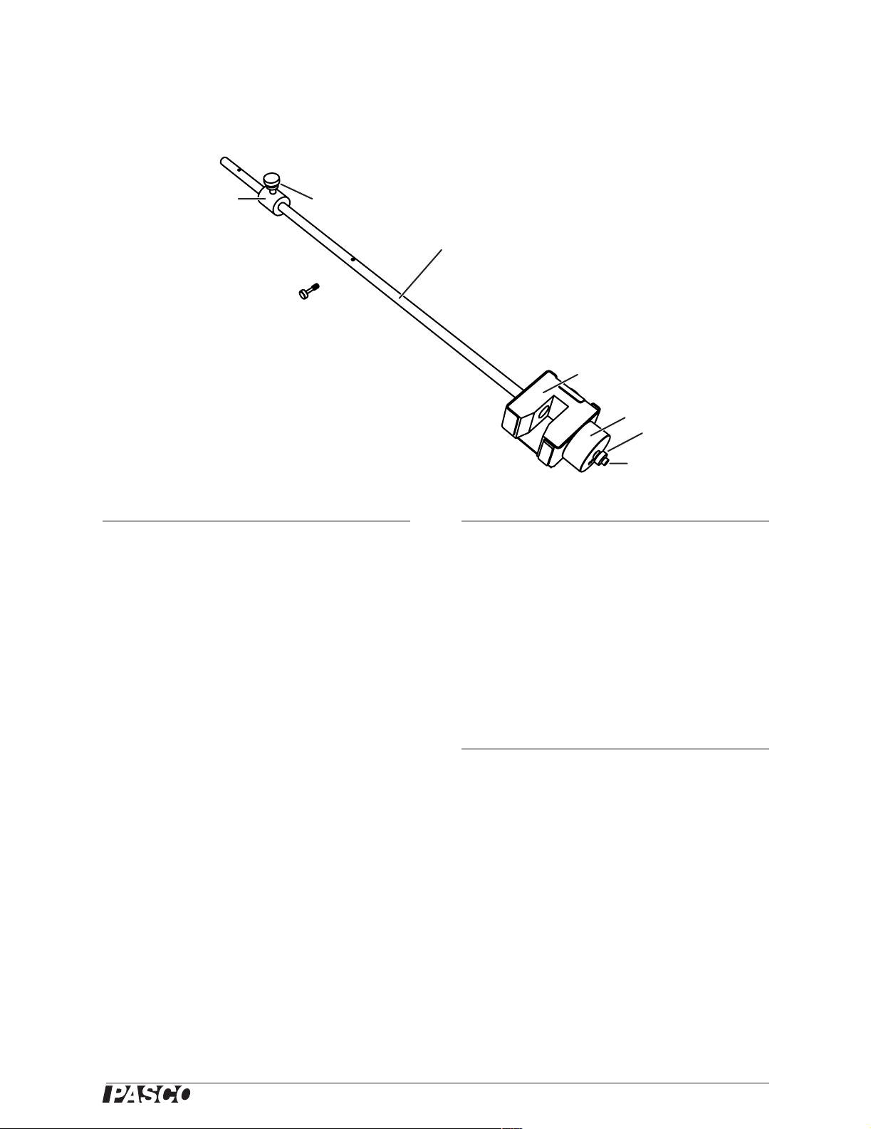
23
1
4
5
6
7
8
Included Equipment Part Number
1. Catcher and pendulum rod ME-6829
2. Sliding counterweight 648-09595
3. Counterweight set screw 613-047
4. Pendulum attachment
613-076
screw
5. Replaceable foam insert ME-6835
(5-pack)
6. Ballast mass 648-06511
7. Ballast lock nut 614-029
8. Ballast fastening screw 611-043
Required Equipment Part Number
Mini Launcher
(includes
ME-6825A
1
projectile)
PASPORT Rotary Motion
Sensor with three-step
2
pulley
PS-2120
Table Clamp ME-9472,
or similar
90 cm mounting rod ME-8738,
or similar
Optional Equipment
3
Photogates (qty. 2) ME-9498A,
or similar
Digital Adapter
2
PS-2159
Photogate Mounting Bracket ME-6821
Super Pulley with Clamp ME-9448A
Hanging mass ME-9348,
or similar
1
The new-style mounting bracket included with model
ME-6825A is required. If you have an older mini launcher
(model ME-6825), upgrade it with a model ME-6836 bracket.
2
Sensor requires a PASPORT interface.
3
For measuring launch velocity and rotational inertial. See
Experiment 3.
®
3
Page 4

Mini Launcher Ballistic Pendulum Introduction
Introduction
Use the Mini Launcher Ballistic Pendulum in combination with a Mini Launcher and
Rotary Motion Sensor (RMS) to measure the velocity of a steel ball. The Mini
Launcher shoots the ball into the Mini Launcher Ballistic Pendulum. The RMS measures the resulting angular displacement and velocity of the pendulum. The pendulum
can be configured to catch the ball or allow the ball to bounce off. Two pivot locations
and removable masses allow it to approximate a simple pendulum or a physical pendulum.
This manual includes set-up instructions and experiment instructions ranging from a
simple (Experiment 1) to more advanced (Experiment 3).
Equipment Set-up
Assemble the Apparatus
1. Set up the mini launcher, bracket, table clamp, mounting rod, and RMS as shown
in Figure 1. The exact position of the RMS is not important yet. Note that the side
of the RMS without the model number on the label is facing you. (If the RMS is
mounted the other way, it will measure negative displacement.)
ä
FOR
INTERFACES
ROTARY MOTION SENSOR
Mini
Launcher
Bracket
Table clamp
Figure 1: Launcher and RMS mounted on rod
RMS
Mounting
Rod
Three-step
pulley
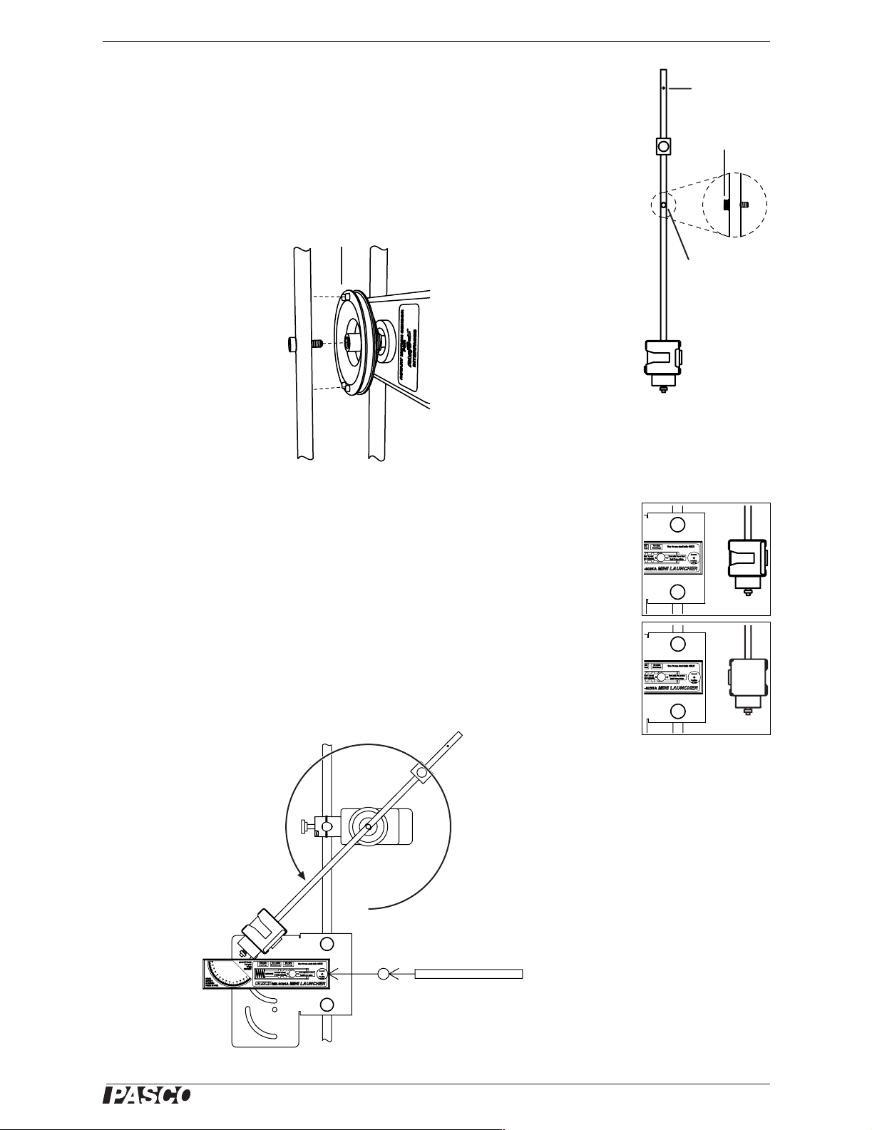
2. Slide the three-step pulley onto the RMS shaft with the largest pulley out as
shown in Figure 2.
4
Figure 2: Three-step
pulley on RMS
®
Page 5
Model No. ME-6829 Equipment Set-up
3. Select one of the holes on the pendulum rod: either the center hole or the end
hole. If you will be using the end hole, remove the counterweight. Also select a
End hole
side of the pendulum: either the catcher or the bumper. Thread the attachment
screw into the hole as shown in Figure 3. Screw it all the way in so it is loosely
captured.
Attachment
screw
4. Thread the screw into the end of the RMS shaft. Align the pendulum rod with the
tabs on the pulley as shown in Figure 4. Tighten the screw.
Align rod with tabs
Center hole
Figure 3: Attachment
Figure 3: Attachment
screw loosely captured
screw loosely captured
in center hole
in center hole
Figure 4: Attaching pendulum to RMS
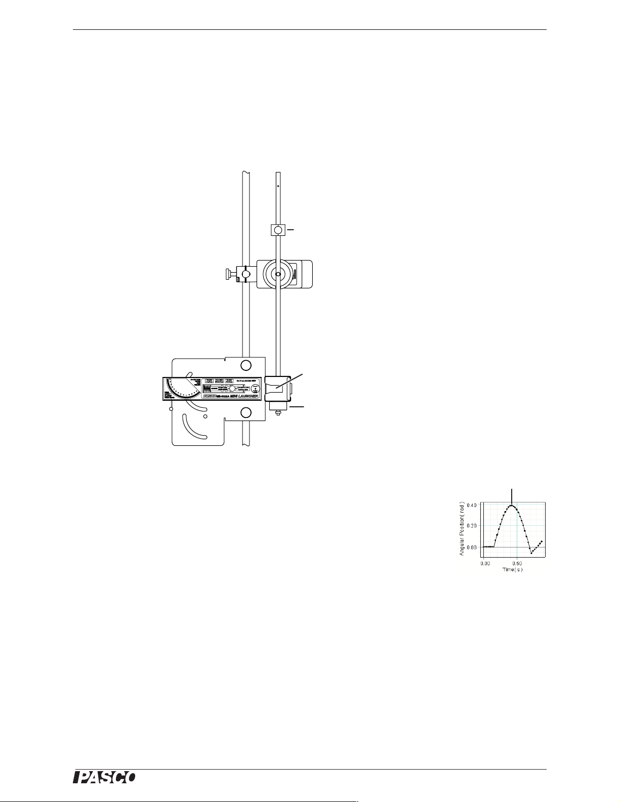
5. Adjust the position of the RMS so the pendulum is aligned with the launcher as
shown in Figure 5.
Load the Launcher
1. Swing the pendulum out of the way as shown in Figure 6.
2. Place the projectile (included with the launcher) in the end of the barrel.
3. Use the pushrod included with the launcher to push the ball down the barrel until
the trigger catches in the first, second, or third position (for a slow, medium, or
fast launch).
Swing pendulum
out of the way
Figure 5: Pendulum
aligned with launcher,
catcher side (top) and
bumper side (bottom)
PushrodBall
Figure 6: Loading the launcher
®
5
Page 6

Mini Launcher Ballistic Pendulum Foam Insert Replacement
4. Return pendulum to its normal hanging position.
Prepare the Sensor
1. Connect the RMS to a PASPORT interface. If you will be using a computer, con-
nect the interface to it and start DataStudio.
2. Set the sampling rate of the RMS to 40 Hz.
3. Prepare a graph to show angular position versus time.
For detailed instructions, refer to the documentation that came with your interface or
press F1 to launch DataStudio’s on-line help.
Test Fire
1. Start data recording.
2. Pull the trigger of the launcher.
3. Stop data collection.
Figure 7 shows typical data for an inelastic collision. If your data shows negative
angular displacement, disassemble the RMS from the mounting rod and pendulum
and remount it with the pendulum attached to the other end of the RMS shaft.
Foam Insert Replacement
With age and repeated use, the foam catcher insert may lose elasticity. If the catcher
does not reliably hold the ball, remove the foam insert and replace it with a new one
(PASCO part ME-6835).
Figure 7: Typical data
Figure 8: Removable foam insert
6
®
Page 7
Model No. ME-6829 Experiment 1: Inelastic Collisions
Experiment 1: Inelastic Collisions
Experiment Set-up
Set up the equipment and software as described on pages 4–6 with the pendulum rod
attached to the RMS at the center hole and the catcher side of the pendulum facing the
launcher. Place the counterweight on the pendulum rod midway between the RMS
shaft and the top end of the rod. Attach the ballast mass to the bottom of the catcher.
Counterweight
Catcher
side
Ballast
mass
Figure 1.1: Set-up for Part A
Part A: Completely Inelastic Collision (Ball Catch)
1. Load the launcher and push the ball in to the first (slowest) position.
2. Start data collection.
3. Pull the trigger to launch the ball so it is caught by the pendulum.
4. After the pendulum has swung out and back, stop collection.
5. Record the maximum angular displacement of the pendulum here. ___________
Maximum displacement
Figure 1.2: Typical data
®
7
Page 8

Mini Launcher Ballistic Pendulum Experiment 1: Inelastic Collisions
Part B: Partially Inelastic Collision (Ball Bounce)
1. Remove
the pendulum from the RMS. Reattach the pendu-
lum with the bumper facing the launcher. There should be a
gap of a few centimeters between the end of the launcher and
the bumper.
2. Predict what will happen. Will the maximum angular dis-
placement in this part be greater or less than in the maximum
displacement in Part A? _____________
3. Guess the maximum angle that the pendulum will swing to.
Record your prediction here. ______________
4. Start data collection.
5. Pull the trigger to launch the ball so it hits the pendulum and
bounces off.
6. After the pendulum swung out and back, stop collection.
7. Record the maximum angular displacement of the pendulum
here. ___________
Analysis
Bumper
side
Figure 1.3: Set-up for Part B
1. Was the maximum angular displacement in Part B greater or less than in
Part A? ______________
2. Was your prediction in Part B step 2 correct? ______________
3. Create a graph of angular velocity versus time showing the data from parts A and
B. Which type of collision (completely inelastic or partially inelastic) resulted in
the greater maximum velocity? ______________
4. Explain qualitatively how maximum velocity is related to maximum angular dis-
placement.
________________________________________________________________
________________________________________________________________
________________________________________________________________
________________________________________________________________
________________________________________________________________
________________________________________________________________
8
®
Page 9

Model No. ME-6829 Experiment 2: Ballistic Pendulum
Experiment 2: Ballistic Pendulum
Theory
The ballistic pendulum has historically been used to measure the launch velocity of a
high speed projectile. In this experiment, a projectile launcher fires a steel ball (of
mass m
As the momentum of the ball is transferred to the catcher-ball system, the pendulum
swings freely upwards, raising the center of mass of the system by a distance h.
The pendulum rod is hollow to keep its mass low, and most of the mass is concentrated at the end so that the entire system approximates a simple pendulum. During
the collision of the ball with the catcher, the total momentum of the system is conserved. Thus the momentum of the ball just before the collision is equal to the
momentum of the ball-catcher system immediately after the collision:
) at a launch velocity, V0. The ball is caught by a pendulum of mass m
ball
pend
.
(eq. 2.1)
m
ballV0
MV=
where V is the speed of the catcher-ball system just after the collision, and
(eq. 2.2) M = m
ball
+ m
pend
During the collision, some of the ball's initial kinetic energy is converted into thermal
energy. But after the collision, as the pendulum swings freely upwards, we can
assume that energy is conserved and that all of the kinetic energy of the catcher-ball
system is converted into the increase in gravitational potential energy.
2
1
(eq. 2.3)
where g =9.81 m/s
2
, and the distance h is the vertical rise of the center of mass of the
--2
MV
Mgh=
pendulum-ball system.
Combining equations 2.1 through 2.3 (eliminating V) yields
m
pend
(eq. 2.4)
⎛⎞
V
1
0
-------------+
⎝⎠
m
2gh=
ball
Experiment Set-up
1. Attach the ballast mass to the bottom of the catcher.
2. Set up the equipment and software as described on pages 4–6
with the pendulum rod attached to the RMS at the end hole and
the catcher side of the pendulum facing the launcher. Do not put
the sliding counterweight on the pendulum rod.
Procedure
Record Data
1. Load the launcher and push the ball in to the third (fastest) posi-
tion.
2. Start data collection.
®
Catcher
side
Ballast
mass
Figure 2.1: Set-up
9
Page 10
Mini Launcher Ballistic Pendulum Experiment 2: Ballistic Pendulum
3. Launch the ball so that it is caught in pendulum.
4. After the pendulum has swung out and back, stop data collection.
5. Note the maximum angular displacement measured by the RMS. Record it in
Table 2.1.
6. Repeat steps 1 through 5 several times.
7. Calculate the average maximum displacement, θ
max
.
Find the Mass and Center of Mass
1. Fire the ball one more time (without recording data). Stop the pendulum near the
top of its swing so it does not swing back and hit the launcher (this will prevent
the ball from falling out or shifting).
2. Remove the pendulum from the RMS.
3. Remove the screw from the pendulum shaft.
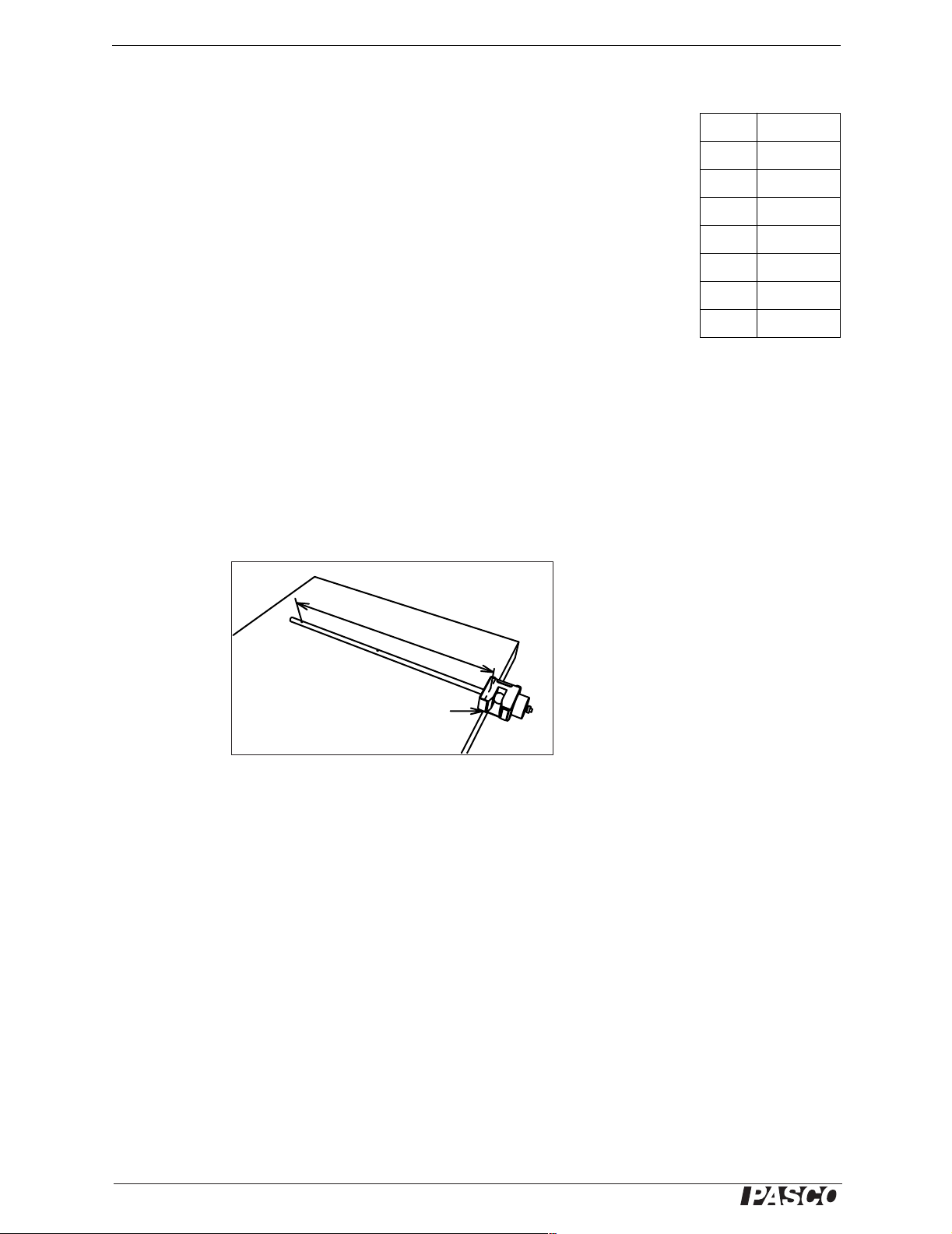
4. With the ball still in the catcher, place the pendulum at the edge of a table with
the pendulum shaft perpendicular to the edge and the counterweight hanging over
the edge. Push the pendulum out until it just barely balances on the edge of the
table. The balance point is the center of mass. (See Figure 2.1.)
Table 2.1: Maximum
Angular Displacement
Trial Angle
Trial 1
Trial 2
Trial 3
Trial 4
Trial 5
Trial 6
Avg:
θ
max
=
r
Balance point
Figure 2.1: Pendulum-ball system
balanced on table edge
5. Measure the distance, r, from the center of rotation (where the pendulum was
attached to the RMS) to the center of mass. r = _____________________.
6. Remove ball from the catcher.
7. Measure the mass of the pendulum (without the ball). m
8. Measure the mass of the ball. m
= _____________________
ball
= _______________
pend
10
®
Page 11
Model No. ME-6829 Experiment 2: Ballistic Pendulum
Analysis
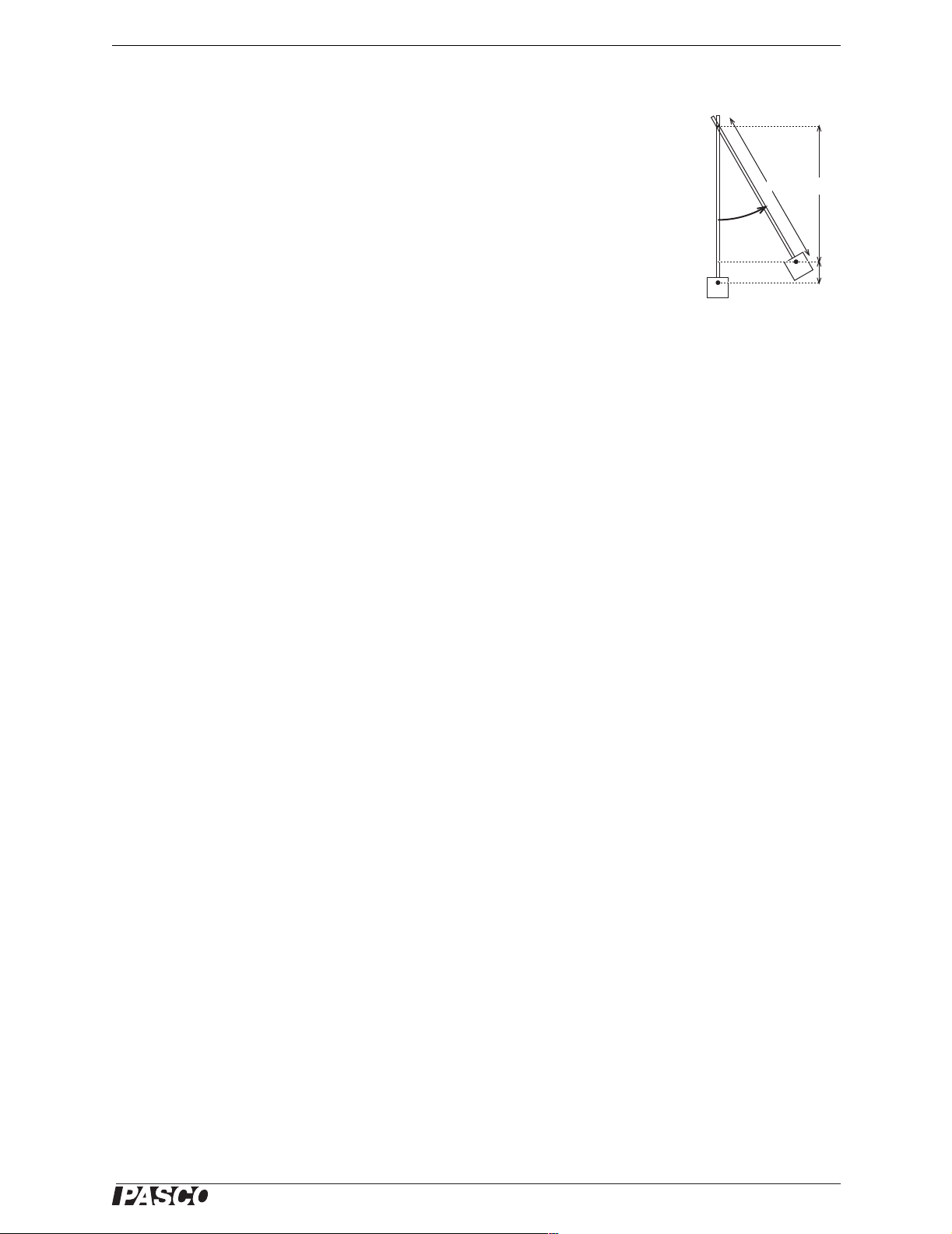
1. Use your value of θ
, the distance r, and Equation 2.5 to calculate the maxi-
max
mum height (h) that the center of mass rises as the pendulum swings up (see Figure 2.2).
(eq. 2.5) h = r (1 - cos (θ
max
))
h = _____________________
2. Use your value of h and Equation 2.4 to calculate the launch velocity of the ball.
V
= _____________________
0
Question
The theory for this experiment ignores the rotational inertia of the pendulum. Because
the pendulum is not really a simple pendulum (a point mass on a massless rod), a systematic error is introduced. Does this simplistic analysis tend to give a launch velocity
that is too high or too low? (See Experiment 3 for a more exact treatment.)
Further Study
Use two photogates to measure the launch velocity of the ball. Compare this value to
the value you found using the ballistic pendulum.
r
q
max
x = r cos (θ
r = x + h
Figure 2.2:
Calculating
max
h
x
h
)
®
11
Page 12

Mini Launcher Ballistic Pendulum Experiment 3: Conservation of Momentum and Energy
Experiment 3: Conservation of Momentum and Energy
Background
In this experiment you will analyze the angular collision between a ball and a physical
pendulum. You will compare the rotational momentum of the ball before the collision
to the rotational momentum of the pendulum-ball system after the collision. Both
rotational momenta are measured about the pendulum’s pivot point.
You will also compare the kinetic energy of the ball before the collision, the kinetic
energy of the pendulum-ball system just after the collision, and the maximum potential energy of the system after the collision.
The data-taking phase of this experiment has three parts. In Part 1 you will use photogates to measure the launch velocity of the ball. In Part 2 you will measure the maximum rotational velocity and angular displacement of the pendulum after the collision.
In Part 3 you will measure the rotational inertia of the pendulum-ball system.
Part 1: Measure Launch Velocity
Set up the launcher with two photogates and a photogate bracket (see Figure 3.1).
Measure the launch velocity (
als and use the average value.
If you will be doing the Advanced Study part of this experiment, also measure the
launch velocity for the medium and slow settings.
V
) of the ball on the fastest setting. Do several tri-
launch
Part 2: Record Ballistic Pendulum Data
Set-up
1. Set up the equipment and software as described on pages 4 through 6 with the
pendulum rod attached to the RMS at the center hole and the catcher side of the
pendulum facing the launcher. Do not attach the ballast mass to the bottom of the
catcher.
2. Slide the counterweight onto the pendulum rod above the RMS attachment point.
Adjust the position of the counterweight so the pendulum is perfectly balanced
without the ball. If you release the pendulum in the horizontal position, it should
not move. (See Figure 3.2.)
Counterweight
Figure 3.1: Launcher
with photogates
Figure 3.2: Pendulum balanced horizontally
3. Prepare a graphs to display angular velocity versus time and position versus time.
12
®
Page 13

Model No. ME-6829 Experiment 3: Conservation of Momentum and Energy
Procedure
1. Load the launcher and push the ball in to the third (fastest) position.
2. Move the pendulum into the vertical position. If it does not stay that way by
itself, hold it very lightly with one finger.
3. Start data collection.
4. Launch the ball so that it is caught by pendulum.
5. After the pendulum has swung out and back, stop data collection.
6. Note the maximum angular displacement measured by the RMS. Record it in
Table 3.1
7. Record the initial angular velocity (just after the collision) in Table 3.1. Because
this velocity occurs close to the collision, the RMS cannot measure it accurately.
Instead, note the maximum negative velocity that occurs when the pendulum
swings back toward the launcher (record it as a positive value). Though this
might be slightly smaller than the actual initial velocity (due to friction), it is a
more reliable measurement.
8. Repeat steps 1 through 7 several times.
9. Calculate the average maximum displacement (θ
velocity (ω
10. Measure the mass of the ball. m
).
0
Table 3.1: Angular Displacement and Velocity
Trial Maximum
Angle
Trial 1
Trial 2
Trial 3
Trial 4
Trial 5
Trial 6
Average:
θ
=
max
= _____________________
ball
) and the average initial
max
Initial Ang ular
Vel ocity
ω
=
0
11. Fire the ball into the catcher one more time (without recording data). Stop the
pendulum near the top of its swing so it does not swing back and hit the launcher
(this will prevent the ball from falling out or shifting).
12. Measure the distance, , from the center of rotation (where the pendulum attaches
to the RMS) to the center of ball. = _____________________
Part 3: Determine Rotational Inertia of Pendulum-ball System
Set-up
1. Remove the RMS from the mounting rod. (Leave the pendulum attached to the
RMS and leave the ball in the catcher.)
®
13
Page 14

Mini Launcher Ballistic Pendulum Experiment 3: Conservation of Momentum and Energy
2. Clamp the RMS on the mounting rod so that the pendulum can rotate in a hori-
zontal plane (see Figure 3.3).
Clamped-on
pulley
Hanging
mass
Figure 3.3: Setup for determining rotational inertia
3. Clamp a pulley to the RMS and set up a string and hanging mass (approximately
20 g to 30 g) as shown in Figure 3.3. Wind the string a few times around the middle step of the three-step pulley. Adjust the angle and height of the clamped-on
pulley so that the string will unwind and run over the pulley with as little friction
as possible.
Procedure
1. Start data collection.
2. Release the hanging mass.
3. After the string has unwound from the three-step pulley, stop data collection.
4. Determine the angular acceleration of the pendulum (α) from the slope of the
angular velocity versus time graph. α = _____________________
5. Measure the radius of the middle step of the three-step pulley.
R
= _____________________
pulley
6. Measure the mass of the hanging mass. m = _____________________
7. Calculate the acceleration (a ) of the hanging mass.
a = α R
pulley
8. Calculate the tension in the string (FT). Since the hanging mass is accelerating,
the string tension is not the weight of the mass. Writing Newton’s 2nd Equation
for the free-body diagram in Figure 3.4 yields:
F
T
a
mg
Figure 3.4: Free-body
diagram of hanging
mass
14
where g =9.8 m/s2.
F
= _____________________
T
ma = mg − F
T
®
Page 15
Model No. ME-6829 Experiment 3: Conservation of Momentum and Energy
9. Calculate the torque (τ) applied to the pulley by the string.
τ = R
pulleyFT
10. Calculate the rotation inertia (I) of the pendulum-ball sys-
tem using the rotational form of Newton’s 2nd Law:
τ = Iα
I = _____________________
Analysis
1. Calculate the initial angular momentum of the ball
(L
is calculated about the pendulum pivot.
2. Calculate the angular momentum of the ball-pendulum
system (L
) just before the collision. The angular momentum
launch
V
= m
L
launch
) immediately after the collision.
0
ball
launch
q < 90°
L
= Iω
0
0
3. Calculate the kinetic energy of the ball (K
launch
collision.
K
launch
1
---
=
2
m
ballV0
2
4. Calculate the kinetic energy of the ball-pendulum system
(K
) immediately after the collision.
0
1
2
---
K
=
Iω
0
0
2
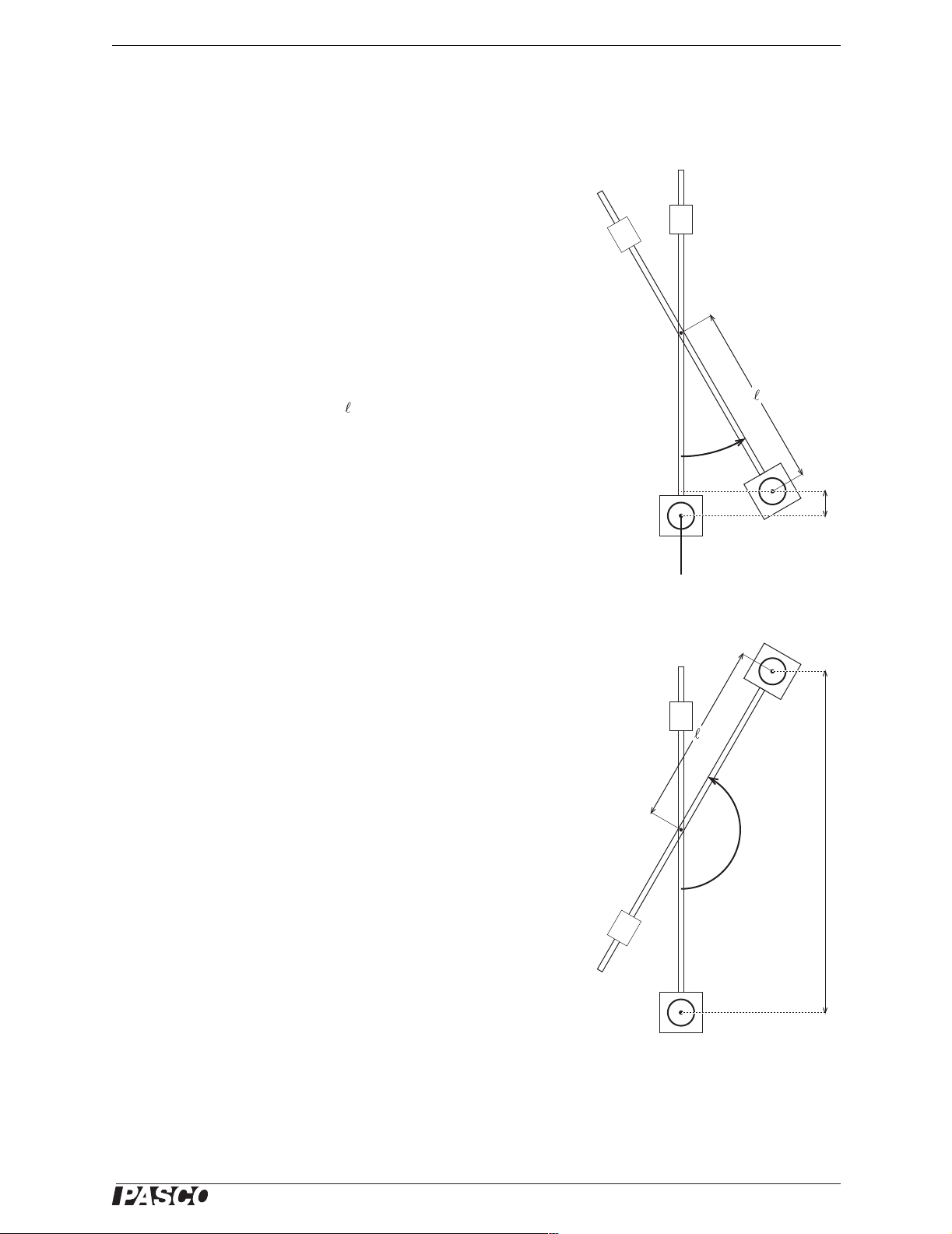
5. Use the maximum angular displacement of the pendulum
(θ
) to calculate the change in height (h
max
) of the ball.
max
Refer to Figure 3.5.
6. Calculate the gain in potential energy of the ball (∆U
∆U
= m
ball
g h
max
ball
Questions
) before the
).
ball
h
Center of ball
h
q < 90°
1. Why did you calculate the ball’s rotational momentum
rather than the linear momentum? Why did you calculate
the rotational momentum around the pendulum pivot rather
than the center of the ball?
2. Compare the rotational momentum of the ball before the
collision to the rotational momentum of the pendulum-ball
system just after the collision. Was momentum conserved?
®
Figure 3.5: Calculating h
15
Page 16

Mini Launcher Ballistic Pendulum Experiment 3: Conservation of Momentum and Energy
3. Compare the kinetic energy of the ball before the collision to the kinetic energy
of the pendulum-ball system just after the collision. Was energy conserved in the
collision?
4. What was the gain in potential energy of the pendulum (not including the ball)?
What was the purpose of the counterweight?
5. Compare the kinetic energy of the pendulum-ball system just after the collision to
the gain in potential energy of the ball. Was energy conserved as the pendulum
swung after the collision?
Further Study
I. Different Launch Speeds
Repeat the experiment for the slow and medium launch speeds. How does changing
the launch speed affect how well momentum is conserved?
Look at the ratio of initial kinetic energy (of just the ball) to the kinetic energy of the
pendulum-ball system (just after the collision). How does the launch speed of the ball
affect this ratio?
II. Different Center of Mass
Repeat the experiment without the counterweight. This time, you will need to find the
center of mass of the pendulum-ball system (see Experiment 2). Measure the distance
(r) from the axis of the RMS to the center of mass. When you calculate the potential
energy gain of the system, the height (h) is the change in height of the center of mass
of the system, not the ball.
III. Elastic Collision
Examine the difference between catching the ball (completely inelastic collision) and
allowing the ball to hit the bumper on the back of the catcher:
1. Place the counter-weight on the lower half of the pendulum rod between the mid-
dle hole and the catcher. Fasten the pendulum to the RMS using the middle hole
with the bumper side towards the launcher. There should be a gap of a few centimeters between the end of the launcher and the bumper.
2. Launch the ball at its slowest speed. What happens to the ball when it hits the
rubber bumper on the catcher? Adjust the position of the counter weight so that
the ball drops straight down after the collision. If the counterweight is positioned
too low, the ball bounces backwards. If the counterweight is too high, the ball
still has some forward velocity. You want the horizontal velocity of the ball to be
zero after the collision.
3. Perform the experiment as before and measure the maximum displacement
(θ
) and initial angular velocity (ω0) of the pendulum.
max
4. Measure the rotational inertia of the pendulum without the ball.
Find the pendulum’s center of mass (without the ball). Measure the distance r
from the axis of the RMS to the center of mass.
5. Perform the analysis for energy and momentum as before. What is the kinetic
energy of the ball immediately after the collision? Why?
16
®
Page 17

Model No. ME-6829 Experiment 3: Conservation of Momentum and Energy
When you calculate the gain in potential energy, remember that h is the change in
height of the center of mass of the pendulum, not including the ball.
Is this a perfectly elastic collision? What is the percentage of the kinetic energy
lost (converted to thermal energy) during the collision?
6. Turn the pendulum around and repeat the experiment for catching the ball. (Do
not change the position of the counterweight.) Note that both the rotational inertia and the center of mass (and thus the distance r) will change due to the ball
being in the catcher.
7. For the two cases (ball hitting the bumper and ball being caught), compare the
angular velocity of the pendulum just after the collision. Compare the maximum
angular displacement for the two cases. Which type of collision causes the
greater angular displacement? Why?
IV. Alternative Determination of Rotational Inertia
In the procedure above, you found the rotational inertia of the pendulum by applying
a known torque and measuring the resulting angular acceleration. An alternate
method is to measure the period of oscillation.
For a physical pendulum of rotational inertia I and mass M, the theoretical period (for
low-amplitude oscillations) is given by
T 2π
I
-----------=
Mgr
where r is the distance from the axis of rotation to the center of mass of the pendulum.
Measure the period of the pendulum (with a low amplitude) and calculate its rotational inertia. Compare this to the answer you got by applying a known torque.
®
17
Page 18

Mini Launcher Ballistic Pendulum Technical Support
Technical Support
For assistance with any PASCO product, contact PASCO at:
Address: PASCO scientific
10101 Foothills Blvd.
Roseville, CA 95747-7100
Phone: 916-786-3800 (worldwide)
800-772-8700 (U.S.)
Fax: (916) 786-3292
Web: www.pasco.com
Email: support@pasco.com
Limited Warranty
For a description of the product warranty, see the PASCO catalog.
Copyright
The PASCO scientific 012-09851A
mission is granted to non- profit educational institutions for reproduction of any par t of this manual, providing the reproductions are
used only in their laboratories and classrooms, and are not sold for profit. Reproduction under any other circumstances, without the
written consent of PASCO scientific, is prohibited.
Mini Launcher Ballistic Pendulum Instruction Manual
is copyrighted with all rights reserved. Per-
Trademarks
PASCO, PASCO scientific, DataStudio, PASPORT, Xplorer, and Xplorer GLX are trademarks or registered trademarks of PASCO scientific, in the United States and/or in other countries. All other brands, products, or service names are or may be trademarks or service marks of, and are used to identify, products or services of, their respective owners. For more information visit
www.pasco.com/legal.
Authors: Jon Hanks
Alec Ogston
18
®
 Loading...